

advertisement
Flyback Controller Simplifi es Design of Low Input Voltage DC/DC
Converters – Design Note 1016
David Burgoon
Introduction
Small, high effi ciency DC/DC converters are critical to
the design of leading-edge electronics. Achieving high
accuracy and effi ciency traditionally means adding extra
components, complex ity, and size. Not so with the LT3837.
This fl yback controller serves 10W to 60W isolated applications with high performance, simplicity, small size,
and a minimum component count.
High-Effi ciency Controller Capabilities
The LT®3837 operates from a 4.5V to 20V input, but the
converter input range can be extended upwards by using
regulator and/or a bias winding on the transformer.
a V
CC
It also provides a synchronous rectifi er output with
adjustable timing to optimize effi ciency and enhance
cross-regulation in multiple-output supplies.
The LT3837 eliminates the need for the traditional secondary-side reference, error amplifi er, and optoisolator
circuits by sampling the fl yb ack voltage on a primary-side
winding. Accuracy is enhanced with output resistance
compensation. Current mode control with leading edge
V
IN
9V TO 18V
22µF
25V
86.6k
1%
15k
1%
BAS16
2N3906
3.01k
1%
12k
FB
UVLO
PGDLY
tONSYNC
100k
V
CC
R
OCMP
1.37k
1%
22.1k
1µF
U1
LT3837EFE
ENDLY OSCAP
150k
1%
SG
SG
SGND/PGND
47pF
blanking yields a high performance loop that is easy to
compensate.
The operating frequency is adjustable from 50kHz to
250kHz or can be synchronized to an external clock.
Soft-start provides well controlled start-up with limited
inrush current. Protection features include current limit
w i t h s o f t - s t a r t c y c l i n g f o r s e v e r e o v e r l o a d s , u n d e r v o l t a g e
lockout, and thermal shutdown.
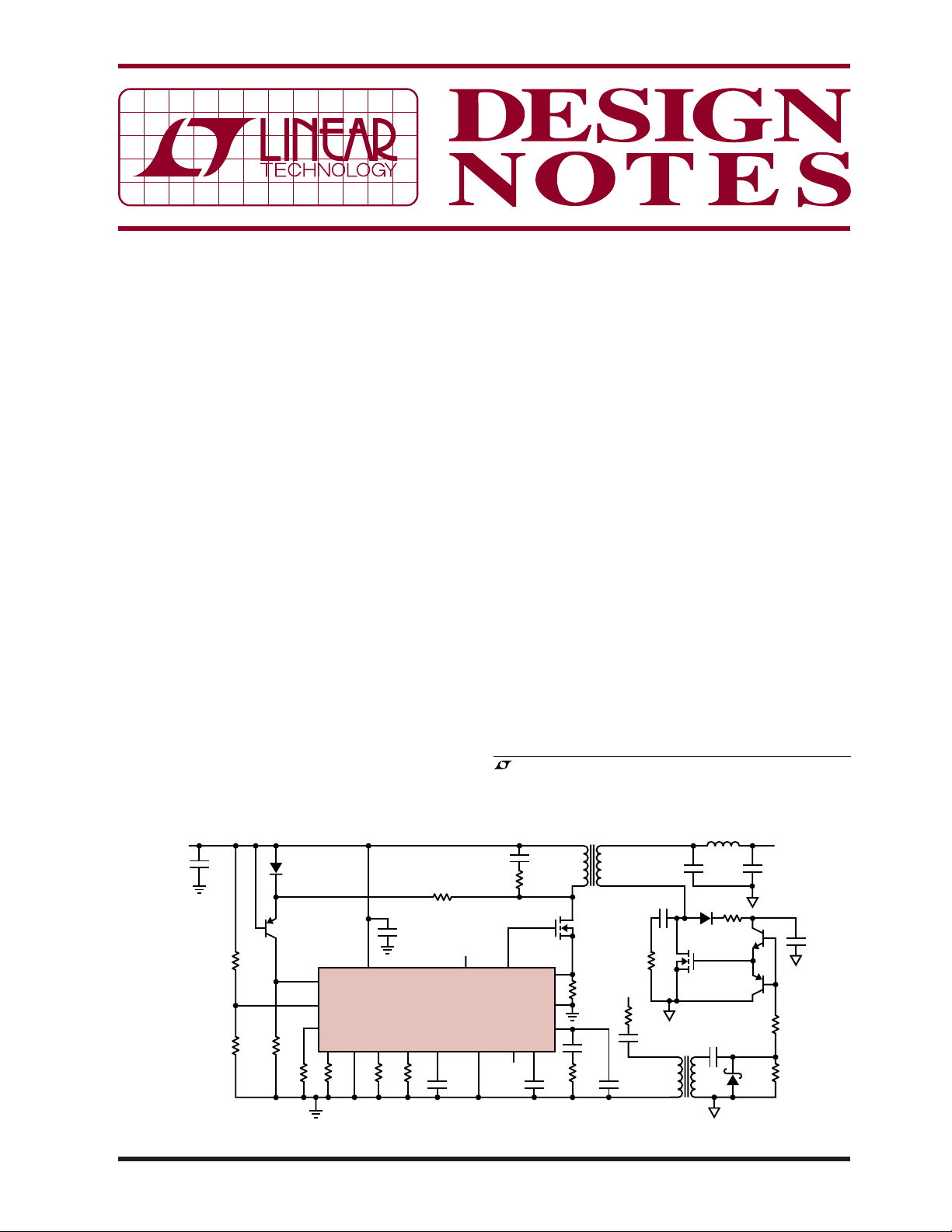
3.3V, 10A Converter Operates from a 9V to18V
Source
The circuit shown in Figure 1 is a fl yback design for a 3.3V,
10A output from a 9V to 18V input with a minimum of
extern al components. The LT3837 samples the volt age on
the primary winding during the fl yback interval to provide
superb regulation. Figure 2 shows ruler-fl at regulation at
9V input, and a tight regulation window of ±0.7% over
line and load. Synchronous rectifi cation with adjustable
, LTC and LT are registered trademarks of Linear Technology Corporation.
All other trademarks are the property of their respective owners.
IHLP2525CZERR10M
B0540W
Si7336ADP
•
•
0.1µH
47µF × 3
2.2nF
V
OUT
3.3V AT 10A
220µF
6TPE220MI
10
1µF
15
10k
BAT54
DN1016 F01
PG
SFST
2.2nF
10
SENSE
SENSE
C
CMP
V
+
–
C
0.1µF
T1
•
•
Si7852DP
0.008
0.5W
3.3nF
20k
1nF
1nF
4.7
SG
330
0.1µF
PA0184
Figure 1. Low Parts Count, 9V to 18V Input to 3.3V/10A Output Isolated Flyback Converter with ±0.7% Regulation
12/06/1016
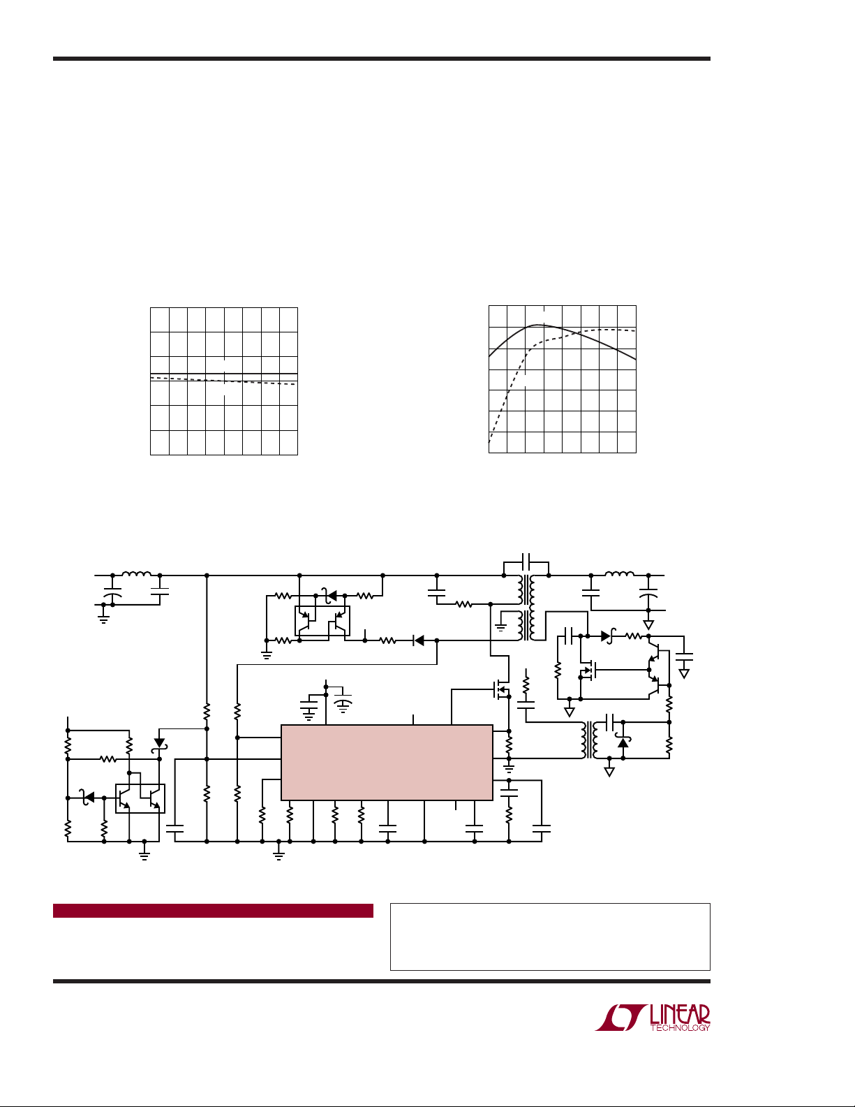
timing yields excellent ef fi ciency— 88% over a wide range
of operating conditions—as shown in Figure 3.
3.3V, 10A Converter Operates from a 9V to 36V Source
Figure 4 shows an enhanced circuit that extends the input
op erating r ange of the LT3837 to 9V to 36V. Oper a tion is
converted to hysteretic start-up for effi cient wide-range
operation. Q1 provides a low-drop current source for
start-up, and Q2 creates a suitable undervoltage circuit
for V
on the transformer, result in low V
. These circuits, together with the VCC winding
CC
power at higher
CC
input voltages and low dissipation cycling when operating into a short circuit. This circuit is implemented in a
3.6
3.5
3.4
3.3
OUTPUT (V)
3.2
3.1
3.0
2
35
9V
IN
18V
IN
46
LOAD CURRENT (A)
7
8
10
9
DN1016 FO2
2
footprint. This circuit exhibits excellent regulation
1.5in
of ±1.2% over line and load, and effi ciency of 88% over
much of its operating range.
Conclusion
The LT3837 is part of a new class of fl yback controllers
developed by Linear Technology to satisfy the demand
for economical, high performance power converters. It
provides synchronous rectifi er drive and eliminates the
need for secondary regulation circuits and optoisolators.
The LT3837 makes it easy to implement high performance Flyback designs that are cost effective, small
and effi cient.
90
88
86
84
82
EFFICIENCY (%)
80
78
76
2
9V
IN
18V
IN
46 10
57
39
LOAD CURRENT (A)
8
DN1016 F03
Figure 2. Regulation of the Converter in Figure 1 Figure 3. Effi ciency of the Converter in Figure 1
4.7nF
250V
9V TO 36V
–V
9V TO 36V
V
CC
4.64k
MBT3904DW1
BZT52C6V2S
21.5k
1µH
+
100µF
50V
47k220k
100k
3.3µF × 3
50V
BAT54WS
Q2
100k
24.9k
3.01k17.4k
12.1k 1.07k 147k
BAT43WS
100k 316
Q1
MBT3906DW1T1
V
V
CC
+
33µF
V
CC
R
OCMP
16V
ENDLY OSCAP
0.1µF
FB
UVLO
PGDLY
tONSYNC
100k
CC
LT3837EFE
121100k
U1
470pF
BAS21
SG
SG
SGND/PGND
47pF470pF
33
HAT2173H
PG
SFST
SENSE
SENSE
C
CMP
PA1835NL
+
–
V
C
0.1µF
•
•
7m
2.15k
SG
1.5nF
DN1016 F04
EFD20
L
P
(N = 6 : 2)
•
120
0.1µF
= 5µH
1nF
4.7
PA0184
220pF
V
IN
IN
CMPSH1-4
•
0.1µH
47µF × 3
6.3V
FMMT618
Si7336ADP
FMMT718
4.7nF
•
Figure 4. Wide Range, 9V to 36V to 3.3V/10A Isolated Flyback Converter with ±1.2% Regulation
Data Sheet Download
www.linear.com
For applications help,
call (408) 432-1900, Ext. 2134
+
10
BAT54WS
V
OUT
3.3V AT 10A
220µF
6.3V
–V
OUT
3.3V AT 10A
15
10k
1µF
Linear Technology Corporation
1630 McCarthy Blvd., Milpitas, CA 95035-7417
(408) 432-1900
●
FAX: (408) 434-0507 ● www.linear.com
dn1016f LT 1206 • PRINTED IN THE USA
© LINEAR TECHNOLOGY CORPORATION 2006
 Loading...