

L DESIGN FEATURES
CTRL_SEL
PWM
SW
INDUCTOR
CURRENT
PWMGH
PWMGL
LED CURRENT
I
CTRL_L
I
CTRL_L
I
CTRL_H
I
CTRL_H
LT3743
V
IN
V
IN
I
REG
V
OUT
FOR I
REG
DETERMINED
BY CTRL_H
V
OUT
FOR I
REG
DETERMINED
BY CTRL_L
HG
CBOOT
PWM
CTRL_SEL
CTRL_L
CTRL_H
LED LOAD
SW
V
CC_INT
LG
GND
SENSE
+
SENSE
_
PWMGH
PWMGL
L R
S
+ +
High Current/High Speed LED Driver
Revolutionizes PWM Dimming
Introduction
Power drivers that can produce regulated high current pulses are used
in a number of lighting applications,
ranging from high current LEDs in
DLP projectors to high power laser
diodes. For instance, in high end
video projectors, high power LEDs are
used to produce color illumination.
The RGB LEDs in these projectors
require precise dimming control for
accurate color mixing—in this case,
more control than simple PWM dimming can offer. Typically, to achieve
the wide dynamic range required in
color mixing, LED drivers must be
able to rapidly switch between the
two disparate regulated peak current
states, and overlay PWM dimming
without disruption. The LT3743 has
the ability to meet these demanding
accuracy and speed requirements.
The LT3743 is a synchronous
buck DC/DC controller that utilizes
fixed-frequency, average current mode
control to accurately regulate the
inductor current through a sense
resistor in series with the inductor.
The LT3743 regulates the current in
any load with an output voltage range
from 0V to 2V below the input rail with
±6% accuracy.
Precision, broad-range LED current
control is achieved by combining accurate analog dimming (high and low
states) with PWM dimming. Analog
dimming is controlled via the CTRL_L,
CTRL_H, and CTRL_T pins; PWM
dimming via the PWM and CTRL_SEL
pins. A rapid transition between the
high and low analog states is made
possible with the LT3743’s unique use
of externally switched load capacitors,
which allows the LT3743 to change
regulated LED current levels within
several microseconds. The switching
frequency may be programmed from
200kHz to 1MHz using an external resistor and synchronized to an external
clock from 300kHz to 1MHz.
16
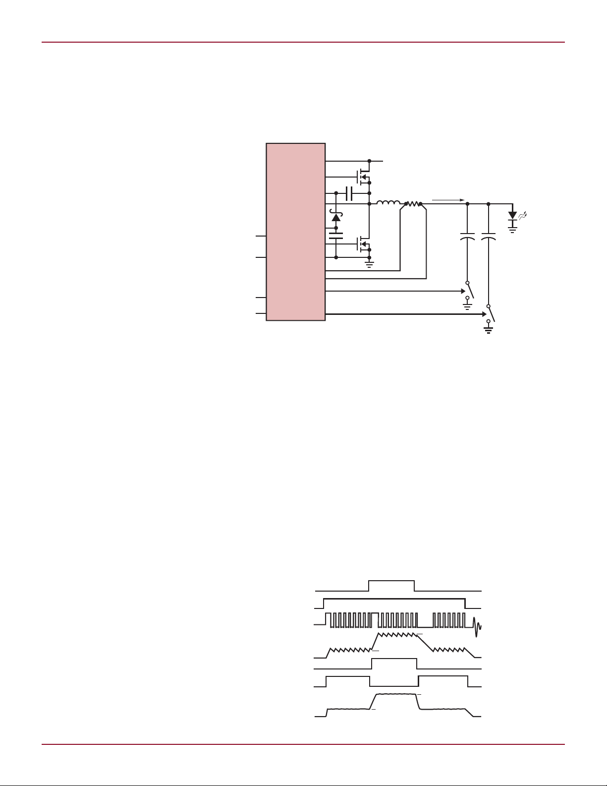
Figure 1. Basic switched-capacitor topology
Switched Output
Capacitor Topology
In traditional current regulators, the
voltage across the load is stored in the
output capacitor. If the load current
is suddenly changed, the voltage in
the output capacitor must charge or
discharge to match the new regulated
current. During the transition, current in the load is poorly controlled,
resulting in slow load current response
time.
The LT3743 solves this problem
with a unique switched output capacitor topology, which enables ultrafast
load current rise and fall times. The
basic idea behind the topology is that
Figure 2. LED current PWM and CTRL_SEL dimming
by Josh Caldwell
the LT3743 acts as a regulated current source driving into the load. The
voltage drop across the load for a given
current is stored in the first switched
output capacitor. When a different
regulated current state is desired, the
first output capacitor is switched off
and a second capacitor is switched in.
This allows each capacitor to store the
voltage drop for the load corresponding
to the desired regulated current.
Figure 1 shows the basic topology
with the various control pins. The PWM
and CTRL_SEL pins are digital control
pins that determine the state of the
regulated current. The CTRL_H and
CTRL_L pins are analog inputs with a
Linear Technology Magazine • December 2009
DESIGN FEATURES L
PWM DIMMING DUTY CYCLE (%)
0 20 40 60 80 100
EFFICIENCY (%)
0
10
20
30
40
50
60
70
80
90
100
EN/UVLO
PWM
CTRL_SEL
EN/UVLO
PWM
CTRL_SEL
HG
V
IN
CBOOT
V
REF
CTRL_L
CTRL_H
CTRL_T
LT3743
RT
SYNC
SW
LG
GND
VCH
VCL
SENSE
+
SENSE
–
PWMGH
PWMGL
V
CC_INT
100nF
L1
1.0µH
22µF
C1
330µF
×3
2.5mΩ
FB
10nF
34k
4.7nF
34k
D1: LUMINUS PT120
D2: PMEG4002EB
L1: IHLP4040DZER1R0M01
M1: RJK0365DPA
M2: RJK0346DPA
M3, M4: Si7236DP
C1, C2, C3: PTPR330M9L (THREE IN PARALLEL)
D2
4.7nF
82.5k
100k
100k
C3
330µF
×3
D1
40.2k
10k
1µF
2nF
R
NTC
10k
220µF
M1
M2
M3
M4
V
IN
12V
V
OUT
20A MAXIMUM
1µF
C2
330µF
×3
SS
R
HOT
499Ω
10Ω 10Ω
33nF
CTRL_SEL
5V/DIV
PWM
5V/DIV
SW
20V/DIV
I
LED
10A/DIV
20µs/DIVV
IN
= 24V
0A TO 2A TO 20A LED CURRENT STEP
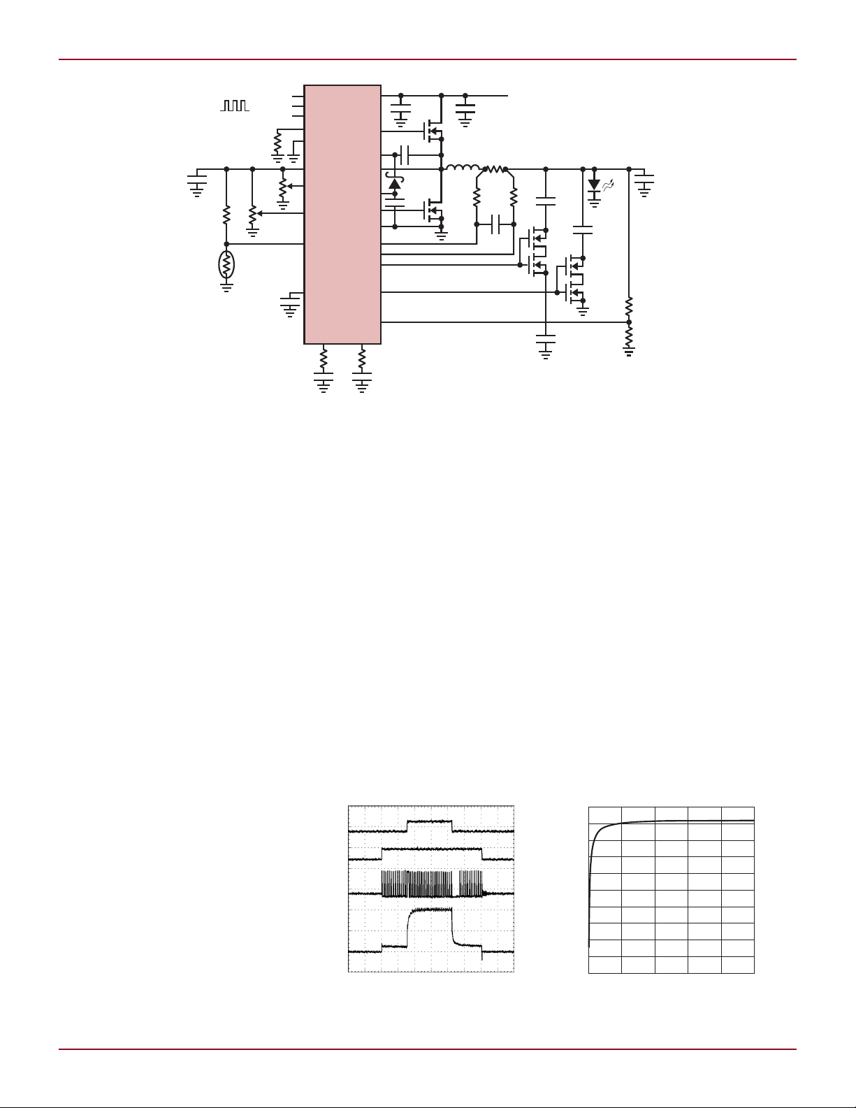
Figure 3. A 24V, 20A LED driver using switched output capacitors
full-scale range of 0 to 1.5V, producing
a regulated voltage of 0mV to 50mV
across the current sense resistor.
Figure 2 shows the timing waveforms in response to the various states
of the PWM and CTRL_SEL pins. When
PWM is low, all switching is terminated
and both output capacitors are disconnected from the load.
Although the LT3743 may be
configured with switched output
capacitors, it is easily adapted to any
traditional analog and/or PWM dimming scheme.
Switching Cycle
Synchronization
The LT3743 synchronizes all switching edges to the PWM and CTRL_SEL
rising edges. Synchronization gives
system designers the freedom to use
any periodic or non-periodic PWMdimming pulse width and duty cycle.
This is an essential feature for high
current LED drivers during recovery
from a zero or low current state to a
high current state. By restarting the
clock whenever the CTRL_SEL or PWM
signals go high, the inductor current
begins ramping up immediately without having to wait for a rising edge of
the clock. Without synchronization,
the phase relationship of the clock
edge and the PWM edge would be
uncontrolled, possibly resulting in
Linear Technology Magazine • December 2009
visible jitter in the LED light output.
When using an external clock with
the SYNC pin, the switching cycle
resynchronizes to the external clock
within eight switching cycles.
A 24V, 20A LED Driver Using
Switched Output Capacitors
for High End DLP Projectors
High end DLP projectors demand
the highest quality image and color
reproduction. To achieve high color
accuracy, variations in the color of
individual LEDs are corrected by mixing in the other two color LEDs. For
example, when the red LED is on at full
current, the blue and green LEDs are
turned on at low current levels so they
can be mixed in to produce accurate
red. This technique requires the ability
Figure 4. Zero to 2A to 20A LED current steps
to rapidly transition between relatively
low (~2A) and high (~20A) LED currents so that PWM dimming edges are
preserved. Figure 3 shows a 24V/20A
LED driver for use specifically with
high end DLP projectors.
The relatively low switching frequency of 450kHz allows for a very
small 1.0µH inductor. With 25% ripple
current, the transition times between
the high and low current states is
about two microseconds. The large
1mF output capacitors store the voltage drop across the LED for the two
different current states and provide
instantaneous current when the
MOSFET dimming switches are turned
on. Use of several low ESR capacitors
in parallel is critical to providing rapid
LED current transitions.
Figure 5. 12V, 20A PWM dimming efficiency
using a green LED
17

L DESIGN FEATURES
EN/UVLO
PWM
CTRL_SEL
EN/UVLO
INTV
CC
CTRL_SEL
HG
V
IN
CBOOT
V
REF
CTRL_H
CTRL_L
CTRL_T
LT3743
RT
SYNC
SW
LG
GND
VCH
VCL
SENSE
+
SENSE
–
PWMGH
PWMGL
V
CC_INT
100nF
L1
10µH
22µF
25mΩ
FB
10nF
34k
4.7nF
34k
4.7nF
82.5k
40.2k
D1
10k
2.2nF
8.2µF
M1
M2
M3
V
IN
6V TO 36V
V
OUT
2A MAXIMUM
2.2µF
1µF
SS
CONTROL
INPUT
D1: LUMINUS CBT-40
D2: PMEG4002EB
L1: IHLP4040DZE10R0M01
M1, M2: Si7848BDP
M3: Si2312BDS
D2
SW
10V/DIV
I
L
2A/DIV
CTRL_SEL
5V/DIV
I
LED
1A/DIV
20µs/DIV
EN/UVLO
PWM
CTRL_SEL
EN/UVLO
PWM
V
CC_INT
HG
V
IN
CBOOT
V
REF
CTRL_L
CTRL_H
CTRL_T
LT3743
RT
SYNC
SW
LG
GND
VCH
VCL
SENSE
+
SENSE
–
PWMGL
PWMGH
V
CC_INT
150nF
L1
1.65µH
22µF
2.5mΩ
FB
10nF
51k
4.7nF
82.5k
10Ω 10Ω
60.4k
10k
2.2nF
R
NTC
10k
82µF
M1
D2
M2
M3
D1: LUMINUS PT121
D2: PMEG4002EB
L1: MVR1271C-162ML
M1: RJK0365DPA
M2: RJK0328DPB
M3: SiR496DP
C1: PTPR330M9L (THREE IN PARALLEL)
V
IN
6V TO 30V
V
OUT
20A MAXIMUM
C1
330µF
×3
D1
1µF
SS
R
HOT
499Ω
CONTROL
INPUT
33nF
Figure 6. A 6V to 36V input, 2A LED driver with current limited shunted output
The regulated high and low currents
are set by voltage dividers from the
V
pin to the CTRL_L and CTRL_H
REF
pins. The ±2%, 2V reference at V
is also used to provide the reference
signal the temperature derating circuit
applied at CTRL_T (see “Thermally
Derating the LED Current” below).
To reduce potentially large start-up
currents, the LT3743 uses a unique
soft-start circuit that throttles back the
regulated currents, providing full drive
when the soft-start pin is charged to
Figure 8. A 6V to 30V input, 20A LED driver with switched cathode PWM dimming
18
1.5V. To minimize the transition time
between current levels, the LT3743
employs individual compensation for
each level so that the current control
REF
loop may return to steady-state operation as quickly as possible. Figure 4
shows the LED current step from 0A
to 2A to 20A.
High Efficiency Over a Wide
Range of PWM Duty Cycles
Power dissipation is a critical design
parameter in portable DLP projectors.
Figure 7. 0A to 2A current limited shunted
output PWM dimming
Unlike many shunt-type high current
LED drivers currently available, the
LT3743 has excellent efficiency over
a wide range of PWM duty cycles. By
delivering power only to the load instead of either shunting power away or
charging the output capacitor, most of
the energy lost in common traditional
PWM-dimmed drivers is conserved.
Figure 5 shows the efficiency with VIN
= 12V, driving a green LED between
0A and 20A over the entire duty cycle
range.
Linear Technology Magazine • December 2009

DESIGN FEATURES L
PWM
5V/DIV
I
LED
10A/DIV
SW
10V/DIV
10µs/DIV
Shutdown and
Precision Enable
When delivering high load currents,
the amount of supply undervoltage
lock-out (UVLO) hysteresis required
for proper operation is highly dependent on board layout. For maximum
flexibility, the LT3743 incorporates
a precision enable threshold with a
5.5µA current source flowing into the
pin when the EN/UVLO pin is lower
than 1.55V. Using a voltage divider
from the input supply to ground any
amount of hysteresis may be added
to the system. To conserve power in
portable applications, the LT3743
is completely disabled and supply
current drops below 1µA when the
EN/UVLO pin is lower than 0.5V.
Thermally Derating
the LED Current
Proper thermal management is vital
with any high current load to protect
expensive high current LEDs and
prevent system-wide damage. The
LT3743 uses the CTRL_T pin to reduce
the effective regulated current in the
load for both the high and low control
currents. Whenever CTRL_T is lower
than the control voltage on the CTRL_L
or CTRL_H pins, the regulated current
is reduced. The temperature derating
is programmed using a temperature
dependent resistor divider from the
V
pin to ground.
REF
Output Voltage Protection
Voltage protection is important to
prevent damaging expensive projector
LEDs. The LT3743 utilizes the FB pin
to provide a regulated voltage point for
the output. To simplify system design,
the LT3743 uses an internal 1V reference, softly reducing the regulated
current when the FB voltage reaches
900mV.
Powerful Gate Drivers
To provide adequate drive and reduce
switching losses in high current
power MOSFETs, the LT3743 uses very
strong switching MOSFET drivers. The
on-resistance of the LG and HG PMOS
pull-up drivers is typically 2.5Ω. The
LG and HG NMOS pull-down drivers
on-resistance is typically less than
1.3Ω. With on-resistance this low, two
high current MOSFETs may be used
in parallel for applications exceeding
20A. Most currently available LED
drivers do not provide adequate gate
drive for dimming MOSFETs and as a
result need an additional external gate
driver. The LT3743 integrates this into
the PWMGL and PWMGH drivers and
has a 2Ω typical NMOS pull-down and
a 3.7Ω typical PMOS pull-up to drive
any 5V dimming MOSFET.
Traditional PWM Dimming
The LT3743 adapts to any traditional
PWM dimming method. Shunted output dimming used by competing LED
drivers wastes energy and has poor
efficiency for LED duty cycles below
The LT3743 produces
ultrafast high current
LED rise times while
providing accurate current
regulation. Its ability to
support multiple current
states meets the demands of
high performance theater-
quality DLP projectors by
allowing LED colors to be
easily mixed. In addition to
speed, the LT3743’s switched
capacitor topology reduces
board size by allowing the
use of a compact, low value
inductor. Additional features
include switching cycle
synchronization, overvoltage
protection, high efficiency
and easy adaptability for
varied application needs.
approximately 50%. Since the LT3743
has two levels of current regulation,
the regulated current can to drop to
zero when the shunt is engaged. This
provides excellent efficiency even for
low LED duty cycles.
Figure 6 shows a 2A LED driver configured with a current-limited shunted
output. Note that the CTRL_L pin is
tied to ground, PWMGL is used to drive
Figure 9. 0A to 20A switched cathode PWM
dimming
the shunting MOSFET, and CTRL_SEL
is used for dimming. With CTRL_L tied
to ground, when the CTRL_SEL pin
is low, the shunt is engaged and the
current in the inductor is regulated
at 0A. When CTRL_SEL is high, the
shunting MOSFET is turned off, and
the regulated current is determined by
the voltage at the CTRL_H pin. Figure
7 shows the current-limited shunted
PWM dimming with a 12V input.
In addition to the shunt, the LT3743
is readily configured to driving the
dimming MOSFET in series with the
cathode of the LED. When multiple
current states are not required, this is
the preferred method of PWM dimming.
Figure 8 illustrates a 6V to 30V, 20A
LED driver with switched cathode PWM
dimming. Figure 9 shows switched
cathode, PWM dimming with a 0A to
20A current step and a dimming ratio
of 100:1.
Conclusion
The LT3743 produces ultrafast high
current LED rise times while providing accurate current regulation. Its
ability to support multiple current
states meets the demands of high
performance theater-quality DLP
projectors by allowing LED colors to
be easily mixed. In addition to speed,
the LT3743’s switched capacitor topology reduces board size by allowing the
use of a compact, low value inductor.
Additional features include switching
cycle synchronization, overvoltage
protection, high efficiency and easy
adaptability for varied application
needs.
L
Linear Technology Magazine • December 2009
19
 Loading...