

Step-Down Synchronous Controller Operates from Inputs Down
to 2.2V
Design Note 443
Wei Gu
Introduction
Many telecommunications and computing applications
need high effi ciency step-down DC/DC converters that
can operate from a very low input voltage. The high
output power synchronous controller LT3740 is ideal
for these applications, converting input supplies ranging
from 2.2V to 22V to outputs as low as 0.8V with load
c ur r e nt s fr o m 2 A to 2 0A . A pp l ic a t io n s i n c l ud e d i st r ib u te d
power systems, point-of-load regulation and conversion
of logic supplies.
A major challenge in designing a step-down converter
with low V
is that the gate voltage for the N-channel
IN
MOSFETs is not readily available. The LT3740 solves
this problem by integrating a DC/DC step-up converter
for generating its own MOSFET gate drive voltage with
a small inexpensive external inductor. This function
permits the use of inexpensive off-the-shelf 5V gatedrive MOSFETs, offering up to 3% higher ef fi ciency than
sub-logic gate-drive MOSFETs and eliminating the need
for a secondary supply.
The LT3740 operates at a fi xed 300kHz frequency and
employs valley current mode control to deliver excellent
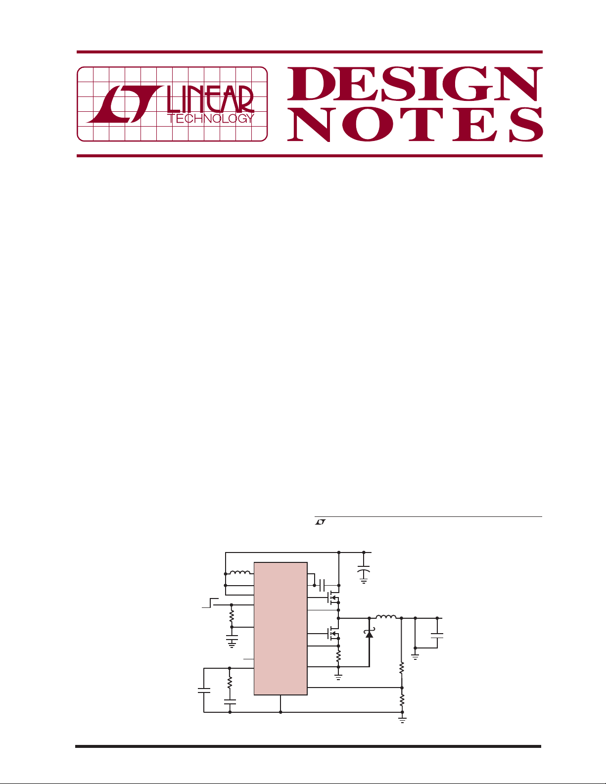
L2
100pF
22μH
100k
12k
1
μF
2200pF
SWB
V
IN
RANGE
SHDN
XREF
PGOOD
V
C
LT3740
GND
BGDP
BIAS
TGATE
SW
BGATE
SN
SN
FB
transient response and very low on-times. Furthermore,
a power good signal is available to monitor the output
voltage. The tracking capability built into XFER can be
used to implement control of the output voltage when
ramping up and ramping down. If less than 0.8V is applied
to XFER, the LT3740 uses this voltage as its reference
for regulation.
“Dying Gasp” Applications
The LT3740’s low VIN feature makes it a good fi t in “dying gasp” applications for high reliability computers. In
these systems, when the power gets cut, a large bank of
electrolytic capacitors at the input charged to 12V or so,
serve as input to the power controller. The LT3740 can
operate down to 2.2V, which allows it to run longer from
the input capacitors’ charged voltage than a controller
requiring a higher input voltage. This effectively reduces
the input capacitance requirements, which can save
signifi cant board space.
Figure 1 shows a typical application circuit. The LT3740
circuit, after its input power gets cut, is able to supply the
, LT, LTC and LTM are registered trademarks of Linear Technology Corporation.
All other trademarks are the property of their respective owners.
V
IN
12V
C
C
B
1μF
M1
PH8230E
M2
+
–
PH3830L
R
7mΩ
IN
3300μF
L1 0.9μH
D1
B320A
S
69.8k
78.7k
V
OUT
1.5V
10A
100μF
×3
06/08/443
DN443 F01
Figure 1. “Dying Gasp” Application Circuit
load for 40ms as shown in Figure 2. In comparison, the
output volt age would drop out after 25ms with a co ntroller
that shuts down when the input reaches 7V.
Generate a Negative Voltage from a Low Positive
V
IN
Figure 3 shows a 2.4V to 14V input to –3.3V at 3A output
converter. The LT3740 works particularly well in this application due to its wide input voltage range and ability
to operate down to 2.2V. The LT3740 also operates with
synchronous rectifi cation, which allows the use of high
effi ciency MOSFETs, instead of less effi cient switching
diodes.
Wide Input Voltage Range
The LT3740 offers high effi ciency over a wide input voltage range (2.2V to 22V) and produces output voltages
V
IN
10V/DIV
V
OUT
1V/DIV
VIN: 12V
: 1.5V
V
OUT
: 4A
I
OUT
10ms/DIV
Figure 2. Input and Output Voltages Waveforms When Input
Power is Removed
DN443 F02
as low as 0.8V. The LT3740 employs valley current mode
control to deliver excellent transient response and very
low on-times. Figure 4 illustrates low duty cycle waveforms for a 22V input, 0.8V output application at a fi xed
frequency of 300kHz.
Conclusion
The LT3740 can operate from low input voltages, providing a space- and cost-saving solution over a wide
input voltage range. The LT3740 is a versatile platform
on which to build DC/DC converter solutions that use
few external components and maintain high effi ciencies
over wide load ranges. The integrated step-up regulator
facilitates true single-supply operation with an input
voltage as low as 2.2V.
V
SW
5V/DIV
= 3A
I
OUT
1μs/DIV
Figure 4. LT3740 Low Duty Cycle Waveforms
DN443 F04
L2
22μH
100k
1
μF
12k
100pF
2200pF
Figure 3. A Positive to Negative Converter
Data Sheet Download
www.linear.com
SWB
V
IN
RANGE
SHDN
XREF
PGOOD
V
C
LT3740
GND
BGDP
BIAS
TGATE
SW
BGATE
SN
SN
PGND
V
IN
2.4V - 14V
C
C
B
1μF
M1
PH8230E
M2
+
–
FB
PH3830L
R
S
7m
IN
100μF
V
OUT
L1 0.9μH
D1
B320A
Ω
267k
80.6k
100μF
×3
V
OUT
–3.3V
3A
DN443 F03
For applications help,
call (408) 432-1900, Ext. 3565
Linear Technology Corporation
1630 McCarthy Blvd., Milpitas, CA 95035-7417
(408) 432-1900
●
FAX: (408) 434-0507 ● www.linear.com
dn443 LT/TP 0608 392K • PRINTED IN THE USA
© LINEAR TECHNOLOGY CORPORATION 2008
 Loading...