

L DESIGN FEATURES
V
BUS
OV
SENS
D0–D2
CHRG
NTC
USB
WALL
ADAPTER
HIGH VOLTAGE INPUT
7.5V TO 30V
TRANSIENT
TO 60V
SYSTEM
LOAD
M1
(OPTIONAL)
L1 = TDK, VLCF5020T-4R7NIR7-1
L2 = COILCRAFT, LPS4018-332MLC
M1 = VISHAY, Si 2333DS
D1 = DIODES INC., DFLS240
SEE THE LTC4098 DATASHEET FOR MORE INFORMATION
ON CONFIGURING THE NTC BATTERY TEMPERATURE
QUALIFICATION OR REDUCED IDEAL DIODE IMPEDANCE.
SINGLE-CELL
Li-Ion
C5
0.1µF
L2
3.3µH
L1
4.7µH
LTC4098
GND
SW
V
OUT
BATSENS
PROGCLPROG
WALLV
C
LT3653
HVOKGNDV
C
I
LIM
R3
1k
R2
3.01k
R4
6.04k
R1
27.4k
C4
10µF
6.3V
D1
TO µC
TO µC
C1
4.7µF
50V
C2
22µF
6.3V
C3
0.1µF
10V
V
IN
V
OUT
I
SENSE
SW
BOOST
OV
GATE
BAT
IDGATE
1.2A Monolithic Buck Regulator
Shrinks Supply Size and Cost with
Programmable Output Current Limit
Introduction
Power supplies are often overqualified
for their job. This is because power
ICs often specify a current limit that
is more than twice the rated output
current of the device. The power supply
components are sized to handle the
maximum current that the IC can deliver, even if loads are unlikely to draw
that current during normal operation.
The components are bigger and more
expensive than they need to be.
set an accurate maximum output cur-
rent on the supply once the real world
load is known. Accurately setting the
maximum output current reduces the
required current rating of the regulator’s power path components, thus
replacing big, expensive components
with smaller, less expensive ones.
A limit on the regulator’s maximum
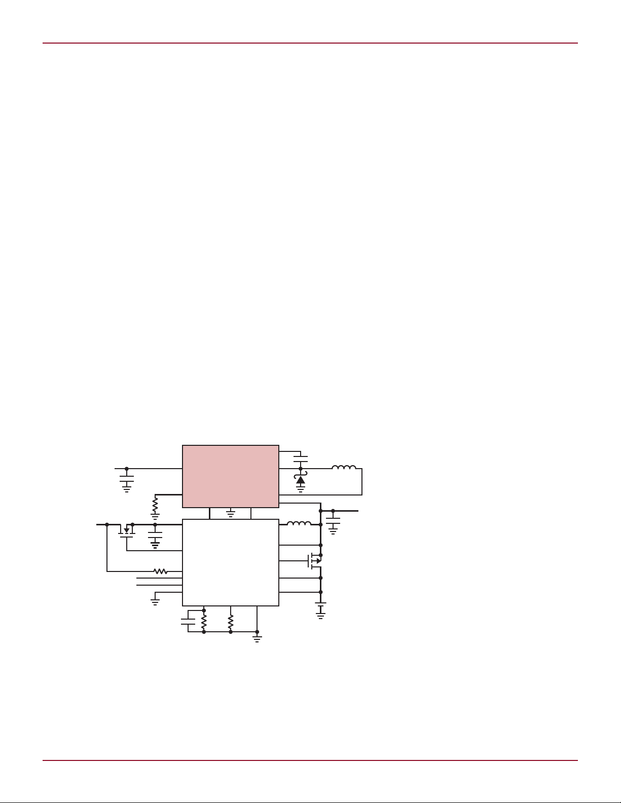
Figure 1. Charging a single cell Li-ion battery from either a USB input or high voltage input. This
solution offers a seamless, highly efficient, low part count approach to dual input charging and
PowerPath™ control of a Li-ion battery-powered application. If additional integration is required
for more system supplies, the LT3653 can be used in a similar fashion with the LTC3576 PMIC.
20
There is, however, an alternative:
output limits the maximum power
dissipation of both the supply and
the load, thus reducing the potential
for localized heating. Monitoring and
controlling the output current also
makes for a robust solution, which is
able to withstand harsh overload and
short circuit conditions.
The LT3653 and LT3663 are monolithic step-down switching regulators
that have an accurate output current
limit programmable from 400mA to
1.2A. The LT3663 is a general purpose high voltage step-down regulator
while the LT3653 is designed for use
with Linear Technology Bat-Track™
enabled battery chargers and power
management ICs (PMICs). The maximum input voltages of 30V (LT3653)
or 36V (LT3663) with 60V transient
ride through capability are well suited
by Tom Sheehan
to automotive, industrial, distributed
supply, and wall transformer applications.
Programmable
Output Current Limit
Monolithic switching regulators typically limit the peak switch current to
protect the internal switch from being
damaged during an overload or short
circuit event. The maximum switch
peak current limit is typically more
than two times the maximum output
current rating of the part. While the
peak switch current limit prevents
overstressing the IC, it does not keep
the entire application from overheating during an overload condition. For
example, a regulator with an output
current rating of 1A is typically capable
of providing over 2A at the output.
During an output overload condition,
the power dissipation of the regulator could more than double, making
thermal management more difficult.
The LT3653 and LT3663 reduce localized hot spots by controlling the total
power dissipation of the application
with a programmable, accurate current limit.
Conservative design principles call
for power path components that are
rated for worst-case currents. In the
above example, where a 1A part is
capable of delivering 2A, the power
path components must be sized for
greater than 2A, because during an
output short circuit or overload the
inductor and diode can conduct up
to 2A. In contrast, the PowerPath
components in LT3653 and LT3663
applications are sized based on the
programmed maximum output current limit. Therefore, an application
with a 750mA output current limit
requires only 750mA rated components. This allows for smaller, lower
Linear Technology Magazine • March 2009
DESIGN FEATURES L
LT3663
V
IN
V
IN
RUN
I
LIM
BOOST
SW
GND
0.1µF
2.2µF
22µF59k28.7k
11k
6.8µH
DIODES,
INC.
DFLS240
I
SENSE
V
OUT
V
OUT
FB
ON OFF
OUTPUT CURRENT (A)
OUTPUT VOLTAGE (V)
6
5
4
0
1
2
3
0 0.2 0.4 0.6 0.8 1 1.41.2
R
ILIM
= 28.7k
cost devices and a smaller overall
application footprint.
In early product development,
system designers usually don’t know
how much current their load will draw.
Once they choose a power supply, they
are committed. However, with the programmable current limit of the LT3653
and LT3663, once the load has been
fully characterized, they can change
the output current limit by changing
an inexpensive 1% resistor.
The output current limit is implemented by monitoring and controlling
the average inductor current. When an
overcurrent event occurs, the regulator
disables the power switch. This robust
solution withstands short circuit and
overload conditions throughout the
entire input voltage range.
The LT3653 Plays Well with
Bat-Track Battery Chargers
The LT3653 is a 1.5MHz constant
frequency, current mode control,
step-down regulator designed for use
with Linear Technology’s Bat-Track-
enabled battery charger PowerPath
power managers. The LT3653 steps
down a high voltage input to power the
system load and charge a single-cell
Li-ion battery charger.
Minimizing the voltage across
a linear battery charger increases
efficiency. To accomplish this, a BatTrack battery charger controls the
LT3653’s VC Pin, overriding the error
amplifier. In this way, the output voltage of the LT3653 is regulated by the
battery charger to a potential slightly
above the battery voltage, typically
300mV.
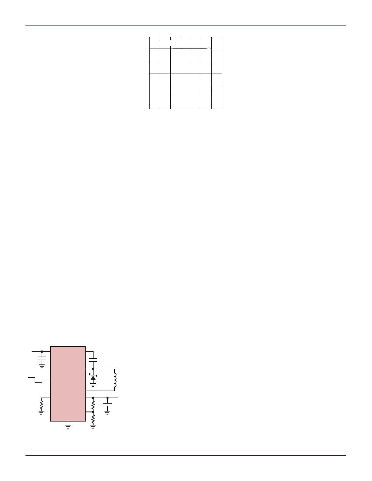
Figure 3. A LT3663 application producing
5V at 1.2A from an input of 7.5V to 36V. The
input is capable of handling 60V transients.
Linear Technology Magazine • March 2009
LT3653 programmed current limit, the
regulator’s output voltage decreases to
reduce charge current as the battery
charger enters dropout. If the system
load continues to increase, the battery
charge current first decreases to zero
and then reverses direction to deliver
power to the system load, supplementing the LT3653. The transitions
between these modes of operation are
seamless to the system load. The output current from the LT3653 regulator
Figure 2. The LT3663 output
current limit at 1.2A
Input overvoltage protection allows
the LT3653 to handle 60V input transients. The HVOK pin indicates that
the internal bias supplies are present
and no faults have occurred (i.e., overtemperature and input overvoltage
and undervoltage). The LT3653 includes internal compensation, and
an internal boost diode to minimize
the number of external components.
The LT3653 is available in an 8-lead
2mm × 3mm DFN package with an
exposed pad.
never exceeds the programmed output
current limit.
The LT3663 Directly
Accepts 36V Inputs
The LT3663 is a 1.5MHz constant
frequency, current mode control,
general purpose, monolithic switching regulator suited for automotive
batteries, industrial power supplies, distributed supplies, and wall
transformers. The LT3663 includes
a low current shutdown mode, input
overvoltage and undervoltage lockout,
and thermal shutdown. The LT3663 is
available in 8-lead (2mm × 3mm) DFN
package with exposed pad. An 8-lead
Charging a Single Cell Li-Ion
Battery from Either a USB
or High Voltage Input
Figure 1 shows a LT3653 and LTC4098
application charging a single cell Liion battery from either a USB input
or high voltage input. This solution
offers a seamless, highly efficient, low
part count approach to dual input
charging and power path control of a
Li-ion battery-powered application. If
additional integration is required for
more system supplies, the LT3653 can
be used in a similar fashion with the
LTC3576 PMIC.
When a high voltage input is applied, the LT3653 HVOK pin signals
the LTC4098 that it is capable of
delivering power. The LTC4098 takes
control of the LT3653’s VC pin and
MSOP package with exposed pad will
be available soon.
The LT3663 can also function as
a constant current, constant voltage
(CC/CV) source to charge a supercapacitor or other energy storage device.
The IC operates in constant current
mode at the programmed current
limit until the capacitor reaches the
programmed output voltage. It then
operates in a constant voltage mode
to maintain that voltage.
Figure 2 shows the LT3663 output current limit at 1.2A. For output
currents below 1.2A the regulator is
in constant voltage mode. When the
output current is increased to 1.2A it
goes into constant current mode. The
output current is maintained at 1.2A
from V
nominal down to 0V.
OUT
regulates the output voltage to just
above the battery voltage. This BatTrack function optimizes the battery
charger efficiency.
When present, the high voltage
input supplies the battery charge current and the system load current. If
the total current increases beyond the
7.5V–36V to 5V Buck
Regulator with 1.2A
Output Current Limit
Figure 3 shows a LT3663 application
producing 5V at 1.2A from an input
of 7.5V to 36V. The input is capable
continued on page 29
21
DESIGN FEATURES L
V V V
BE Q BE Q BE( ) ( )1 2
= =
dV
dT
dV
dT
mV
C
BE Q BE Q( ) ( )1 2
2
= =
°
V V
R
R
V
CTRL REF BE
= −
8
7
PTC
dV
dT
RRmV
C
CTRL
= = •
872
°
R
R
V
V
mV
CVdV dT
REF
BE
OUT
OUT
8
7
2
=
+ •
°
R
R
V
dV
dT
mV
C
V
mV
C
V
BE
OUT
OUT
REF
1
2
2
2
1=
• + •
•
°
°
−
dV
dT
dV
dT
mV
C
BE Q BE Q( ) ( )1 2
2
= =
°
TEMPERATURE (°C)
–50
V
APD
(V)
60
42
58
54
50
46
56
52
48
44
40
7525 125500 100–25
OUTPUT CURRENT (A)
0.1
EFFICIENCY (%)
100
90
80
70
60
50
40
0.5 0.90.3 0.7 1.1 1.3
VIN = 15V
VIN = 8V
VIN = 30V
Authors can be contacted
at (408) 432-1900
and expensive solution than typical
microprocessor-controlled methods.
The simplest scheme uses a resistor
divider from the V
pin to the CTRL
REF
pin, where the top resistor in the divider is an NTC (negative temperature
coefficient) resistor. While simple,
this method suffers from nonlinear
temperature coefficient of the NTC
resistor. A more precise method uses
a transistor network as shown in Figure 7. The PTC (Positive Temperature
Coefficient) of the CTRL pin voltage is
Figure 8. Temperature response
of the circuit shown in Figure 7
realized by an emitter follower of Q1
and a VBE multiplier of Q2.
Assuming:
and
then the CTRL pin voltage is
with
Given V
at room and dV
OUT
OUT
/DT,
the R1/R2 and R8/R7 can be calculated as follows
Resistors R5–R9 are selected to make
I(Q1) = I(Q2) ≈ 10µA, and
Simulation using LTspice always
gives a good starting point. The circuit
shown in Figure 7 is designed to have
V
= 50V (V
APD
dV
/dT = 100mV/°C (dV
APD
= 55V) at room and
OUT
OUT
/dT =
100mV/°C). The measured temperature response is shown in Figure 8,
which is very close to the design
target.
Conclusion
The LT3571 is a highly integrated,
compact solution to APD bias supply
design. It provides a useful feature set
and the flexibility to meet a variety of
challenging requirements, such as low
noise, fast transient response speed,
and temperature compensation. With
a high level of integration and superior performance, the LT3571 is the
natural choice for APD bias supply
design.
L
LT8410, continued from page 23
out of shutdown, the V
discharged for 70µs with a strong pull
down current, and then charged with
10µA to 1.235V. This achieves soft
start since the output is proportional
to V
. Full soft-start cycles occur
REF
even with short SHDN low pulses
since V
part is enabled.
In addition, the LT8410/-1 features
a 2.5V to 16V input voltage range, up
LT3653/63, continued from page 21
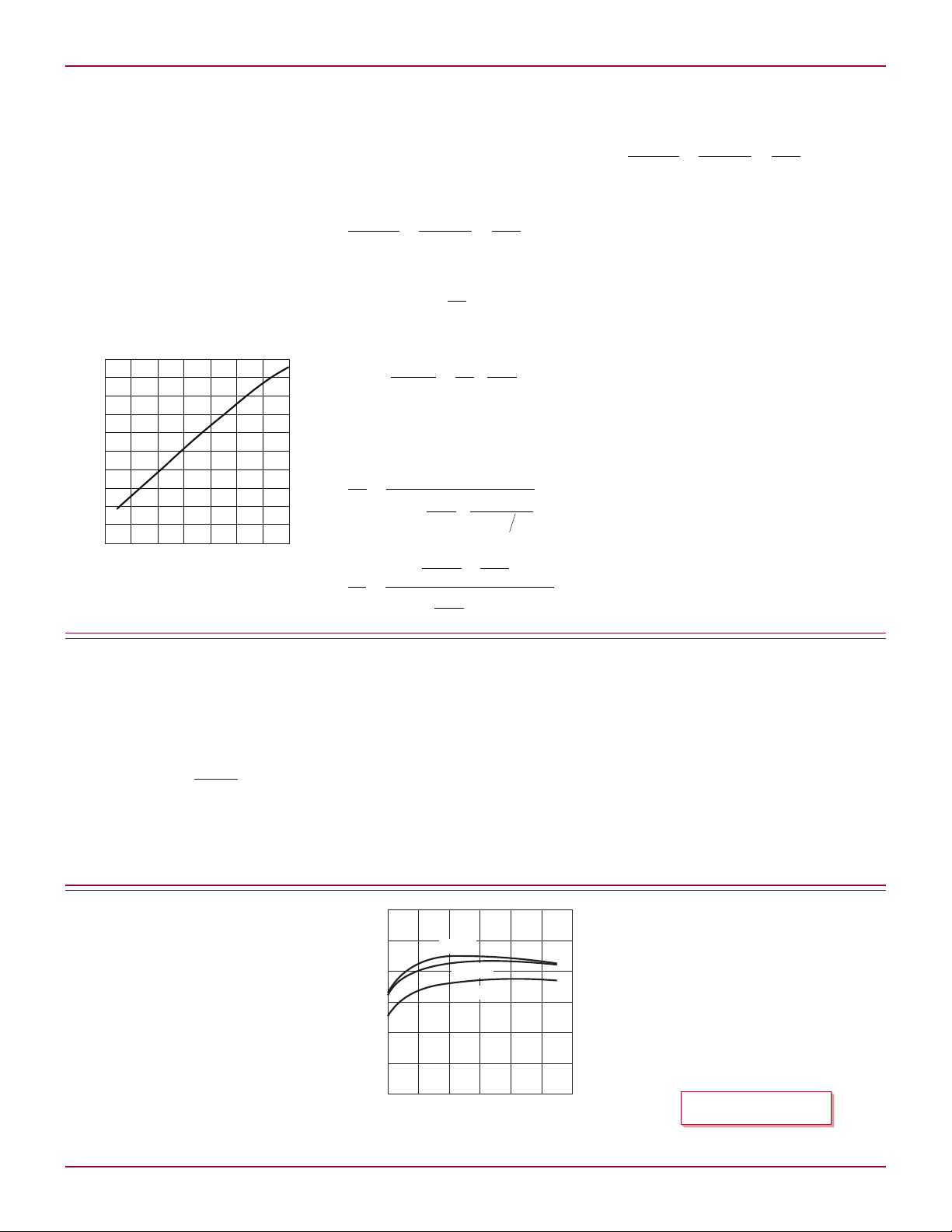
of handling 60V transients. Figure 4
shows the circuit efficiency at multiple
input voltages.
The current limit of the application
is set to 1.2A, therefore, the power path
components are sized to handle 1.2A
maximum. To reduce the application
footprint, the LT3663 includes internal
compensation and a boost diode. The
RUN pin, when low, puts the LT3663
into a low current shutdown mode.
Linear Technology Magazine • March 2009
pin is first
REF
is discharged when the
REF
to 40V output voltage and overvoltage
protection for CAP and V
OUT
.
Conclusion
The LT8410/-1 is a smart choice
for applications which require low
quiescent current and low input current. The ultralow quiescent current,
combined with high value integrated
feedback resistors, keeps the average
input current very low, significantly
Figure 4. Efficiency of the circuit in Figure 3
extending battery operating time.
Low current limit internal switches
(8mA for the LT8410-1, 25mA for the
LT8410) make the part ideal for high
impedance sources such as coin cell
batteries. The LT8410/-1 is packed
with features without compromising
performance or ease of use and is
available in a tiny 8-pin 2mm × 2mm
package.
L
Conclusion
The accurate programmable output
current limit of the LT3653 and
LT3663 eliminates localized heating
from an output overload, reduces the
maximum current requirements on the
power components, and makes for a
robust power supply solutions.
L
29
 Loading...