

Page 1
DESIGN FEATURES L
SW
V
IN
V
IN
7.5V TO 32V
(40 MAX)
CLP
RNG/SS
BOOST
SENSE
BAT
NTC
TIMER
CMPSH1-4
CMSH3-40MA
1µF
10µF
6.8µH
0.05Ω
10µF
LT3650-4.2
Li-Ion
CELL
+
SHDN
CHRG
FAULT
GND
Charge Li-Ion Batteries Directly
from High Voltage Automotive and
Industrial Supplies Using Standalone
Charger in a 3mm × 3mm DFN
Introduction
Growth of the portable electronics
market is in no small part due to the
continued evolution of battery capacities. For many portable devices,
rechargeable Li-Ion batteries are the
power source of choice because of their
high energy density, light weight, low
internal resistance, and fast charge
times. Charging these batteries safely
and efficiently, however, requires
a relatively sophisticated charging
system.
One additional problem faced by
battery charger designers is how to deal
with relatively high voltage sources,
such as those found in industrial
and automotive applications. In these
environments, system supply voltages exceed the input ranges of most
charger ICs, so a DC/DC step-down
converter is required to provide a local
low voltage supply for the charger IC.
The LT3650 standalone monolithic
switching battery charger does not
need this additional DC/DC converter.
It directly accepts input voltages up to
40V and provides charge currents as
high as 2A. It also includes a wealth
of advanced features that assure safe
battery charging and expand its applicability.
The LT3650 includes features that
minimize the overall solution size,
requiring only a few external components to complete a charger circuit. A
fast 1MHz switching frequency allows
the use of small inductors, and the IC
is housed inside a tiny 3mm × 3mm
DFN12-pin package. The IC has builtin reverse current protection, which
blocks current flow from the battery
back to the input supply if that supply
is disabled or discharged to ground,
so a single-cell LT3650 charger does
not require an external blocking diode
on the input supply.
A Charger Designed for
Lithium-Ion Batteries
A Li-Ion battery requires constantcurrent/constant-voltage (CC/CV)
charging system. A Li-Ion battery
is initially charged with a constant
current, generally between 0.5C and
1C, where C is the battery capacity
in ampere-hours. As it is charged,
the battery voltage increases until
it approaches the full-charge float
voltage. The charger then transitions
into constant voltage operation as
the charge current is slowly reduced.
The LT3650-4.1 and LT3650-4.2 are
designed to charge single-cell Li-Ion
by Jay Celani
batteries to float voltages of 4.1V and
4.2V, respectively. The LT3650-8.2
and LT3650-8.4 are designed to charge
2-cell battery stacks to float voltages
of 8.2V and 8.4V.
Once the charge current falls below
one tenth of the maximum constant
charge current, or 0.1C, the battery
is considered charged and the charging cycle is terminated. The charger
must be completely disabled after
terminating charging, since indefinite
trickle charging of Li-Ion cells, even at
miniscule currents, can cause battery
damage and compromise battery stability. A charger can top-off a battery
by continuing to operate as the current falls lower than the 0.1C charge
current threshold to make full use of
battery capacity, but in such cases a
backup timer is used to disable the
charger after a controlled period of
time. Most Li-Ion batteries charge fully
in three hours.
The LT3650 addresses all of the
charging requirements for a Li-Ion
battery. The IC provides a CC/CV
charging characteristic, transitioning
automatically as the requirements of
the battery change during a charging
cycle. During constant-current operation, the maximum charge current
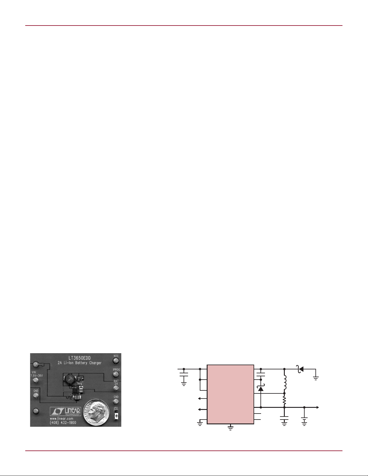
Figure 1. An LT3650 standalone battery
charger is small and efficient.
Linear Technology Magazine • June 2009
Figure 2. A single-cell 2A Li-Ion battery charger configured for C/10 charge termination
5
Page 2
L DESIGN FEATURES
I
BAT
(A)
0
EFFICIENCY (%)
80
90
100
70
60
0.5
1
1.5
2
VIN = 12V
VIN = 20V
V
BAT
(V)
CHARGE CURRENT (A)
1.0
1.2
1.4
1.6
1.8
2.0
0.6
0.8
0
0.2
0.4
3.0 3.22.6 2.8
3.4
3.8 4.0 4.23.6
FAULT
CHG
V
IN
10k
10k
LT3650
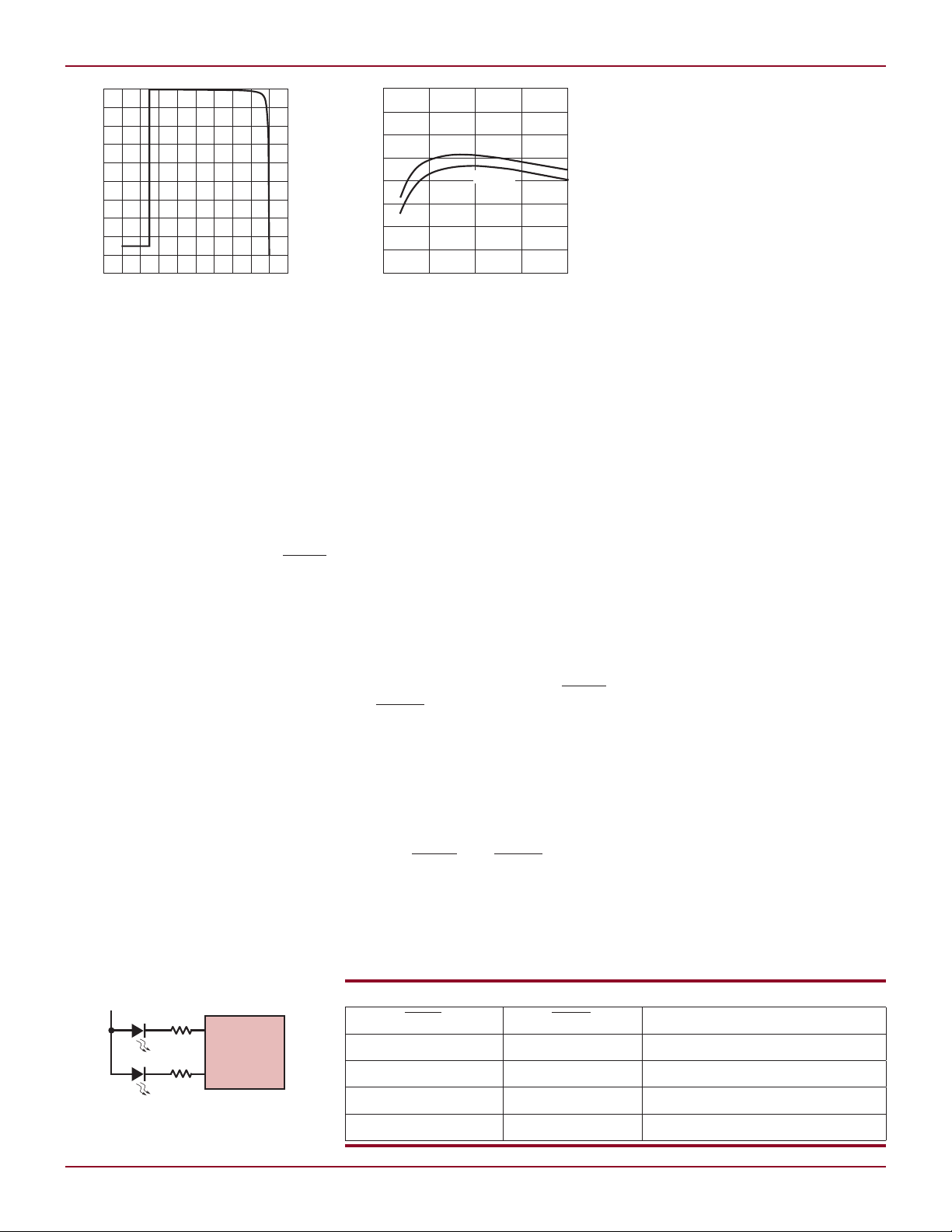
Figure 3. Battery charge current vs BAT pin
voltage for the charger shown in Figure 2
provided to the battery is programmable via a sense resistor, up to a
maximum of 2A. Maximum charge
current can also be adjusted using the
RNG/SS pin. The charger transitions
to constant-voltage mode operation as
the battery approaches the full-charge
float voltage. Power is transferred
through an internal NPN switch element, driven by a boosted drive to
maximize efficiency. A precision SHDN
pin threshold allows incorporation
of accurate UVLO functions using a
simple resistor divider.
Charge Cycle Termination
and Automatic Restart
A LT3650 charger can be configured
to terminate a battery charge cycle
using one of two methods: it can use
low charge current (C/10) detection,
enabled by connecting the TIMER
pin to ground, or terminate based on
the onboard safety timer, enabled by
connecting a capacitor to the TIMER
pin. After termination, a new charge
cycle automatically restarts should
the battery voltage fall to 97.5% of the
float voltage.
is selected, the LT3650 terminates
a charging cycle when the output
current has dropped to 1/10 of the
6
When C/10 termination mode
Figure 5. Visual charger status is
easily implemented using LEDs
A Basic Charger
Figure 2 shows a basic 2A single-cell
Li-Ion battery charger that operates
from a 7.5V to 32V input. Charging is
suspended if the input supply voltage
exceeds 32V, but the IC can withstand
input voltages as high as 40V without
damage. The 2A maximum charge
current corresponds to 100mV across
the 0.05
basic design does not take advantage
of the status pins, battery temperature
Figure 4. Power conversion efficiency vs
charger output current (I
charger shown in Figure 2
) for the battery
BAT
programmed maximum. In a 2A
charger, for example, the charge cycle
terminates when the battery charge
current falls to 200mA.
monitoring, or a safety timer features.
The battery charging cycle terminates
when the battery voltage approaches
4.2V and the charge current falls to
200mA. A new charge cycle is automatically initiated when the battery
voltage falls to 4.1V.
Timer termination, or top-off
charging, is enabled when a capacitor is connected to the TIMER pin.
The value of the capacitor sets the
safety timer duration—0.68µF corresponds to a 3-hour cycle time. When
timer termination is implemented,
the charger continues to operate in
constant-voltage mode when charge
currents fall below C/10, allowing additional low current charging to occur
until the timer cycle has elapsed, thus
maximizing use of the battery capacity.
During top-off charging, the CHRG
and FAULT status pins communicate
“charge complete.” At the end of the
timer cycle, the LT3650 terminates
the charging cycle.
After charge cycle termination, the
LT3650 enters standby mode where
the IC draws 85µA from the input sup
ply and less than 1µA from the battery.
Both the CHRG and FAULT pins are
high impedance during standby mode.
Should the battery voltage drop to
97.5% of the float voltage, the LT3650
automatically restarts and initializes
a new charging cycle.
Table 1. Status pin state and corresponding operating states
CHRG FAULT Charger Status
High Impedance High Impedance Standby/Shutdown/Top-off
Low High Impedance CV/CC Charging (>C/10)
High Impedance Low Bad Battery Detected
Low Low Temperature Fault
Safety Features:
Preconditioning,
Bad Battery Detection,
and Temperature Monitor
Li-Ion batteries can sustain irreversible damage when deeply discharged,
so care must be taken when charging
such a battery. A gentle preconditioning charge current is recommended to
activate any safety circuitry in a battery
pack and to re-energize deeply discharged cells, followed by a full charge
cycle. If a battery has sustained damage from excessive discharge, however,
the battery should not be recharged.
Deeply discharged cells can form
copper shunts that create resistive
shorts, and charging such a damaged
battery could cause an unsafe condi-
-
tion due to excessive heat generation.
Should a deeply discharged battery be
encountered, a battery charger must
be intelligent enough to determine
whether or not the battery has sustained deep-discharge damage, and
avoid initiating a full charge cycle on
such a damaged battery.
Ω external sense resistor. This
Linear Technology Magazine • June 2009
Page 3

DESIGN FEATURES L
CLP
SYSTEM LOAD
INPUT SUPPLY
V
IN
R
CLP
LT3650
SW
V
IN
CLP
RUN/SS
BOOST
SENSE
BAT
NTC
TIMER
1N914
CMSH3-40MA
SYSTEM LOAD
1µF
6.8µH
0.057
LT3650-X
GND
10µF
Li-Ion
CELL
10k
INPUT SUPPLY
12V TO 32V
(40V MAX)
BZX384-C9V1
(9.1V)
10µF
10µF
0.05Ω
SHDN
CHRG
FAULT
10k
36k
3k
10k
0.68µF
+
0.1µF
The LT3650 employs an automatic
precondition mode, which gracefully
initiates a charging cycle into a deeply
discharged battery. If the battery voltage is below the precondition threshold
of 70% of the float voltage, the maximum charge current is reduced to 15%
of the programmed maximum (0.15C)
until the battery voltage rises past the
precondition threshold.
If the battery does not respond
to the precondition current and the
battery voltage does not rise past the
temperature, and suspends charging
should the temperature fall outside of
the safe charging range.
precondition threshold, a full-current
charge cycle does not initiate.
If the safety timer is used for ter mination, the LT3650 also enables
deep-discharge damage detection
and incorporates a “bad battery”
detection fault. Should the battery
voltage remain below the precondition threshold for 1/8 of the charge
cycle time (typically 22.5 minutes), the
charger suspends the charging cycle
and signals a “bad battery” fault on
the status pins. The LT3650 main
tains this fault state indefinitely, but
automatically resets itself and starts
a new charging cycle if the damaged
battery is removed and another battery
is connected.
Li-Ion batteries have a relatively
narrow temperature range where they
can be safely charged. The LT3650
has a provision for monitoring battery
Figure 7. A single cell Li-Ion 2A battery charger with 3 hour safety timer termination, LED status
indicators, temperature sensing, low input voltage charge current foldback, and input supply
current limit
Linear Technology Magazine • June 2009
is enabled by connecting a 10k (B =
3380) NTC thermistor from the IC’s
NTC pin to ground. This thermistor
must be in close proximity to the battery, and is generally housed in the
battery case. This function suspends a
charging cycle if the temperature of the
thermistor is greater than 40°C or less
than 0°C. Hysteresis corresponding to
5°C on both thresholds prevents mode
glitching. Both the CHRG and FAULT
-
status output pins are pulled low during a temperature fault, signaling that
the charging cycle is suspended. If the
safety timer is used for termination,
the timer is paused for the duration
of a temperature fault, so a battery
receives a full-duration charging cycle,
even if that cycle is interrupted by
the battery being out of the allowed
temperature range.
Figure 6. R
supply current limit
Under/overtemperature protection
sets the input
CLP
Status Indicator Pins
The status of a LT3650 charger is communicated via the state of two pins:
CHRG and FAULT. These status pins
are open-collector pull-down, reporting the operational and fault status of
the battery charger. CC/CV charging
is indicated while charge currents are
greater than 1/10 the programmed
maximum charge current. The status
pins also communicate bad battery
and battery temperature fault states.
Table 1 shows a fault-state matrix for
these two pins.
The status outputs can be used as
digital status signals in processorcontrolled systems, and/or connected
to pull current through an LED for
visual status display. The status pins
can sink currents up to 10mA and can
handle voltages as high as 40V, so a
visual display can be implemented by
simply connecting an LED and series
resistor to VIN.
Maximum Charging Current
Programming and Adjustment
Maximum charge current is set using an external sense resistor placed
between the BAT and SENSE pins of
the LT3650. Maximum charge current
corresponds to 100mV across this resistor. The LT3650 supports maximum
charge currents up to 2A, corresponding to a 0.05
The LT3650 includes two control
pins that allow reduction of the programmed maximum charge current.
The RNG/SS pin voltage directly affects the maximum charge current
such that the maximum voltage allowed across the sense resistor is 1/10
the voltage on RNG/SS for RNG/SS
< 1V. This pin sources a constant
50µA, so the voltage on the pin can
be programmed by simply connecting
a resistor from the pin to ground. A
capacitor tied to this pin generates a
voltage ramp at start-up, creating a
soft-start function. The pin voltage can
be forced externally for direct control
over charge current.
The IC includes a PowerPath™
control feature, activated via the CLP
pin, which acts to reduce battery
charge current should the load on a
Ω sense resistor.
continued on page 38
7
Page 4

L NEW DEVICE CAMEOS
CURRENT (A)
0.5
0.6
0.7
0.8
0.9
1.0
0.3
0.4
0
0.1
0.2
0.5
0.6
0.7
0.8 0.9
1.0
0.3
0.4
0
0.1
0.2
INPUT
SUPPLY
CURRENT
VIN = 24V
CHARGER
INPUT
CURRENT
SYSTEM LOAD CURRENT (A)
VIN (V)
I
OUT(MAX)
(A)
I
IN
(A)
1.0
1.2
1.4
1.6
1.8
2.0
0.6
0.8
0
0.2
0.4
0.25
0.30
0.35
0.40
0.45
0.50
0.15
0.20
0
0.05
0.10
16 181210 32 4014
20
24 26 3022
I
OUT(MAX)
I
INPUT
The LT5581’s RMS measurement capability provides accurate RF power
readings to within ±0.2dB regardless
of waveforms that have high crest-factor modulated content, multicarrier
or multitone. Moreover, the LT5581
offers exceptional accuracy of ±1dB
over its operating temperature range
of –40°C to 85°C.
Operating over a wide supply voltage
range of 2.7V to 5.25V, the LT5581’s
low power consumption makes it ideal
for battery-powered communication
LT3650, continued from page 7
monitored input supply become excessive. The CLP pin can be configured
to implement an input current limit
function for systems having multiple
loads that share the LT3650 V
sup-
IN
ply. The LT3650 reduces maximum
battery charge current if the voltage
on the CLP pin exceeds the voltage on
VIN by 50mV. Total load current on the
input power supply can be monitored
by connecting a sense resistor from the
CLP pin to VIN, and connecting any external loads to the VIN pin. The LT3650
servos the charger maximum output
current such that 50mV is maintained
across the CLP sense resistor.
A Full Complement of
Battery Charger Features
Figure 7 shows a battery charger that
incorporates many of the LT3650’s
unique features. This charger incor-
and multimedia devices. Yet, it has
the accuracy performance to meet the
performance required by basestations,
picocells and femtocells, cable infrastructure and optical communication
systems. Additionally, the LT5581’s
wide frequency range extends to
applications including WiMAX and
wireless systems in the 5GHz ISM
bands. The LT5581’s single-ended RF
input does not require an external RF
transformer, thus simplifying the application design while reducing costs.
porates top off charging with a 3-hour
backup safety timer, and directly
accepts input voltages from 12V to
40V (32V operating maximum). This
charger uses a 9.1V Zener diode to
level-shift the input supply, incorporating an undervoltage lockout
function for VIN < 10V.
Battery pack temperature-sensing is enabled by connecting an NTC
thermistor to the NTC pin. Charging is
suspended if the battery temperature
does not remain within a 0°C to 40°C
range. The charger uses a resistor
divider to modulate the voltage on
RNG/SS, which reduces the maximum
battery charge current if VIN is below
20V, useful for current-limited input
sources such as wall adapters. A capacitor on the RNG/SS pin enables
a soft-start function. A secondary
system load is supported, with the
input supply protected by an input
The LT5581 has a fast response time
of 1µs rise time to a full power swing,
suitable for time-division duplexing
systems.
The LT5581 also incorporates a
shutdown feature. When the LT5581’s
Enable input pin is pulled low, the chip
draws a typical shutdown current of
0.2µA, and a maximum of 6µA. The
device is offered in a tiny 8-lead, 3mm
× 2mm DFN surface mount package.
L
current limit feature, incorporated
by connecting the input supply to the
CLP pin via a 0.05
Ω sense resistor. The
maximum charge current is automatically reduced to keep the total input
supply current from exceeding the 1A
limit set by the sense resistor.
Conclusion
The LT3650 provides a versatile and
easy-to-use platform for a wide variety
of efficient Li-Ion battery charger solutions. Low power dissipation makes
continuous charging up to 2A practical, deriving power directly from input
supplies up to 32V without the need
for an intermediate DC/DC converter.
The compact size of the IC coupled with
modest external component requirements allows construction of space
saving, cost-effective, and feature-rich
Li-Ion battery chargers.
L
Figure 8. Charger maximum input current (IIN) and maximum output
current (I
7. Charge current reduction for V
supply current below 0.5A
38
38
OUT(MAX)
) vs VIN for the battery charger shown in Figure
< 20V keeps the charger input
IN
Figure 9. Charger maximum input current, system load current, and total
input supply current for the battery charger shown in Figure 7 for V
24V. Battery charger output current is reduced to maintain a maximum
input supply current of 1A, which corresponds to 50mV across the 0.05Ω
resistor that is connected between the CLP and V
Linear Technology Magazine • June 2009
pins of the LT3650.
IN
IN
=
 Loading...