

L DESIGN FEATURES
LT3480
GND
C8
100pF
C6
680pF
C3
2.2µF
50V
C7
0.1µF
50V
C1
0.47µF
L1*
10µH
D1
DFLS240L-7
C4
22µF
10V
R5
20k
R2
110k
R6
100k
R1
56.2k
R3
590k
E5
E1
V
OUT
5V, 2A
E7
R4
100k
PGOOD
BD
* L1: SUMIDA CDR7D43MNNP-100NC
BOOST
SW
V
IN
V
IN
6.3V TO 38V
TRANSIENT
TO 60V
0V
5V
RUN/SS
RT
V
C
FB
PGOOD
SYNC
1
2
3
4
5
10
11
9
8
7
6
Tiny High Efficiency 2A Buck
Regulator Directly Accepts
Automotive, Industrial and
Other Wide Ranging Inputs
Introduction
Automotive batteries, industrial power
supplies, distributed supplies and
wall transformers are all sources of
wide-ranging, high voltage inputs. The
easiest way to step down these sources
is with a high voltage monolithic stepdown regulator that can directly accept
a wide input range and produce a
well-regulated output. The LT3480 is a
new step-down regulator that accepts
input from up to 38V (60V transient)
while providing excellent line and load
regulation and dynamic response. The
LT3480 offers high efficiency solutions
over wide load range and keeps the
output ripple low during Burst Mode®
operation.
LT3480 Features
Available in either a 10-pin MSOP
or a 3mm × 3mm DFN package, the
LT3480 offers an integrated 3.5A
power switch and external compensation for design flexibility. The LT3480
employs a constant frequency, current
mode architecture. The switching frequency can be set between 250kHz and
2.4MHz by using a resistor tied from
the RT pin to ground. This allows a
trade off between component size and
efficiency. The switching frequency
can be synchronized to an external
clock for noise sensitive applications.
An external resistor divider programs
The LT3480 is a new
step-down regulator that
accepts input from up to
38V (60V transient).
the output voltage to any value above
the part’s 0.8V reference.
The LT3480 offers soft-start via a
resistor and capacitor on the RUN/SS
pin, thus reducing maximum inrush
currents during start-up. The LT3480
can withstand a shorted output. A
cycle-by-cycle internal current limit
protects the circuit in overload and
limits output power; when the output
voltage is pulled to ground by a hard
short, the LT3480 reduces its operating frequency to limit dissipation
and peak switch current. This lower
frequency allows the inductor current
to safely discharge, thus preventing
current runaway.
diode is integrated into the IC to minimize solution size and cost. When the
output voltage above 2.5V, the anode
of the boost diode can be connected to
output. For output voltages lower than
2.5V, the boost diode can be tied to a
separate rail or to the input (<28V). For
systems that rely on a well-regulated
power source, the LT3480 provides
a power good flag that signals when
V
output voltage.
Modes of Operation:
Low Ripple Burst and
Forced Continuous
Two modes of operation can be selected through the SYNC pin. Applying
a logic low to the SYNC pin enables
low ripple Burst Mode operation,
which maintains high efficiency at
light load while keeping the output
voltage ripple low. During Burst Mode
by Kevin Huang
The high side bootstrapping boost
reaches 90% of the programmed
OUT
18
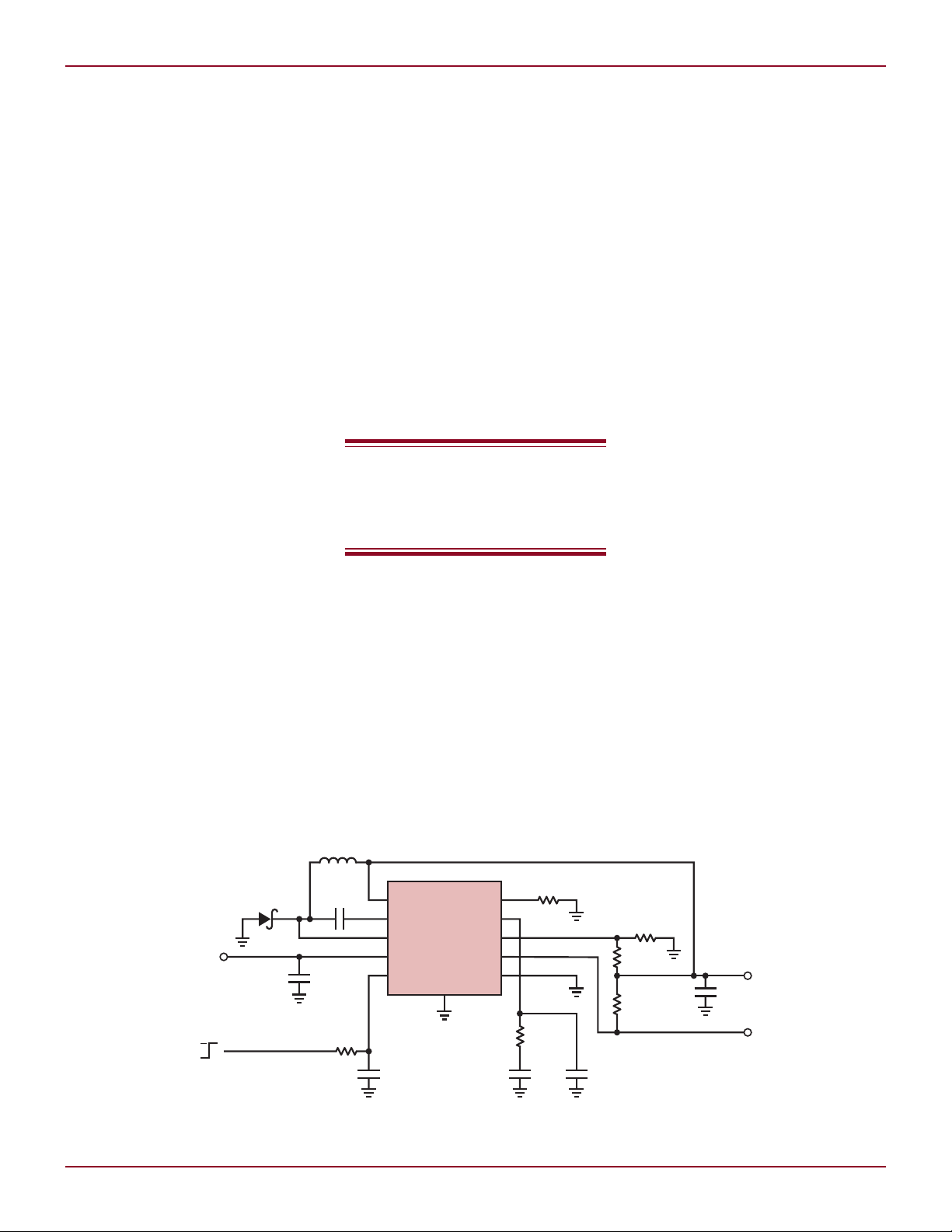
Figure 1. A 600kHz 6.3V–38V input DC/DC Converter using the LT3480 delivers 2A at 5V output.
Linear Technology Magazine • March 2007
DESIGN FEATURES L
LOAD CURRENT (mA)
0
EFFICIENCY (%)
50
500 1000 1500 2000
60
100
90
80
70
VIN = 12V
5µs/DIV
V
OUT
10mV/DIV
I
L
0.2A/DIV
200µs/DIV
V
OUT
2V/DIV
I
L
2A/DIV
LT3480
GND
C8
100pF
C6
680pF
C3
2.2µF
50V
C7
0.1µF
C1
0.47µF
L1*
2.2µH
D1
DFLS240L-7
C4
10µF
10V
R5
20k
R2
110k
R6
100k
R1
11.5k
R3
590k
E5
E1
V
OUT
5V, 2A
E7
R4
100k
PGOOD
BD
* L1: SUMIDA CDRH4D22/HP-2R2NC
BOOST
SW
V
IN
V
IN
9V TO 22V
60V TRANSIENT
0V
5V
RUN/SS
RT
V
C
FB
PGOOD
SYNC
1
2
3
4
5
10
11
9
8
7
6
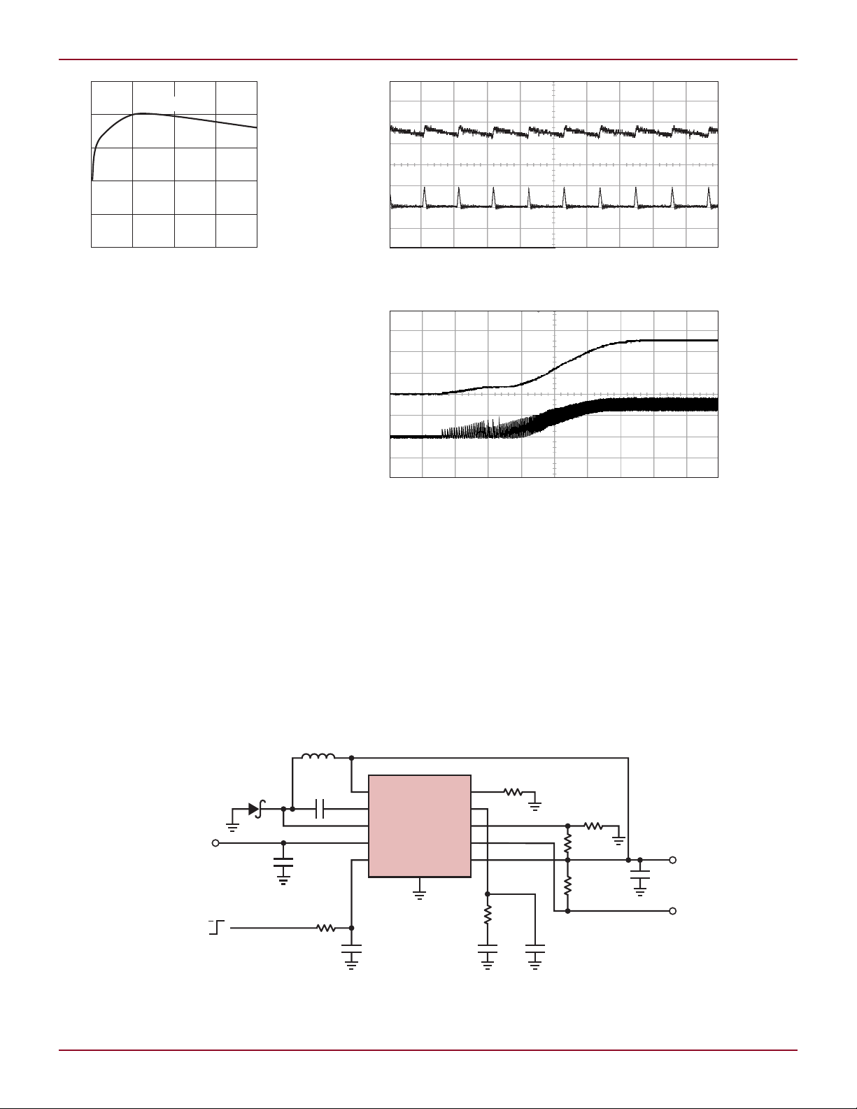
Figure 2. Efficiency for circuit in Figure 1
operation, the LT3480 delivers single
cycle bursts of current to the output
capacitor followed by sleep periods
when the output power is delivered to
the load by the output capacitor. Between bursts, all circuitry associated
with controlling the output switch is
shut down, reducing the input supply
current and BD quiescent current to
30µA and 80µA respectively. As the
load current decreases to a no load
condition, the percentage of time
that LT3480 operates in sleep mode
increases and the average input current is greatly reduced, resulting in
high efficiency. The LT3480 has a very
low (less than 1µA) shutdown current
which significantly extends battery
life in applications that spend long
periods of time in sleep or shutdown
mode. For applications that require
constant frequency operation even at
no load, the LT3480 can be put into
Figure 3. LT3480 Burst Mode operation at 10mA load
Figure 4. Soft-start of LT3480
forced continuous mode operation by
tying the SYNC pin above 2.5V.
6.3V–38V to 5V, 2A DC/DC
Converter with All Ceramic
Capacitors
Figure 1 shows the LT3480 producing 5V at 2A from an input of 6.3V to
38V with 60V transient. The circuit is
programmed for a 600kHz switching
frequency. Figure 2 shows the circuit
efficiency at 12V input. The efficiency
peaks at 90% and remains high across
the entire load range. The SYNC pin
is tied to the ground to enable Burst
Mode operation and achieve high efficiency at light load. Figure 3 shows the
inductor current and output voltage
ripple under single pulse Burst Mode
operation at 10mA load. The output
Figure 5. High operating frequency allows the use of small inductors and capacitors.
This 2MHz, 9V–22V input DC/DC converter using the LT3480 delivers 2A at 5V output.
Linear Technology Magazine • March 2007
19

L DESIGN FEATURES
LT3480
GND
C8
100pF
C6
680pF
C10
22µF
10V
C3
2.2µF
50V
C7
0.1µF
C9
10µF
10V
C1
0.47µF
L1A*
10µH
D1
DFLS240L-7
C4
22µF
10V
R5
20k
R2
110k
R6
100k
R1
60.4k
R3
590k
E1
V
OUT1
5V, 1A
V
OUT2
–5V, 0.5A
R4
100k
PGOOD
BD
* L1: COOPER ELECTRONIC DRQ74-100
BOOST
SW
V
IN
V
IN
6.3V TO 38V
0V
5V
RUN/SS
RT
V
C
FB
PGOOD
SYNC
1
2
3
4
5
10
11
9
8
7
6
L1B*
10µH
D2
DFLS240L
LT3685
GND
C8
100pF
C6
680pF
C3
2.2µF
50V
C7
0.1µF
C1
0.47µF
L1*
2.2µH
D1
DFLS240L-7
C4
10µF
10V
R5
20k
R2
110k
R6
100k
R1
11.5k
R3
590k
E5
E1
V
OUT
5V, 2A
E7
R4
100k
PGOOD
BD
* L1: SUMIDA CDRH4D22/HP-2R2NC
BOOST
SW
V
IN
V
IN
9V TO 22V
60V TRANSIENT
0V
5V
RUN/SS
RT
V
C
FB
PGOOD
SYNC
1
2
3
4
5
10
11
9
8
7
6
Figure 6. A 2MHz 9V–22V input DC/DC converter using the LT3685 delivers 2A at 5V output.
voltage ripple V
is less than 10mV
P–P
as a result of low ripple Burst Mode
operation.
An external signal can drive the
RUN/SS pin through a resistor and
capacitor to program the LT3480’s
soft-start, reducing maximum inrush
current during start-up. Figure 4
shows the start-up waveform.
2MHz, 9V–22V to 5V, 2A
DC/DC Converter with All
Ceramic Capacitors
Figure 5 shows a step-down DC/DC
converter using all ceramic capacitors.
This circuit provides a regulated 5V
output at up to 2A from an input of
9V to 22V. The high 2MHz switching
frequency allows the use of small
inductor and capacitors.
In typical automotive batteryvoltage applications, high voltage
line transients, such as during a
load-dump condition, must be accommodated. The circuit shown in Figure 5
can operate through intermittent high
voltage excursions to 60V. This converter is an ideal choice for operation
near an AM radio receiver because it
operates above the broadcast band
and the switching noise can be filtered
in a predictable manner. The SYNC
pin is tied to output to disable Burst
Mode operation in order to eliminate
AM band interference. The efficiency
of this circuit reaches 85%.
The LT3685, similar to the LT3480
without Burst Mode operation, is also
20
a good candidate for this application.
Figure 6 shows the circuit using the
LT3685 for this application.
negative output tracks the positive
output within 5%. For a more complete
description of this circuit, see Linear
Technology Design Note 100.
Dual Output Converter
Dual output supplies are required
for many applications. The circuit in
Figure 7 uses an LT3480 to generate
both positive and negative 5V supplies.
The two inductors shown are actually
two windings on a coupled inductor.
The load current on the positive output
should be larger than the load on the
negative output. With this restriction
satisfied, the voltage magnitude of the
Figure 7. A ±5V dual output DC/DC converter. As long as the load on the negative channel is less
than the load on the positive channel, the voltage magnitude of the negative output tracks the
positive output within 5%.
Conclusion
The wide input range, low quiescent
current, small size and robustness
of the LT3480 make it an easy fit in
automotive, industrial and distributed
power applications. It is highly efficient
over the entire load range. Its unique
low ripple Burst Mode operation helps
to save battery power life while maintaining low output ripple.
Linear Technology Magazine • March 2007
L
 Loading...