

Page 1
advertisement
ThinSOT Switching Regulator Controls Inrush Current
Design Note 365
Jesus Rosales
Introduction
Inrush current can be troublesome, especially when regulators are operated from batteries or a current-limited
source. In such cases, excessive inrush current can cause
the input source to collapse and prevent the converter
from ever starting up. Inrush current can also trip input
line fuses or cause the output to overshoot. There are
many ways to deal with this problem, but most of them are
difficult to implement or have undesirable side effects,
often making the cure worse than the cause.
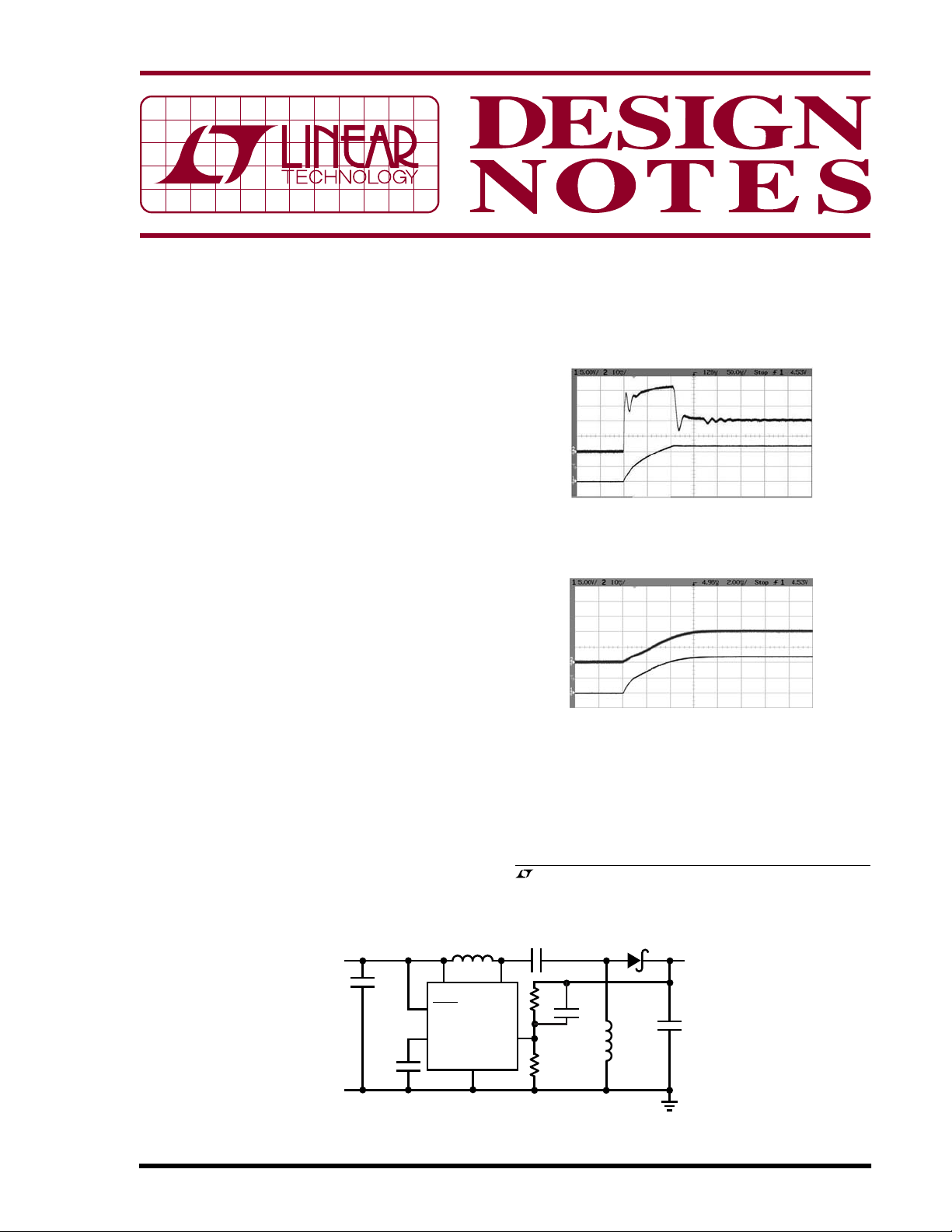
I
IN
0.2A/DIV
V
OUT
5V/DIV
50µs/DIV
Figure 2. Input Current and Output Voltage at Turn-On
Without CSS Capacitor for Figure 1 Circuit
DN365 F02
A Simple Solution
Figure 1 shows a solution to this problem using the
®
LT
3467 in a 10V-16V input to 12V/300mA output SEPIC
converter. The LT3467 ThinSOT
TM
switching regulator
integrates a soft-start function with a built-in 42V, 1.1A
switch. Figures 2 and 3 illustrate the effect that the
LT3467’s soft-start feature has on inrush currents.
Figure 2 shows the start-up waveforms for the Figure 1
circuit with the SS feature disabled (by removing C
SS
from
the SS pin). The inrush current in this case is limited only
by the maximum duty cycle or maximum switch current
of the LT3467. The top trace shows input current and the
bottom trace shows output voltage. It takes only about
100µs for the output to go from 0V to 12V, requiring an
input current of about 0.85A peak, thus exceeding the
nominal steady-state level.
L1
10µH
V
10V TO 16V
GND
IN
2.2µF
25V
C
SS
0.1µF
Figure 1. 10VIN-16VIN to 12V at 300mA SEPIC Converter
CLS62-100
61
V
IN
4
SHDN
LT3467
5
SS
GND
2
•
SW
FB
I
IN
0.2A/DIV
V
OUT
5V/DIV
2ms/DIV
DN365 F03
Figure 3. Input Current and Output Voltage at Turn-On
with CSS Capacitor for Figure 1 Circuit
Figure 3 shows the same waveforms with a 0.1µF capaci-
tor connected to the SS pin. Now, both input current and
output voltage rampup in a controlled fashion and settle
, LTC and LT are registered trademarks of Linear Technology Corporation.
ThinSOT is a trademark of Linear Technology Corporation.
16V
1µF
115k
3
13.3k
10pF
B0530W
•
L1B
10µH
CLS62-100
DN365 F01
V
OUT
12V
300mA
4.7µF
16V
06/05/365
Page 2
comfortably into their respective steady-state levels. By
using only one small capacitor between the SS pin and
ground, inrush current has been eliminated. Figure 4
shows an efficiency curve for the SEPIC converter of
Figure 1.
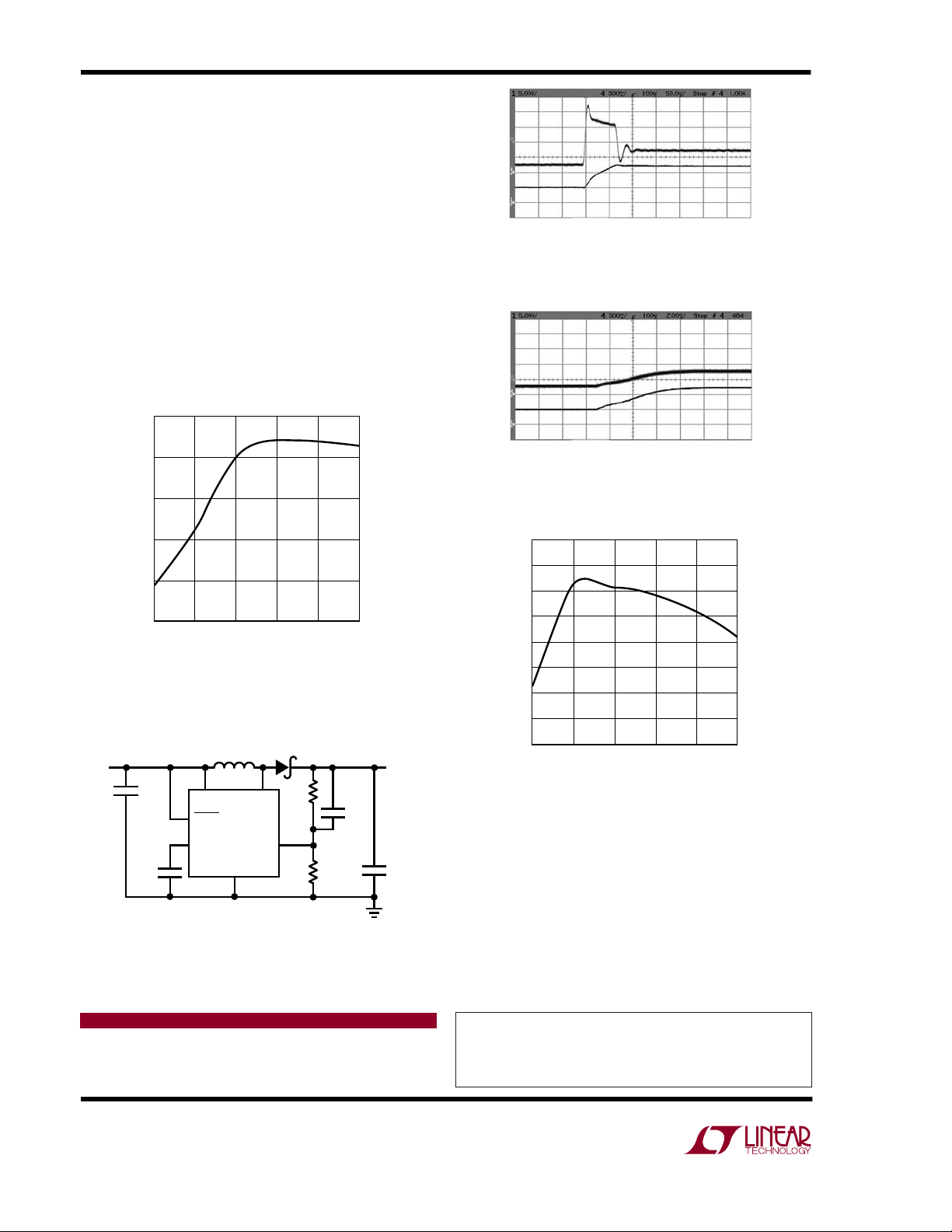
Figure 5 shows a boost converter that provides 12V at
300mA from a 5V input source. Figures 6 and 7 show the
input and output currents, with and without the soft-start
feature enabled. Figure 6 shows that without soft-start,
even though the output voltage follows the input by
conducting through the inductor and diode, there is an
inrush of current which exceeds 2A at the point where the
converter begins to switch. Figure 7 shows the improved
start-up results with soft-start enabled. Figure 8 shows
the efficiency of the circuit.
82
I
IN
0.5A/DIV
V
OUT
5V/DIV
50µs/DIV
DN365 F06
Figure 6. Input Current and Output Voltage at Turn-On
Without C
I
0.5A/DIV
V
OUT
5V/DIV
Capacitor for Figure 5 Circuit
SS
IN
81
80
79
EFFICIENCY (%)
78
77
100
50
LOAD CURRENT (mA)
150
200
250
300
DN365 F04
Figure 4. SEPIC Converter Efficiency for Figure 1 Circuit
10µH
GND
B0530W
115k
SW
3
FB
13.3k
2
DN365 F07
10pF
V
OUT
12V
300mA
4.7µF
16V
V
IN
5V
2.2µF
C
SS
0.1µF
CR43-100
61
V
IN
4
SHDN
LT3467
5
SS
Figure 5. 5VIN to 12V at 300mA BOOST Converter
2ms/DIV
DN365 F07
Figure 7. Input Current and Output Voltage at Turn-On
with CSS Capacitor for Figure 5 Circuit
90
89
88
87
86
85
EFFICIENCY (%)
84
83
82
100 150 250
50
LOAD CURRENT (mA)
200
300
DN365 F08
Figure 8. BOOST Converter Efficiency
for Figure 5 Circuit
Conclusion
Countless hours can be spent looking for ways to control
inrush current or just getting the output to come up. The
LT3467 provides a simple solution. The addition of a
single, tiny, low cost capacitor can make the difference
between a smooth design cycle or a laborious one.
Data Sheet Download
http://www.linear.com
Linear Technology Corporation
1630 McCarthy Blvd., Milpitas, CA 95035-7417
(408) 432-1900 ● FAX: (408) 434-0507 ● www.linear.com
For applications help,
call (408) 432-1900, Ext. 2759
dn365f LT/TP 0605 305K • PRINTED IN THE USA
© LINEAR TECHNOLOGY CORPORATION 2005
 Loading...