


FEATURES
■
Input Offset Voltage: 75µV (Max)
■
60V Supply Operation (LT1787HV)
■
12-Bit Dynamic Range
■
Operating Current: 60µA
■
User-Selectable External Sense Resistor
■
Bidirectional High Side Current Sensing
■
Unidirectional or Bidirectional Output
■
Input Noise Filtering
■
Available in 8-Lead SO and MSOP Packages
U
APPLICATIO S
■
Battery Monitoring
■
Power Monitoring
■
Portable Phones
■
Cellular Phones
■
Portable Test/Measurement Systems
■
Battery-Operated Systems
LT1787/LT1787HV
Precision, High Side
Current Sense Amplifiers
U
DESCRIPTIO
The LT®1787 is a complete micropower precision high
side current sense amplifier. The LT1787 monitors bidirectional currents via the voltage across an external sense
resistor. A current or voltage output depicts the direction
and magnitude of the sense current. The LT1787 delivers
greater than a 12-bit dynamic range with ultralow 40µV
input offset voltage compared to a typical 250mV fullscale input voltage. A fixed gain of 8 is set by onboard
precision resistors. Input signal filtering is easily implemented with a capacitor between the FIL– and FIL+ pins.
The LT1787HV operates from 2.5V to 60V total supply
voltage and the LT1787 operates from 2.5V to 36V total
supply voltage. Both versions have a PSRR in excess of
120dB. The LT1787/LT1787HV draw only 60µA and are
available in 8-lead SO and MSOP packages.
, LTC and LT are registered trademarks of Linear Technology Corporation.
U
TYPICAL APPLICATIO
12-Bit Dynamic Resolution Unidirectional Output into LTC®1286 ADC
R
SENSE
FIL
V
S
DNC
V
EE
LOAD
–
LT1787HV
–
• R
0.0016Ω
SENSE
V
R
20k
V
)
FIL
V
BIAS
OUT
OUT
S
+
+
0.1µF
2.5V TO 60V
R1
15k
V
REFVCC
+IN
–IN
C2
LT1634-1.25
LTC1286
GND
1µF
D
C1
CS
CLK
OUT
LOAD
V
OUT
TO
= V
I = 100A
18
27
36
45
+ (8 • I
BIAS
TO µP
1787 TA01
Input Offset Voltage vs Supply Voltage
50
40
30
20
5V
10
0
–10
–20
–30
INPUT OFFSET VOLTAGE (µV)
–40
–50
10
0
20
TOTAL SUPPLY VOLTAGE (V)
30 40
50
1787 TA01b
60
1
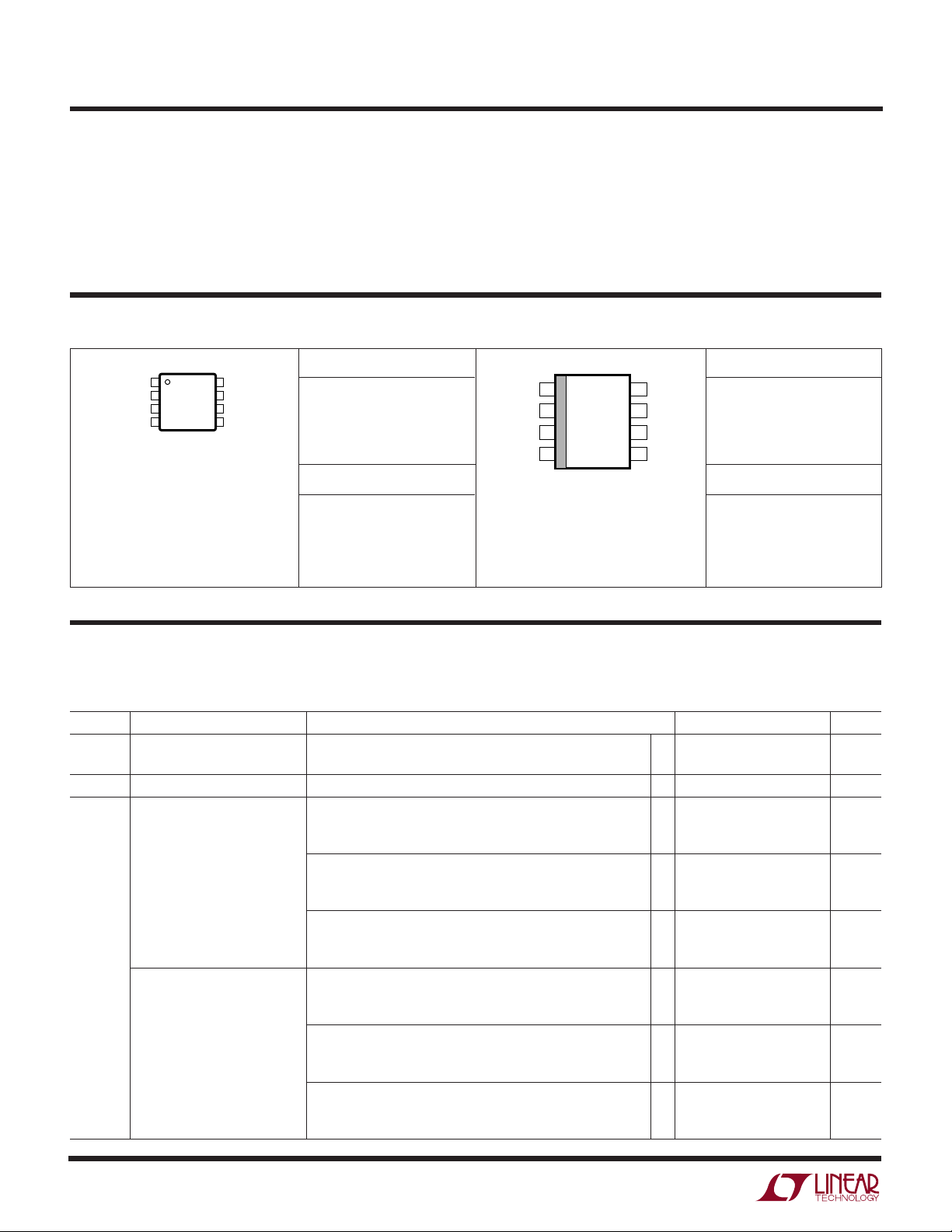
LT1787/LT1787HV
1
2
3
4
8
7
6
5
TOP VIEW
MS8 PACKAGE
8-LEAD PLASTIC MSOP
FIL
+
V
S
+
V
BIAS
V
OUT
FIL
–
V
S
–
DNC*
V
EE
WW
W
ABSOLUTE MAXIMUM RATINGS
U
(Notes 1, 2)
Differential Sense Voltage...................................... ±10V
Total Supply Voltage (LT1787) ................................ 40V
Total Supply Voltage (LT1787HV) ........................... 65V
Output Voltage..................... (VEE – 0.3V) to (VEE + 35V)
Output Bias Voltage .............(VEE – 0.3V) to (VEE + 35V)
U
W
PACKAGE/ORDER INFORMATION
ORDER PART NUMBER
LT1787CMS8
LT1787IMS8
LT1787HVCMS8
LT1787HVIMS8
* DO NOT CONNECT
T
= 150°C, θJA = 250°C/W
JMAX
MS8 PART MARKING
LTGM
LTGN
LTKJ
LTKK
Operating Temperature Range ................ –40°C to 85°C
Specified Temperature Range (Note 3)... – 40°C to 85°C
Storage Temperature Range ..................–65°C to 150°C
Lead Temperature (Soldering, 10 sec)..................300°C
U
FIL
V
DNC*
V
–
1
–
2
S
3
4
EE
T
JMAX
8-LEAD PLASTIC SO
* DO NOT CONNECT
TOP VIEW
8
7
6
5
S8 PACKAGE
= 150°C, θJA = 190°C/W
FIL
V
V
V
S
BIAS
OUT
ORDER PART NUMBER
+
+
LT1787CS8
LT1787IS8
LT1787HVCS8
LT1787HVIS8
S8 PART MARKING
1787
1787I
1787HV
787HVI
Consult factory for Military grade parts.
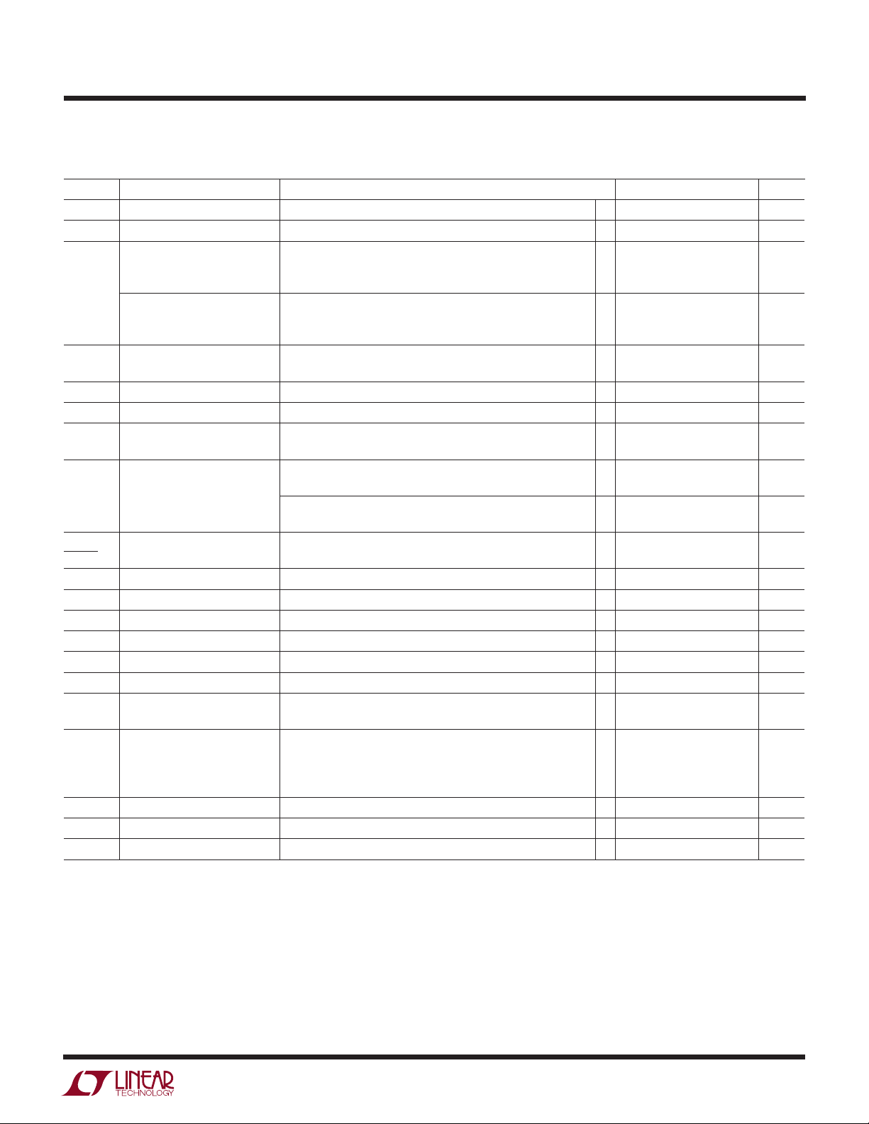
ELECTRICAL CHARACTERISTICS
The ● denotes the specifications which apply over the full operating temperature range, otherwise specifications are at TA = 25°C.
Total supply = (V
–
– VEE) = 2.5V to 36V (LT1787), 2.5V to 60V (LT1787HV) unless otherwise specified.
S
(Note 4)
SYMBOL PARAMETER CONDITIONS MIN TYP MAX UNITS
–
+
V
, V
S
V
SENSE
V
OS
Sense Amplifier Supply Voltage Single Supply Operation (LT1787) ● 2.5 36 V
S
Input Sense Voltage Full Scale V
Input Offset Voltage (S8) I
Input Offset Voltage (MS8) I
Single Supply Operation (LT1787HV)
+
= V
SENSE
= 0, VS Supply = 5V –75 ±40 75 µV
OUT
≤ 70°C ● –135 135 µV
0°C ≤ T
A
–40°C ≤ T
I
= 0 (LT1787) –100 100 µV
OUT
≤ 70°C ● –160 160 µV
0°C ≤ T
A
–40°C ≤ T
I
= 0 (LT1787HV) –100 100 µV
OUT
≤ 70°C ● –160 160 µV
0°C ≤ T
A
–40°C ≤ T
= 0, VS Supply = 5V –125 ±40 125 µV
OUT
≤ 70°C ● –230 230 µV
0°C ≤ T
A
–40°C ≤ T
I
= 0 (LT1787) –150 150 µV
OUT
0°C ≤ T
≤ 70°C ● –250 250 µV
A
–40°C ≤ T
I
= 0 (LT1787HV) –150 150 µV
OUT
≤ 70°C ● –250 250 µV
0°C ≤ T
A
–40°C ≤ T
–
– V
, VS = 10V, V
S
S
≤ 85°C ● –200 200 µV
A
≤ 85°C ● –225 225 µV
A
≤ 85°C ● –225 225 µV
A
≤ 85°C ● –250 250 µV
A
≤ 85°C ● –280 280 µV
A
≤ 85°C ● –280 280 µV
A
= 5V, AV = 8 ±10% ● 500 mV
BIAS
● 2.5 60 V
2
LT1787/LT1787HV
ELECTRICAL CHARACTERISTICS
The ● denotes the specifications which apply over the full operating temperature range, otherwise specifications are at TA = 25°C.
Total supply = (V
–
– VEE) = 2.5V to 36V (LT1787), 2.5V to 60V (LT1787HV) unless otherwise specified.
S
(Note 4)
SYMBOL PARAMETER CONDITIONS MIN TYP MAX UNITS
VOS TC Temperature Coefficient of VOSVS Supply = 5V (Note 5) 0.5 2 µV/°C
I
OUT(O)
V
OUT(O)
g
m
A
V
No-Load Output Current Error V
No-Load Output Voltage Error V
SENSE
SENSE
(S8) 0°C ≤ T
–40°C ≤ T
No-Load Output Voltage Error V
SENSE
(MS8) 0°C ≤ T
–40°C ≤ T
Tranconductance, I
Gain, V
OUT/VSENSE
OUT/VSENSE±VSENSE
V
Supply = Total Supply + |V
S
±V
SENSE
= 0V 4 nA
= 0V, VS Supply = 5V –600 600 µV
≤ 70°C ● –1080 1080 µV
A
≤ 85°C ● –1600 1600 µV
A
= 0V, VS Supply = 5V –1000 1000 µV
≤ 70°C ● –1840 1840 µV
A
≤ 85°C ● –2000 2000 µV
A
= 10mV, 50mV, 100mV, 150mV, 250mV, 400 µA/V
|
SENSE
= 100mV, VS Supply = 5V ● 7.6 8 8.4 V/V
Output Voltage Gain Error ● –5 2 5 %
VS PSRR VS Supply Rejection Ratio V
VEE PSRR Negative Supply Rejection Ratio V
∆V
∆V
I
S+(O)
I
S–(O)
I
EE(O)
I
OUT
V
OUT
OS
BIAS
Change in Input Offset Voltage V
with Change in V
Voltage V
BIAS
Positive Input Sense Current V
Negative Input Sense Current V
Negative Supply Current V
Output Current V
Output Voltage V
Ripple Rejection V
V
OMIN
Minimum Output Voltage V
Unipolar Output V
Saturation Voltage V
V
OMAX
R
G1A, RG2A
R
OUT
Maximum Output Voltage V
Input Gain-Setting Resistor Pin 1 to Pin 2, Pin 7 to Pin 8 1.25 kΩ
Output Resistor Pin 5 to Pin 6 20 kΩ
= 0V, VS Supply = 2.5V to 36V (LT1787) ● 120 135 dB
SENSE
= 0V, VS Supply = 2.5V to 60V (LT1787HV) ● 120 135 dB
V
SENSE
= 0V, VS Supply = 15V, V
SENSE
= –1V to –15V (LT1787)
V
EE
V
= 0V, VS Supply = 40V, V
SENSE
= –1V to –15V (LT1787HV)
V
EE
= 0V, VS Supply = 36V, V
SENSE
= 0V, VS Supply = 60V, V
SENSE
= 0V ● 10 20 µA
SENSE
= 0V ● 50 100 µA
SENSE
= 0V ● 60 120 µA
SENSE
= ±128mV ±50 µA
SENSE
SENSE
S
SENSE
V
SENSE
SENSE
SENSE
V
SENSE
V
SENSE
+
= V
= ±128mV, V
–
= 20V, ∆VS Supply = 1V, f = 1kHz ● 80 88 dB
S
= 0V, V
+
= V
– V
S
= 2mV, V
= 4mV, V
= 5mV, V
= 6mV, V
+
≥ 3.3V V
S
= 0V ● 30 45 mV
BIAS
–
= –128mV, V
S
= 0V ● 32 50 mV
BIAS
= 0V ● 38 55 mV
BIAS
= 0V ● 43 60 mV
BIAS
= 0V ● 49 65 mV
BIAS
= 0V, ● 100 130 dB
BIAS
= 0V, ● 100 130 dB
BIAS
= 0.5V to 25V (LT1787) ● 100 130 dB
BIAS
= 0.5V to 25V (LT1787HV) ● 100 130 dB
BIAS
±1.024 V
BIAS
= 0V 10 mV
BIAS
+
– 0.75 V
S
Note 1: Absolute Maximum Ratings are those values beyond which the life
of a device may be impaired.
Note 2: ESD (Electrostatic Discharge) sensitive devices. Extensive use of
ESD protection devices are used internal to the LT1787/LT1787HV,
however, high electrostatic discharge can damage or degrade the device.
Use proper ESD handling precautions.
Note 3: The LT1787C/LT1787HVC are guaranteed to meet specified
performance from 0°C to 70° and are designed, characterized and
expected to meet these extended temperature limits, but are not tested at
–40°C and 85°C. The LT1787I/LT1787HVI are guaranteed to meet the
extended temperature limits.
Note 4: Testing done at V
= 1.25V, VEE = 0V unless otherwise
BIAS
specified.
Note 5: This parameter is not 100% tested.
3

LT1787/LT1787HV
SENSE VOLTAGE (V
S
+
– V
S
–
) (mV)
–250
OUTPUT VOLTAGE (V)
2.5
2.0
1.5
1.0
0.5
V
BIAS
–0.5
–1.0
–1.5
–2.0
–2.5
150
1787 G06
–150
–50
50
250
VS = 5.5V TO 60V
V
BIAS
= 2.5V
V
EE
= 0V
W
U
TYPICAL PERFORMANCE CHARACTERISTICS
Input Offset Voltage vs
Supply Voltage
50
+
–
V
= V
S
V
BIAS
V
EE
S
= 0V
= –1.25V
40
30
20
10
0
–10
–20
–30
INPUT OFFSET VOLTAGE (µV)
–40
–50
0
10
20
TOTAL SUPPLY VOLTAGE (V)
Input Offset Voltage vs
Negative Supply Voltage
30
+
–
V
= V
= 2.5V
S
S
= 1V
V
BIAS
20
10
0
–10
INPUT OFFSET VOLTAGE (µV)
–20
–30
0
–5 –10 –15 –20 –25
NEGATIVE SUPPLY VOLTAGE (V)
T
T
T
A
T
= 25°C
A
T
= –40°C
A
A
= 85°C
A
= 25°C
= –40°C
30 40
T
A
= 85°C
No Load Output Voltage
vs Supply Voltage
400
+
–
V
= V
S
S
V
BIAS
V
EE
= 0V
= –1.25V
T
= 85°C
A
300
200
100
0
T
= 25°C
A
–100
OUTPUT VOLTAGE (µV)
–200
–300
50
60
–400
010
= –40°C
T
A
20 4030
50
60
TOTAL SUPPLY VOLTAGE (V)
1787 G01
1787 G02
Input Offset Voltage vs
Temperature
50
+
–
V
= V
S
V
BIAS
V
EE
S
= 0V
= –1.25V
40
30
No Load Output Current vs
Supply Voltage
10
T
= –40°C
A
8
6
T
= 25°C
A
4
2
0
–2
–4
OUTPUT CURRENT (nA)
–6
V
= 1V
BIAS
= 0V
V
EE
–8
+
= V
V
S
–10
S
0
10
= 85°C
T
A
–
30 40
20
TOTAL SUPPLY VOLTAGE (V)
Output Voltage vs Sense Voltage
(Bidirectional Mode)
50
60
1787 G03
20
10
0
–10
–20
INPUT OFFSET VOLTAGE (µV)
–30
–40
–30
1787 G04
–50
–20 0 20 40 60
–40
TEMPERATURE (°C)
80
1787 G05
85
1.4
1.2
1.0
0.8
0.6
OUPUT VOLTAGE (V)
0.4
0.2
4
Output Voltage vs Sense Voltage
(Unidirectional Mode)
VS = 2.5V TO 60V
T
= –40°C TO 85°C
A
= V
V
BIAS
EE
0
30 60 90 150
0
SENSE VOLTAGE (V
+
– V
S
S
120
–
) (mV)
1787 G07
8.195
8.185
8.175
8.165
GAIN (V/V)
8.155
8.145
8.135
V
= (2.5V + |V
S
–40
–20 0 20 40 60
TEMPERATURE (°C)
Gain vs FrequencyGain vs Temperature
|)TO 60V
SENSE
+
–
V
> V
S
S
+
–
V
< V
S
S
80
85
1787 G08
30
20
10
0
–10
GAIN (dB)
–20
–30
–40
–50
0.1k 1k
10k 1M100k
FREQUENCY (Hz)
V
SENSE
= 10mV
10M
1787 G09
100M

W
SENSE VOLTAGE (V
S
+
– V
S
–
) (mV)
–128
POSITIVE INPUT SENSE CURRENT (µA)
60
50
40
30
20
10
0
–64
0
32
1787 G17
–96 –32
64
96
128
VS = (2.5V + |V
SENSE
|) TO 60V
TA = 85°C
TA = –40°C
TA = 25°C
U
TYPICAL PERFORMANCE CHARACTERISTICS
LT1787/LT1787HV
Supply Current vs Supply Voltage
75
70
65
60
55
50
SUPPLY CURRENT (µA)
45
+
V
= V
S
40
0
10
TA = 85°C
TA = 25°C
T
= –40°C
A
–
S
20 30 40 50 60
TOTAL SUPPLY VOLTAGE (V)
Step Response at
V
= 0V to 10mV
SENSE
10mV
0V
80mV
0V
1787 G10
Negative Input Sense Current vs
Sense Voltage
120
110
100
90
80
70
60
50
40
NEGATIVE INPUT SENSE CURRENT (µA)
30
–128
–96 –32
VS = (2.5V + |V
–64
SENSE VOLTAGE (V
0
+
S
Step Response at
V
= 0V to 128mV
SENSE
100mV
0V
1V
500mV
0V
SENSE
32
– V
|) TO 60V
TA = 85°C
TA = 25°C
TA = –40°C
64
–
) (mV)
S
96
1787 G11
128
Positive Input Sense Current vs
Sense Voltage
Step Response at
V
= 0V to 128mV
SENSE
100mV
0V
1V
500mV
0V
= 0pF 1787 G12
C
OUT
Step Response at
V
SENSE
0V
–100mV
0V
–500mV
–1V
C
= 0 1787 G19
OUT
= 0V to –128mV
C
OUT
Step Response at
V
SENSE
0V
–100mV
0V
–500mV
–1V
C
OUT
= 0pF 1787 G18
= 0V to –128mV
= 1000pF 1787 G14
C
OUT
Step Response at
V
SENSE
100mV
0V
–100mV
1V
0V
–1V
C
OUT
= 1000pF 1787 G13
= –128mV to 128mV
= 0 1787 G20
5

LT1787/LT1787HV
W
U
TYPICAL PERFORMANCE CHARACTERISTICS
Step Response at
V
SENSE
100mV
–100mV
1V
0V
–1V
C
OUT
= 128mV to –128mV
= 2200pF 1787 G15
V
Error vs Supply Ripple
OUT
Voltage (V
1000
900
800
700
600
500
400
300
200
SUPPLY RIPPLE VOLTAGE (mV)
LESS THAN 0.1%
100
0
100 10k 100k 1M
V
OUT
ERROR
1k
SENSE
FREQUENCY (Hz)
UUU
PIN FUNCTIONS
FIL–, FIL+ (Pins 1, 8): Negative and Positive Filter Terminals. Differential mode noise can be filtered by connecting
a capacitor across FIL– and FIL+. Pole frequency
f
= 1/(2πRC), R = 1.25kΩ.
–3dB
–
V
(Pin 2): Negative Input Sense Terminal. Negative
S
sense voltage will result in an output sinking current
proportional to the sense current. V
internal gain-setting resistor R
rent to the internal amplifier.
DNC (Pin 3): Do Not Connect. Connected internally. Do not
connect external circuitry to this pin.
V
(Pin 4): Negative Supply or Ground for Single Supply
EE
Operation.
–
is connected to an
S
and supplies bias cur-
G1A
= ±128mV)
0.5%
V
5%
1%
2%
1787 G16
(Pin 6): Output Bias Pin. For single supply, bidirec-
BIAS
tional current sensing operation, V
external bias voltage, so that at V
V
OUT(O)
+ V
. For dual supply, bidirectional current
BIAS
sensing operation, V
V
= V
OUT
+
V
(Pin 7): Positive Input Sense Terminal. Positive sense
S
OUT(O)
at V
Output Voltage vs Sense Voltage
16
–
V
= 18V
14
S
= 0V
V
BIAS
12
V
= –18V
EE
10
8
6
4
2
0
OUTPUT VOLTAGE (V)
–2
–4
–6
–8
–0.8 –0.4
SENSE VOLTAGE (V
is connected to ground. Thus,
BIAS
= 0V.
SENSE
0.4
0 0.8 2.0
BIAS
SENSE
+
– V
S
is connected to an
= 0V, V
1.2 1.6
–
) (V)
S
OUT
1787 G21
voltage will result in an output sourcing current proportional to the sense current. V
gain-setting resistor R
a load to V
–
will allow the LT1787 to measure its own
S
G2A
+
is connected to an internal
S
. Connecting a supply to V
+
and
S
supply current.
=
V
(Pin 5): Voltage Output or Current Output propor-
OUT
tional to the magnitude of the sense current flowing
through R
tion, V
OUT
. For bidirectional current sensing opera-
SENSE
= AV • V
SENSE
+ V
OUT(O)
+ V
BIAS
,
where:
+
V
V
V
OUT(O)
OUT
OUT
> V
< V
BIAS
BIAS
for V
for V
S
S
is the no load output voltage at V
> V
+
< V
–
S
–
S
= 0V.
SENSE
6

BLOCK DIAGRAM
W
LT1787/LT1787HV
R
–
V
S
SENSE
I
SENSE
+
V
S
R
G1A
1.25k
R
G1B
1.25k
–
Q1
CURRENT MIRROR
A1
U
–
FIL
V
EE
WUU
Figure 1. LT1787 Functional Diagram
APPLICATIONS INFORMATION
The LT1787 high side current sense amplifier (Figure 1)
provides accurate bidirectional monitoring of current
through a user-selected sense resistor. The sense voltage
is amplified by a fixed gain of 8 and level shifted from the
positive power supply to the ground referenced outputs.
The output signal may be used in a variety of ways to
interface with subsequent signal processing circuitry.
Input and output filtering are easily implemented to eliminate aliasing errors.
Theory of Operation
Inputs V
+
and V
S
resistors RG1 and RG2. The opposite ends of resistors R
and RG2 are forced to be at equal potentials by the voltage
gain of amplifier A1. The currents through RG1 and RG2 are
forced to flow through transistors Q1 and Q2 and are
summed at node V
current from RG1 and RG2 flowing through resistor R
gives a voltage gain of eight. Positive sense voltages result
in V
Pins VEE, V
being positive with respect to pin V
OUT
BIAS
ways to interface with subsequent circuitry. Split supply
–
apply the sense voltage to matched
S
by the 1:1 current mirror. The net
OUT
BIAS
and V
may be connected in a variety of
OUT
G1
OUT
.
R
G2A
1.25k
R
G2B
1.25k
+
I
OUT
R
OUT
Q2
20k
1787 F 01
+
FIL
V
BIAS
V
OUT
and single supply output configurations are shown in the
following sections.
Supply current for amplifier A1 is drawn from the V
S
–
pin.
The user may choose to include this current in the monitored current through R
by careful choice of connec-
SENSE
tion polarity.
Selection of External Current Sense Resistor
External R
resistor selection is a delicate trade-off
SENSE
between power dissipation in the resistor and current
measurement accuracy. The LT1787 makes this decision
less difficult than with competitors’ products. The maximum sense voltage may be as large as ±500mV to get
maximum resolution, however, high current applications
will not want to suffer this much power dissipation in the
sense resistor. The LT1787’s input offset voltage of 40µV
gives high resolution for low sense voltages. This wide
operating dynamic range gives the user wide latitude in
tailoring the range and resolution of his supply monitoring
function.
7

LT1787/LT1787HV
U
WUU
APPLICATIONS INFORMATION
Kelvin connection of the LT1787’s V
+
and V
S
the sense resistor should be used in all but the lowest
power applications. Solder connections and PC board
interconnect resistance (approximately 0.5mΩ per square)
can be a large error in high current systems. A 5-Amp
application might choose a 20mΩ sense resistor to give a
100mV full-scale input to the LT1787. Input offset voltage
will limit resolution to 2mA. Neglecting contact resistance
at solder joints, even one square of PC board copper at
each resistor end will cause an error of 5%. This error will
grow proportionately higher as monitored current levels
rise to tens or hundreds of amperes.
Input Noise Filtering
The LT1787 provides input signal filtering pins FIL+ and
FIL– that are internally connected to the midpoint taps of
resistors RG1 and RG2. These pins may be used to filter the
input signal entering the LT1787’s internal amplifier, and
should be used when fast current ripple or transients may
flow through the sense resistor. High frequency signals
above the 300kHz bandwidth of the LT1787’s internal
amplifier will cause errors. A capacitor connected between
FIL+ and FIL– creates a single pole low pass filter with
corner frequency:
f
= 1/(2πRC)
–3dB
where R = 1.25k. A 0.01µF capacitor creates a pole at
12.7kHz, a good choice for many applications.
Common mode filtering from the FIL+ and FIL– pins should
not be attempted, as mismatch in the capacitors from FIL
and FIL– will create AC common mode errors. Common
mode filtering must be done at the power supply output.
Output Signal Range
The LT1787’s output signal is developed by summing the
net currents through RG1 and RG2 into output resistor
R
. The pins V
OUT
OUT
and V
may be connected in
BIAS
numerous configurations to interface with following circuitry in either single supply or split supply applications.
Care must be used in connecting the output pins to
preserve signal accuracy. Limitations on the signal swing
–
inputs to
S
+
at V
input voltage V
saturation with loss of accuracy occurs for V
with absolute minimum swing at 30mV above VEE. V
may swing positive to within 0.75V of V
are imposed by the negative supply, VEE, and the
OUT
+
. In the negative direction, internal circuit
S
< 70mV
OUT
+
or a maximum
S
OUT
of 35V, a limit set by internal junction breakdown. Within
these contraints, an amplified, level shifted representation
of the R
voltage is developed across R
SENSE
OUT
.
Split Supply Bipolar Output Swing
Figure 2 shows the LT1787 used with split power supplies.
The V
signal appears at the V
pin is connected to ground, and the output
BIAS
pin. Bidirectional input currents
OUT
can be monitored with the output swinging positive for
current flow from V
+
and V
S
opposite direction cause V
–
. Input currents in the
S
to swing below ground.
OUT
Figure 2 shows an optional output capacitor connected
from V
to ground. This capacitor may be used to filter
OUT
the output signal before it is processed by other
circuitry.Figure 3 shows the voltage transfer function of
the LT1787 used in this configuration.
Single Supply with Shifted V
BIAS
Figure 4 shows the LT1787 used in a single supply mode
with the V
LT1634 voltage reference. The V
swing above and below V
pin shifted positive using an external
BIAS
output signal can
OUT
to allow monitoring of
BIAS
positive or negative currents through the sense resistor,
as shown in Figure 5. The choice of reference voltage is not
critical except for the precaution that adequate headroom
must be provided for V
to swing without saturating the
OUT
internal circuitry. The component values shown in Figure 4
allow operation with VS supplies as low as 3.1V.
Operation with A/D Converter
Figure 6 shows the LT1787 operating with the LTC1286
A/D converter. This low cost circuit is capable of 12-bit
resolution of unipolar currents. The –IN pin of the A/D
converter is biased at 1V by the resistor divider R1 and R2.
This voltage increases as sense current increases, with the
8

LT1787/LT1787HV
R2
5k
5%
1787 F06
I
OUT
C1
1µF
5V
V
REF
V
CC
GND
LTC1286
CS
CLK
D
OUT
+IN
–IN
TO µP
R
SENSE
5V
1
2
3
4
8
7
6
5
LT1787
FIL
+
FIL
–
V
BIAS
V
OUT
V
S
–
V
S
+
DNC
V
EE
R1
20k
5%
R
OUT
U
WUU
APPLICATIONS INFORMATION
CHARGER/
–5V
*OPTIONAL
LOAD
TO
1
2
3
4
C2
1µF
Figure 2. Split Supply Operation
1.5
VS = 3.3V TO 60V
T
1.0
0.5
0
R
SENSE
–
FIL
LT1787
–
V
S
DNC
V
EE
= –40°C TO 85°C
A
C1
8
+
FIL
+
V
S
7
V
BIAS
6
R
OUT
5
V
OUT
C3*
1000pF
1µF
OUTPUT
1787 F02
15V
CHARGER/
LOAD
TO
*OPTIONAL OUTPUT
R
SENSE
C1
C3*
1000pF
1µF
1µF
C2
1
–
FIL
LT1787HV
–
V
S
2
3
DNC
4
V
EE
8
+
FIL
+
V
S
7
V
6
BIAS
R
OUT
5
V
OUT
Figure 4. Charge/Discharge Current Monitor on
Single Supply with V
1.5
VS = 3.3V TO 60V
= –40°C TO 85°C
T
A
1.0
0.5
0
BIAS
= 1.25V
3.3V
TO
60V
3.3V
20k
5%
LT1634-1.25
1787 F04
–0.5
OUTPUT VOLTAGE (V)
–1.0
–1.5
–128
–96 –32
–64
SENSE VOLTAGE (V
0
32
+
– V
S
–
S
64
) (mV)
96
128
1787 F03
Figure 3. Split Supply Output Voltage
amplified sense voltage appearing between the A/D converters –IN and +IN terminals. The front page of the data
sheet shows a similar circuit which uses a voltage reference for improved accuracy and signal range. The LTC1286
converter uses sequential sampling of its –IN and +IN
inputs. Accuracy is degraded if the inputs move between
sampling intervals. A filter capacitor from FIL+ to FIL– as
well as a filter capacitor from V
BIAS
to V
may be
OUT
necessary if the sensed current changes more than 1LSB
within a conversion cycle.
–0.5
–1.0
OUTPUT VOLTAGE – OUTPUT BIAS VOLTAGE (V)
–1.5
–128
–96 –32
SENSE VOLTAGE (V
–64
0
32
+
– V
S
–
S
64
) (mV)
96
128
1787 F05
Figure 5. Single Supply Output Voltage
with V
Figure 6. Unidirectional Output into A/D
with Fixed Supply at V
BIAS
= 1.25V
+
S
9

LT1787/LT1787HV
U
WUU
APPLICATIONS INFORMATION
Buffered Output Operation
Figure 7 shows the LT1787’s outputs buffered by an
operational amplifier configured as an I/V converter. This
configuration is ideal for monitoring very low voltage
supplies. The LT1787’s V
reference voltage appearing at the op amp’s noninverting
input. This allows monitoring VS supplies as low as 2.5V.
The op amp’s output may swing from ground to its
positive supply voltage. The low impedance output of the
op amp may drive following circuitry more effectively than
the high output impedance of the LT1787. The I/V converter configuration also works well with split supply
voltages.
Single Supply Unidirectional Operation
Figure 8 shows the simplest connection in which the
LT1787 may be used. The V
ground, and the V
pin swings positive with increasing
OUT
sense current. The LT1787’s outputs can swing as low as
30mV as shown in Figure 9. Accuracy is sacrificed at small
pin is held equal to the
OUT
pin is connected to
BIAS
output levels, but this is not a limitation in protection
circuit applications or where sensed currents do not vary
greatly. Increased low level accuracy can be obtained by
level shifting V
above ground. The level shifting may
BIAS
be done with resistor dividers, voltage references or a
simple diode. Accuracy is ensured if the output signal is
sensed differentially between V
R
FIL
V
DNC
V
S
EE
0.1µF
–
LT1787HV
–
SENSE
C
TO
LOAD
1
2
3
4
Figure 8. Unidirectional Current Sensing Mode
V
R
V
BIAS
FIL
V
S
BIAS
OUT
OUT
1787 F08
+
+
and V
8
7
6
5
V
OUT
OUT
2.5V TO
60V
.
I
TO
CHARGER/
LOAD
R
SENSE
1
–
FIL
LT1787
–
V
S
2
3
DNC
4
V
EE
2.5V
SENSE
C1
8
+
FIL
+
V
S
7
V
BIAS
6
R
OUT
5
V
OUT
1M
5%
1µF
C3
1000pF
LT1389-1.25
Figure 7. Single Supply 2.5V Bidirectional Operation
with External Voltage Reference and I/V Converter
+
2.5V
–
A1
2.5V + V
LT1495
1787 F07
SENSE(MAX)
V
OUT A
0.30
0.25
0.20
0.15
0.10
OUTPUT VOLTAGE (V)
0.05
0
IDEAL
0
0.005
0.010
0.015 0.020
+
V
– V
S
–
S
0.025 0.030
(V)
1787 F09
Figure 9. Expanded Scale of Unidirectional Output
10

LT1787/LT1787HV
(
U
WUU
APPLICATIONS INFORMATION
Adjusting Gain Setting
The LT1787 may be used in all operating modes with an
external resistor used in place of the internal 20k R
resistor. When an external resistor is used, leave the V
pin floating or connected to the V
the internal R
from the circuit.
OUT
The voltage gain will be gm • R
pin. This will remove
OUT
where gm is the
OUT
OUT
BIAS
LT1787’s transconductance, 400µA/V typical. A nominal
gain of 40 may be obtained with an external 100k resistor
used in place of the internal 20k R
AV = gm • R
= 400µA/V • 100k = 40
OUT
OUT
:
U
PACKAGE DESCRIPTION
0.007
(0.18)
0.021
± 0.006
(0.53 ± 0.015)
* DIMENSION DOES NOT INCLUDE MOLD FLASH, PROTRUSIONS OR GATE BURRS. MOLD FLASH,
PROTRUSIONS OR GATE BURRS SHALL NOT EXCEED 0.006" (0.152mm) PER SIDE
** DIMENSION DOES NOT INCLUDE INTERLEAD FLASH OR PROTRUSIONS.
INTERLEAD FLASH OR PROTRUSIONS SHALL NOT EXCEED 0.006"
° – 6° TYP
0
Dimensions in inches (millimeters) unless otherwise noted.
MS8 Package
8-Lead Plastic MSOP
(LTC DWG # 05-08-1660)
0.040
± 0.006
(1.02 ± 0.15)
SEATING
PLANE
0.012
(0.30)
0.0256
REF
(0.65)
BSC
0.152mm) PER SIDE
The transconductance gm is set by on-chip resistors on
the LT1787. These resistors match well but have loose
absolute tolerance. This will normally require that the
external gain setting resistor be trimmed for initial accuracy. After trimming, the temperature stability of the gm
and therefore gain will be –200ppm/°C.
The only limitations placed upon the resistor choice is care
must be taken not to saturate the internal circuitry by
violating the V
0.034 ± 0.004
(0.86 ± 0.102)
0.006 ± 0.004
(0.15 ± 0.102)
specification of VS + –0.75V.
OMAX
0.118 ± 0.004*
(3.00 ± 0.102)
0.193 ± 0.006
(4.90 ± 0.15)
8
7
12
6
3
5
0.118 ± 0.004**
(3.00 ± 0.102)
MSOP (MS8) 1098
4
0.010 – 0.020
(0.254 – 0.508)
0.008 – 0.010
(0.203 – 0.254)
*
DIMENSION DOES NOT INCLUDE MOLD FLASH. MOLD FLASH
SHALL NOT EXCEED 0.006" (0.152mm) PER SIDE
**
DIMENSION DOES NOT INCLUDE INTERLEAD FLASH. INTERLEAD
FLASH SHALL NOT EXCEED 0.010" (0.254mm) PER SIDE
× 45°
0.016 – 0.050
(0.406 – 1.270)
0.053 – 0.069
(1.346 – 1.752)
0°– 8° TYP
0.014 – 0.019
(0.355 – 0.483)
Information furnished by Linear Technology Corporation is believed to be accurate and reliable.
However, no responsibility is assumed for its use. Linear Technology Corporation makes no representation that the interconnection of its circuits as described herein will not infringe on existing patent rights.
S8 Package
8-Lead Plastic Small Outline (Narrow 0.150)
(LTC DWG # 05-08-1610)
0.004 – 0.010
(0.101 – 0.254)
0.228 – 0.244
(5.791 – 6.197)
TYP
0.050
(1.270)
BSC
0.189 – 0.197*
(4.801 – 5.004)
7
8
1
2
5
6
0.150 – 0.157**
(3.810 – 3.988)
3
4
SO8 1298
11

LT1787/LT1787HV
TYPICAL APPLICATION
Split or Single Supply Operation, Bidirectional Output into A/D
IS = ±125mA
SRCE
V
–5V
1
–
FIL
–
V
S
2
3
DNC
4
EE
V
EE
V
≈4.75V
U
1Ω
1%
LT1787
V
20k
V
FIL
V
BIAS
OUT
8
+
+
S
7
6
5
(±1V)
V
OUT
OPTIONAL SINGLE
SUPPLY OPERATION:
DISCONNECT V
AND CONNECT IT TO V
FROM GROUND
REPLACE –5V SUPPLY
WITH GROUND.
OUTPUT CODE FOR ZERO
CURRENT WILL BE ~2430
BIAS
REF
V
CC
5V
10µF
16V
1
7
LTC1404
4
V
EE
–5V
8
CONV
CLK
DOUT
6
5
10µF
16V
CLOCKING
CIRCUITRY
D
OUT
1787 TA02
2
A
IN
3
V
REF
GND
10µF
16V
.
RELATED PARTS
PART NUMBER DESCRIPTION COMMENTS
LTC1043 Dual Precision Instrumentation Switched Capacitor Building Block 120dB CMRR, 3V to 18V Operation
LT1490/LT1491 Dual and Quad Micropower Rail-to-Rail Input and Output Op Amps 50µA Amplifier, 2.7V to 40V Operation,
Over-The-Top
LT1620/LT1621 Rail-to-Rail Current Sense Amplifiers Accurate Output Current Programming, Battery
Charging to 32V
Over-The-Top is a trademark of Linear Technology Corporation.
TM
Inputs
12
Linear Technology Corporation
1630 McCarthy Blvd., Milpitas, CA 95035-7417
(408) 432-1900 ● FAX: (408) 434-0507
●
www.linear-tech.com
1787f LT/TP 0100 4K • PRINTED IN USA
LINEAR TECHNOLOGY CORPORATION 1999
 Loading...