

Linear Technology LT1786F Datasheet
LT1786F
SMBus Programmable
CCFL Switching Regulator
FEATURES
■
Wide Battery Input Range: 4.5V to 30V
■
Grounded Lamp or Floating Lamp Configurations
■
Open Lamp Protection
■
Precision 100µA Full-Scale DAC
Programming Current
■
2-Wire SMBus Interface
■
Two Selectable SMBus Addresses
■
DAC Setting Is Retained in Shutdown
U
APPLICATIONS
■
Notebook and Palmtop Computers
■
Portable Instruments
■
Personal Digital Assistants
U
DESCRIPTION
The LT®1786F is a fixed frequency, current mode, switching regulator that provides the control function for Cold
Cathode Fluorescent Lighting (CCFL). The IC includes an
efficient high current switch, an oscillator, output drive
logic, control circuitry and a micropower 6-bit 100µ A fullscale current output DAC. The DAC provides simple “bits-
to-lamp-current control” and communicates using the
2-wire SMBus serial interface. The LT1786F acts as an
SMBus slave device using one of two selectable SMBus
addresses set by the address pin ADR.
On Power-up, the DAC output current assumes midrange
or zero scale, depending on the logic state of the ADR
pin.The entire IC can be shut down through the SMBSUS
pin or by setting the SHDN bit = 1 in the SMBus command
byte. Digital data for the DAC output current is retained
internally and the supply current drops to 40µ A for standby
operation. The active low SHDN pin disables the CCFL
control circuitry, but keeps the DAC alive. Supply current
in this operating mode drops to 150µA.
The LT1786F control circuitry operates from a logic supply
voltage of 3.3V or 5V. The IC also has a battery supply pin
that operates from 4.5V to 30V. The LT1786F draws 6mA
typical quiescent current. A 200kHz switching frequency
minimizes magnetic component size. Current mode switching techniques with cycle-by-cycle limiting gives high
reliability and simple loop frequency compensation. The
LT1786F is available in a 16-pin narrow SO package.
, LTC and LT are registered trademarks of Linear Technology Corporation.
TYPICAL APPLICATION
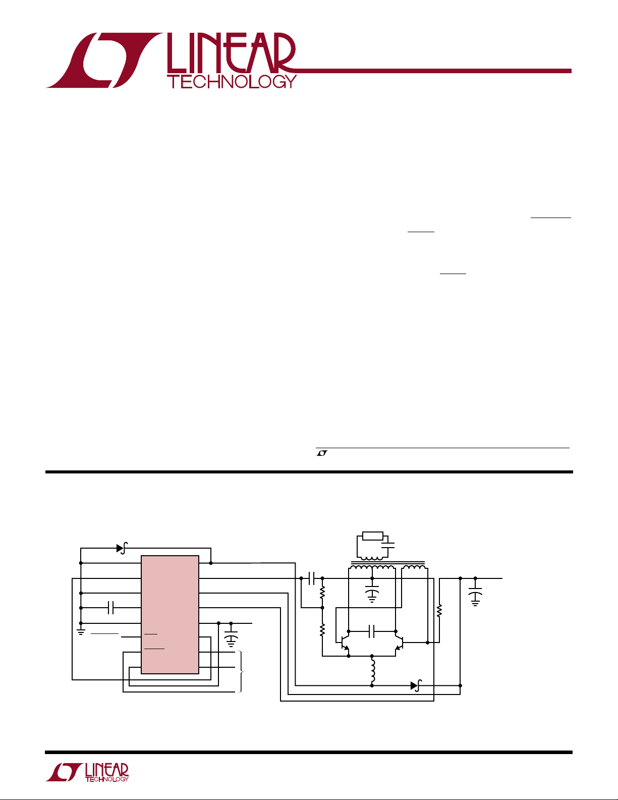
90% Efficient Floating CCFL with 2-Wire SMBus Control of Lamp Current
D1
BAT85
1
CCFL
PGND
2
I
CCFL
3
C7, 1µF
SHUTDOWN
ALUMINUM ELECTROLYTIC IS RECOMMENDED FOR C3A AND C3B.
MAKE 3CB ESR ≥ 0.5Ω TO PREVENT DAMAGE TO THE LT1786F HIGH-SIDE
SENSE RESISTOR DUE TO SURGE CURRENTS AT TURN-ON
C1 MUST BE A LOW LOSS CAPACITOR, C1 = WIMA MKI OR MKP-20
= PANASONIC ECH-U
Q1, Q2 = ZETEX ZTX849 OR ROHM 2SC5001
4
5
6
7
8
DIO
CCFL V
AGND
SHDN
SMBSUS
ADR
LT1786F
C
CCFL V
ROYER
BULB
BAT
V
I
OUT
SCL
SDA
16
SW
15
14
13
12
CC
11
10
9
U
CCFL BACKLIGHT APPLICATION CIRCUITS
CONTAINED IN THIS DATA SHEET ARE COVERED
BY U.S. PATENT NUMBER 5408162
AND OTHER PATENTS PENDING
3V ≤ V
CC
≤ 6.5V
+
C4
2.2µF
TO
SMBus
HOST
0µA TO 50µA I
0mA TO 6mA LAMP CURRENT
FOR A TYPICAL DISPLAY.
C5
1000pF
R3
100k
CCFL
LAMP
10
321 5
R2
220k
CURRENT GIVES
+
C1*
0.068µF
Q2* Q1*
L1 = COILTRONICS CTX210605
L2 = COILTRONICS CTX100-4
*DO NOT SUBSTITUTE COMPONENTS
COILTRONICS (561) 241-7876
L1
+
C3A
2.2µF
R1
750Ω
35V
BAT
8V TO 28V
6
C3B
2.2µF
35V
C2
27pF
3kV
4
L2
100µH
FOR ADDITIONAL CCFL/LCD CONTRAST APPLICATION CIRCUITS,
REFER TO THE LT1182/83/84/84F DATA SHEET
D1
1N5818
1786F TA01
1
LT1786F
WW
W
U
ABSOLUTE MAXIMUM RATINGS
VCC........................................................................... 7V
BAT, Royer, BULB .................................................. 30V
CCFL VSW............................................................... 60V
Shutdown ................................................................. 6V
I
Input Current .............................................. 10mA
CCFL
DIO Input Current (Peak, <100ms).................... 100mA
Digital Inputs .............................. –0.3V to (VCC + 0.3V)
Digital Outputs............................ –0.3V to (VCC + 0.3V)
DAC Output Voltage ..................... –15V to (VCC + 0.3V)
Junction Temperature (Note 1)............................ 100°C
Operating Ambient Temperature Range ..... 0°C to 70°C
Storage Temperature Range ................ –65°C to 150°C
Lead Temperature (Soldering, 10 sec)................. 300°C
U
PACKAGE/ORDER INFORMATION
TOP VIEW
16
CCFL V
SW
15
BULB
14
BAT
13
ROYER
12
V
CC
11
I
OUT
10
SCL
9
SDA
I
CCFL
CCFL V
AGND
SHDN
ADR
1
2
3
DIO
4
C
5
6
7
8
S PACKAGE
16-LEAD PLASTIC SO
T
= 100°C, θJA = 100°C/W
JMAX
CCFL PGND
SMBSUS
Consult factory for Industrial and Military grade parts.
W
ORDER PART
NUMBER
LT1786FCS
ELECTRICAL CHARACTERISTICS
TA = 25°C, VCC = SHUTDOWN = SMBSUS = SCL = SDA = 3.3V, BAT = Royer = BULB = 12V, I
DIO = I
SYMBOL PARAMETER CONDITIONS MIN TYP MAX UNITS
I
Q
ISUS SMBSUS Supply Current SMBSUS = 0V or Command Code Bit 7 = 1, ● 40 100 µA
I
SHDN
f Switching Frequency Measured at CCFL VSW, ISW = 50mA, 175 200 225 kHz
DC(MAX) Maximum Switch Duty Cycle Measured at CCFL V
BV Switch Breakdown Voltage Measured at CCFL V
= GND, CCFL VC = 0.5V, unless otherwise specified.
OUT
Supply Current 3V ≤ VCC ≤ 6.5V, I
CCFL VC = Open (Note 2)
SHUTDOWN Supply Current SHUTDOWN = 0V, CCFL VC = Open (Note 2) ● 150 300 µA
SHUTDOWN Input Bias Current SHUTDOWN = 0V, CCFL VC = Open 5 10 µA
SHUTDOWN Threshold Voltage ● 0.45 0.85 1.2 V
I
= 100µA, CCFL VC = Open ● 160 200 240 kHz
CCFL
Switch Leakage Current VSW = 12V, Measured at CCFL V
VSW = 30V, Measured at CCFL V
I
Summing Voltage 3V ≤ VCC ≤ 6.5V 0.425 0.465 0.505 V
CCFL
∆I
Summing Voltage for I
CCFL
∆Input Programming Current
CCFL VC Offset Sink Current CCFL VC = 1.5V, Positive Current Measured into Pin –5 5 15 µA
∆CCFL VC Source Current for I
∆I
Programming Current CCFL VC = 1.5V
CCFL
CCFL VC to DIO Current Servo Ratio DIO = 5mA out of Pin, Measure I(VC) at CCFL VC = 1.5V ● 94 99 104 µA/mA
CCFL VC Low Clamp Voltage V
CCFL VC High Clamp Voltage I
CCFL VC Switching Threshold CCFL VSW DC = 0% ● 0.6 0.95 1.3 V
CCFL High-Side Sense Servo Current I
= 0µA to 100µA 5 15 mV
CCFL
= 25µA, 50µA, 75µA, 100µA, ● 4.70 4.95 5.20 µA/µA
CCFL
– V
BAT
BULB
= 100µA ● 1.7 2.1 2.4 V
CCFL
= 100µA, I(VC) = 0µA at CCFL VC = 1.5V ● 0.93 1.00 1.07 A
CCFL
= 0µA ● 6 9.5 mA
OUT
SW
SW
SW
SW
= BULB Protect Servo Voltage ● 0.1 0.3 V
= CCFL VSW = Open,
CCFL
80 85 %
● 75 85 %
60 70 V
● 0.385 0.465 0.555 V
20 µA
40 µA
U
2
LT1786F
ELECTRICAL CHARACTERISTICS
TA = 25°C, VCC = SHUTDOWN = SMBSUS = SCL = SDA = 3.3V, BAT = Royer = BULB = 12V, I
DIO = I
SYMBOL PARAMETER CONDITIONS MIN TYP MAX UNIT
I
LIM
V
SAT
∆I
∆I
SW
I
IN
V
IH
V
IL
V
OL
SMBus Timing (Notes 4, 5)
f
SMB
t
BUF
t
HD:STA
t
SU:STA
t
SU:STO
t
HD:DAT
t
SU:DAT
t
LOW
t
HIGH
t
f
t
r
= GND, CCFL VC = 0.5V, unless otherwise specified.
OUT
CCFL High-Side Sense Servo Current BAT = 5V to 30V, I
Line Regulation I(V
CCFL High-Side Sense Supply Current Current Measured into BAT and Royer Pins ● 50 100 150 µA
BULB Protect Servo Voltage I
CCFL
Servo Voltage Measured between BAT and BULB Pins
BULB Input Bias Current I
CCFL
CCFL Switch Current Limit Duty Cycle = 50% ● 1.25 1.9 3.0 A
Duty Cycle = 75% (Note 3)
CCFL Switch On Resistance CCFL ISW = 1A ● 0.6 1.0 Ω
Q
Supply Current Increase During CCFL ISW = 1A 20 30 mA/A
CCFL Switch On Time
DAC Resolution 6 Bits
DAC Full-Scale Current V(I
DAC Zero Scale Current V(I
DAC Differential Nonlinearity ● ±0.1 ±1 LSB
DAC Supply Voltage Rejection 3V ≤ VCC ≤ 6.5V, I
Logic Input Current 0V ≤ VIN ≤ V
High Level Input Voltage ADR ● VCC – 0.3 V
SMBSUS
SCL, SDA
Low Level Input Voltage SMBSUS, ADR ● 0.8 V
SCL, SDA ● 0.6 V
Low Level Output Voltage I
OUT
I
OUT
SMB Operating Frequency ● 10 100 kHz
Bus Free Time Between Stop and Start Condition ● 4.7 µs
Hold Time After (Repeated) Start Condition ● 4.0 µs
Repeated Start Condition Setup Time ● 4.7 µs
Stop Condition Setup Time ● 4.0 µs
Data Hold Time ● 300 ns
Data Setup Time ● 250 ns
Clock Low Period ● 4.7 µs
Clock High Period ● 4.0 50 µs
Clock/Data Fall Time ● 300 ns
Clock/Data Rise Time ● 1000 ns
= 100µA, 0.1 0.16 %/V
) = 0µA at CCFL VC = 1.5V
C
CCFL
= 100µA, I(VC) = 0µA at CCFL VC = 1.5V, ● 6.5 7.0 7.5 V
= 100µA, I(VC) = 0µA at CCFL VC = 1.5V 5 9 µA
) = 0.465V 98 100 102 µA
OUT
) = 0.465V ● ±200 nA
OUT
CC
= Full Scale, V(I
OUT
) = 0.465V ● 0.2 2 LSB
OUT
= 3mA, SDA Only ● 0.4 V
= 1.6mA, SMBSUS = 0V, Measured at SHDN Pin ● 0.4 V
= CCFL VSW = Open,
CCFL
● 0.9 1.6 2.6 A
● 96 100 104 µA
● ±1 µA
● 2.4 V
● 1.4 V
The ● denotes specifications which apply over the specified operating
temperature range.
Note 1: T
is calculated from the ambient temperature TA and power
J
dissipation PD according to the following formula:
LT1786FCS: T
= TA + (PD)(100°C/W)
J
Note 2: Does not include switch leakage.
Note 3: For duty cycles (DC) between 50% and 80%, minimum
guaranteed switch current is given by I
= 1.4(1.393 – DC) for the
LIM
LT1786F due to internal slope compensation circuitry.
Note 4: Timings for all signals are referenced to V
and VIL signals.
IH
Note 5: These parameters are guaranteed by design and are not tested in
production. Refer to the Timing Diagrams for additional information.
3
LT1786F
I
CCFL
PROGRAMMING CURRENT (µA)
5
4
3
2
1
0
–1
–2
–3
–4
–5
–6
–7
–8
–9
–10
40 80 120 160
1786 G09
20020060 100 140 180
T = –55°C
T = 25°C
T = 125°C
∆I
CCFL
SUMMING VOLTAGE (mV)
TEMPERATURE (°C)
–75
CCFL FREQUENCY (kHz)
220
240
125
1786 G06
200
180
160
–25
25
75
175
210
230
190
170
100
–50
0
50
150
W
U
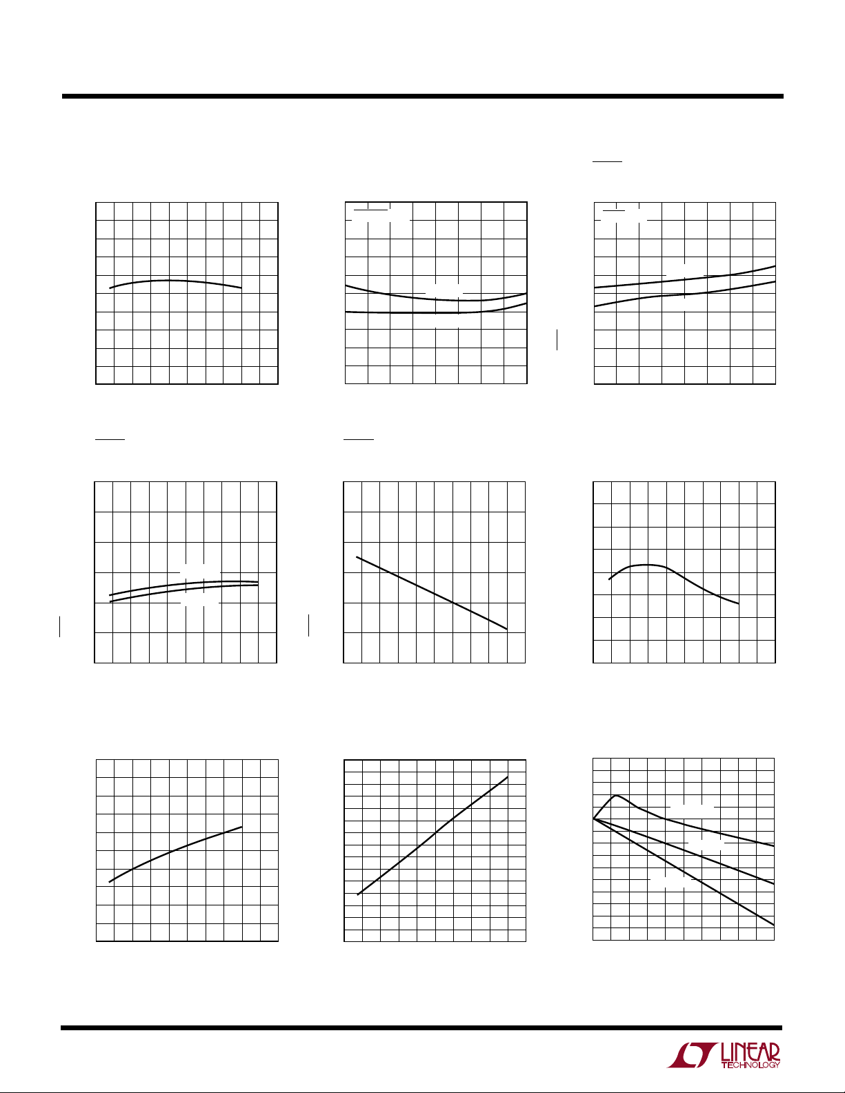
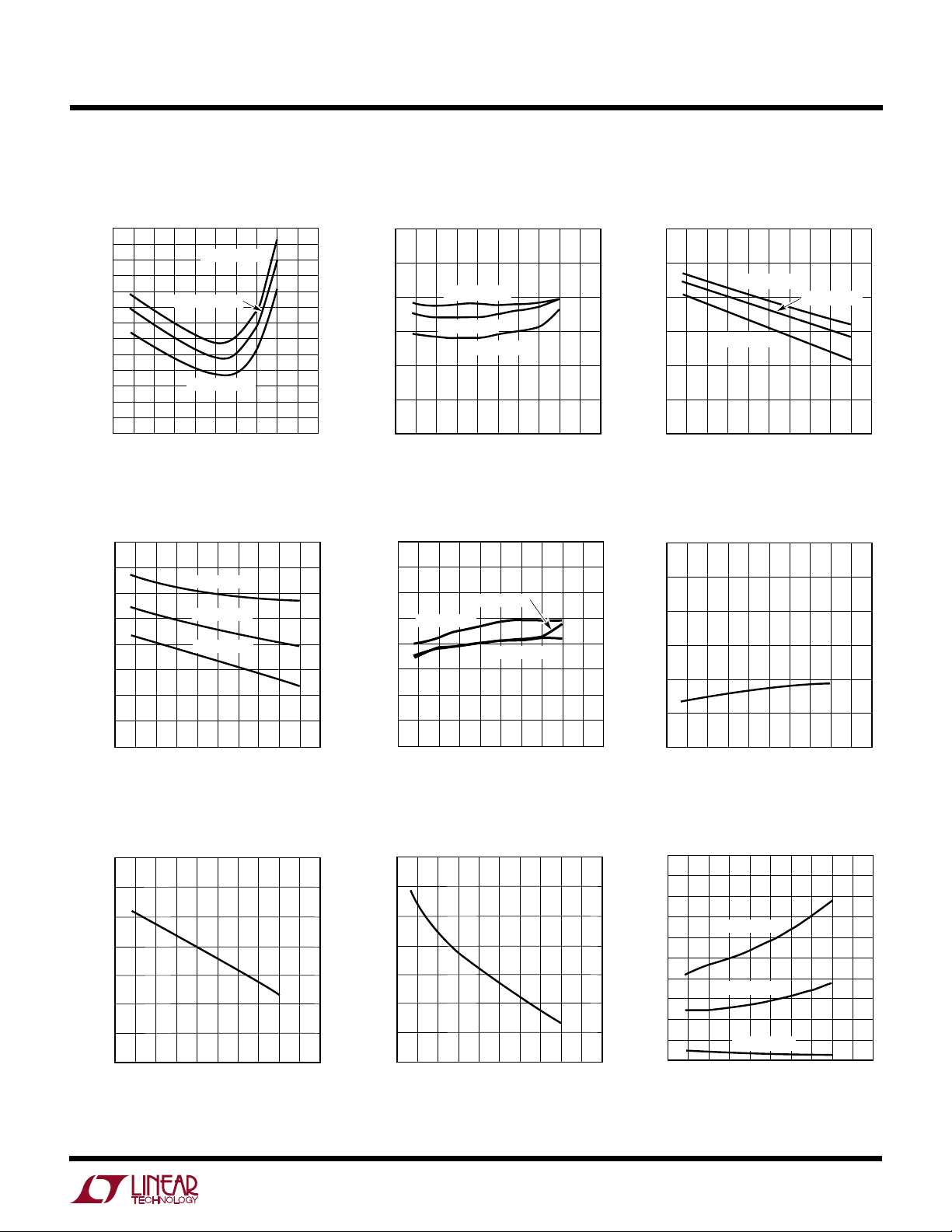
TYPICAL PERFORMANCE CHARACTERISTICS
Supply Current
vs Temperature
10
9
8
7
6
5
4
3
SUPPLY CURRENT (mA)
2
1
0
–25–50 0 50 100 150
–75
25
TEMPERATURE (°C)
SHDN Input Bias Current
vs Temperature
6
5
4
3
75
VCC = 5V
125
1786 G01
175
ISUS Current vs Temperature
100
SMBSUS = 0V
90
8O
70
60
50
ISUS (µA)
40
30
20
10
0
–25–55 –5 50 100 150
VCC = 5V
VCC = 3V
25
TEMPERATURE (°C)
SHDN Threshold Voltage
vs Temperature
1.2
1.1
1.0
0.9
SHDN Supply Current
vs Temperature
300
SHDN = 0V
270
240
210
180
150
120
90
SHDN SUPPLY CURRENT (µA)
60
30
75
125
1786 G02
0
–25–55 –5 50 100 150
VCC = 5V
VCC = 3V
25
TEMPERATURE (°C)
75
125
1786 G03
Frequency vs Temperature
2
1
SHDN INPUT BIAS CURRENT (µA)
0
Maximum Duty Cycle
vs Temperature
95
93
91
89
87
85
83
81
79
CCFL MAXIMUM DUTY CYCLE (%)
77
75
–75
4
VCC = 3V
–25 25 75 125
TEMPERATURE (°C)
–25 0–50
25 50
TEMPERATURE (°C)
75 100
1786 G04
125 150
1786 G07
175–50–75 0 50 100 150
175
0.8
0.7
SHDN THRESHOLD VOLTAGE (V)
0.6
–25 25 75 125
TEMPERATURE (°C)
I
Summing Voltage
CCFL
vs Temperature
0.53
0.52
0.51
0.50
0.49
0.48
0.47
0.46
0.45
0.44
0.43
SUMMING VOLTAGE (V)
0.42
CCFL
0.41
I
0.40
0.39
0.38
–25 25 75 125
TEMPERATURE (°C)
1786 G05
1786 G08
175–50–75 0 50 100 150
I
Summing Voltage
CCFL
Load Regulation
175–50–75 0 50 100 150
W
TEMPERATURE (°C)
0
POSITIVE DIO VOLTAGE (V)
0.4
0.2
0.8
0.6
1.2
1.0
–25 25 75 125
1786 G12
175–50–75 0 50 100 150
I(DIO) = 1mA
I(DIO) = 5mA
I(DIO) = 10mA
TEMPERATURE (°C)
0
CCFL V
C
LOW CLAMP VOLTAGE (V)
0.10
0.05
0.20
0.15
0.30
0.25
–25 25 75 125
1786 G15
175–50–75 0 50 100 150
TEMPERATURE (°C)
–75
BULB PROTECT SERVO VOLTAGE (V)
7.1
7.3
7.5
7.4
7.2
7.0
6.8
6.6
125 150
1786 G18
6.9
6.7
6.5
–25 0–50
25 50
75 100
175
I
CCFL
= 10µA
I
CCFL
= 50µA
I
CCFL
= 100µA
U
TYPICAL PERFORMANCE CHARACTERISTICS
LT1786F
VC Sink Offset Current
vs Temperature
10
9
8
7
6
5
4
3
2
1
SINK OFFSET CURRENT (µA)
C
0
–1
CCFL V
–2
–3
–25 0–50
–75 125 150
CCFL VC = 1.5V
CCFL VC = 1.0V
CCFL VC = 0.5V
75 100
25 50
TEMPERATURE (°C)
Negative DIO Voltage
vs Temperature
1.6
1.4
1.2
1.0
0.8
0.6
0.4
NEGATIVE DIO VOLTAGE (V)
0.2
0
–50
–75
I(DIO) = 10mA
I(DIO) = 5mA
I(DIO) = 1mA
–25
25
0
TEMPERATURE (°C)
75
50
100
125
150
1786 G13
175
1786 G10
175
∆CCFL VC Source Current for
∆I
Programming Current
CCFL
vs Temperature
5.10
5.05
I
= 100µA
5.00
4.95
SOURCE CURRENT FOR
4.90
C
PROGRAMMING CURRENT (µA/µA)
4.85
∆CCFL V
CCFL
∆I
4.80
CCFL
I
= 50µA
CCFL
I
CCFL
–25 25 75 125
TEMPERATURE (°C)
VC to DIO Current Servo Ratio
vs Temperature
103
102
101
100
99
98
97
DIO CURRENT SERVO RATIO (µA/mA)
C
96
CCFL V
95
–75
I(DIO) = 1mA
–50
I(DIO) = 10mA
–25
25
0
TEMPERATURE (°C)
= 10µA
I(DIO) = 5mA
75
50
100
125
1786 G11
150
1786 G14
Positive DIO Voltage
vs Temperature
175–50–75 0 50 100 150
VC Low Clamp Voltage
vs Temperature
175
VC High Clamp Voltage
vs Temperature
2.4
2.3
2.2
2.1
2.0
HIGH CLAMP VOLTAGE (V)
1.9
C
1.8
CCFL V
1.7
–75
–25
–50
0
TEMPERATURE (°C)
25
75 125
50
100
150
1786 G16
175
VC Switching Threshold
vs Temperature
1.3
1.2
1.1
1.0
0.9
0.8
SWITCHING THRESHOLD VOLTAGE (V)
C
0.7
CCFL V
0.6
–75
–50
0
25
–25
TEMPERATURE (°C)
75 125
50
100
150
BULB Protect Servo Voltage
vs Temperature
175
1786 G17
5

LT1786F
TEMPERATURE (°C)
0.940
CCFL HIGH-SIDE SENSE NULL CURRENT (A)
0.980
0.960
1.020
1.000
1.060
1.040
–25 25 75 125
1786 G21
175–50
–75
0 50 100 150
DUTY CYCLE (%)
0
0
CCFL V
SW
CURRENT LIMIT (A)
0.5
1.5
2.0
2.5
20
40
50 90
1786 G24
1.0
10 30
60
70
80
T = 25°C
T = 125°C
MINIMUM
T = 0°C
TEMPERATURE (°C)
–50–75
FULL-SCALE OUTPUT CURRENT (µA)
0–25 5025
75
100 125 150 175
1786 G26
104
103
102
101
100
99
98
97
96
V(I
OUT
) = 0.465V
W
U
TYPICAL PERFORMANCE CHARACTERISTICS
BULB Input Bias Current
vs Temperature
10
8
6
4
2
BULB INPUT BIAS CURRENT (µA)
0
–50
–25 0
–75 125 150
TEMPERATURE (°C)
25 50
75 100
High-Side Sense Null Current Line
Regulation vs Temperature
0.160
0.140
0.120
0.100
0.080
0.060
0.040
0.020
CCFL HIGH-SIDE SENSE LINE REGULATI0N (%V)
0.000
–75
–50
–25
75
50
25
0
TEMPERATURE (°C)
100
125
1787 G19
150
1786 G22
175
175
High-Side Sense Supply Current
vs Temperature
150
140
130
120
110
100
90
80
70
60
CCFL HIGH-SIDE SENSE SUPPLY CURRENT (µA)
50
–50
–75
0
–25
25 50
TEMPERATURE (°C)
75 100
VSW Sat Voltage
vs Switch Current
1.0
0.9
0.8
0.7
0.6
0.5
SAT VOLTAGE (V)
0.4
SW
0.3
CCFL V
0.2
0.1
0
0.3
0
T = 25°C
0.9
0.6
SWITCH CURRENT (A)
125 150
T = –5°CT = 125°C
1.2
1786 G20
1787 G23
175
1.5
High-Side Sense Null Current
vs Temperature
V
Current Limit vs Duty Cycle
SW
6
Forced Beta vs ISW on V
110
100
90
80
70
60
50
FORCED BETA
40
30
20
10
0
0.4
0.6
0.2 1.8
0
1.2
0.8
1.0
CCFL ISW (A)
1.4
SW
1.6
Full-Scale Output Current
vs Temperature
2.0
1786 G25
 Loading...