


FEATURES
LT1737
High Power
Isolated Flyback Controller
U
DESCRIPTIO
■
Drives External Power MOSFET
■
Supply Voltage Range: 4.5V to 20V
■
Flyback Voltage Limited Only by
External Components
■
Senses Output Voltage Directly from Primary Side
Winding—No Optoisolator Required
■
Switching Frequency from 50kHz to 250kHz
with External Capacitor
■
Moderate Accuracy Regulation Without User Trims
■
Regulation Maintained Well into Discontinuous Mode
■
External I
■
Optional Load Compensation
■
Optional Undervoltage Lockout
■
Shutdown Feature Reduces IQ to 50µA Typ
■
Available in 16-Pin GN and SO Packages
SENSE
Resistor
U
APPLICATIO S
■
Isolated Flyback Switching Regulators
■
Medical Instruments
■
Instrumentation Power Supplies
The LT®1737 is a monolithic switching regulator controller specifically designed for the isolated flyback topology.
It drives the gate of an external MOSFET and is generally
powered from a DC supply voltage. Output voltage feedback information may be supplied by a variety of methods
including a third transformer winding, the primary winding or even direct DC feedback (see Applications Information). Its gate drive capability, coupled with a suitable
external MOSFET and other power path components, can
deliver load power up to tens of Watts.
The LT1737 has a number of features not found on other
isolated flyback controller ICs. By utilizing current mode
switching techniques, it provides excellent AC and DC line
regulation. Its unique control circuitry can maintain regulation well into discontinuous mode in most applications.
Optional load compensation circuitry allows for improved
load regulation. An optional undervoltage lockout pin
halts operation when the application input voltage is too
low. An optional external capacitor implements a softstart function.
, LTC and LT are registered trademarks of Linear Technology Corporation.
All other trademarks are the property of their respective owners.
TYPICAL APPLICATIO
R2
35.7k
1%
D2
R3
3.01k
1%
BAS16
FB
V
1nF
UVLO
C
ON
47pF
Q1
2N3906
U
12V-18V to Isolated 15V Converter
240k
V
CC
OCMP
R
C3
0.1µF
CMPC
33k
LT1737
R
MINENAB
ENDLYOSCAP t
75k 150k 100k 4.7k 0.1µF
22µF
SGND
V
IN
+
C1
GATE
I
SENSE
PGND
T1
COILTRONICS
CTX150-4
•
150µH 150µH
•
M1
IRFL014
R1
0.27Ω
D1
MBRS1100
+
C2
33µF
NOTE: SEE APPLICATIONS
INFORMATION FOR ADDITIONAL
COMPONENT SPECIFICATIONS
R4
7.5k
V
I
OUT
OUT
= 15V
= 300mA
1737 TA01
1737fa
1

LT1737
PACKAGE/ORDER I FOR ATIO
UU
W
WWWU
ABSOLUTE AXI U RATI GS
(Note 1)
VCC Supply Voltage................................................. 22V
UVLO Pin Voltage .................................................... V
I
Pin Voltage .................................................... 2V
SENSE
FB Pin Current ..................................................... ± 2mA
Operating Junction
Temperature Range
LT1737C ............................................... 0°C to 100°C
LT1737I ............................................ –40°C to 125°C
Storage Temperature Range ................ – 65°C to 150°C
Lead Temperature (Soldering, 10 sec)................ 300°C
CC
TOP VIEW
1
PGND
2
I
SENSE
3
SFST
4
R
OCMP
5
R
CMPC
6
OSCAP
7
V
C
8
FB
GN PACKAGE
16-LEAD PLASTIC SSOP
T
= 125°C, θJA = 110°C/W (GN)
JMAX
= 125°C, θJA = 110°C/W (SO)
T
JMAX
16
GATE
15
V
CC
14
t
ON
13
ENDLY
12
MINENAB
11
SGND
10
UVLO
9
3V
OUT
S PACKAGE
16-LEAD PLASTIC SO
ORDER PART
NUMBER
LT1737CGN
LT1737CS
LT1737IGN
LT1737IS
GN PART MARKING
1737
1737I
Consult LTC Marketing for parts specified with wider operating temperature ranges.
ELECTRICAL CHARACTERISTICS
The ● denotes specifications which apply over the full operating
temperature range, otherwise specifications are at TA = 25°C. VCC = 14V, GATE open, VC = 1.4V unless otherwise noted.
SYMBOL PARAMETER CONDITIONS MIN TYP MAX UNITS
Power Supply
V
CC(MIN)
I
CC
Feedback Amplifier
V
FB
I
FB
g
m
I
, I
SRC
V
CL
Gate Output
V
GATE
I
GATE
t
r
t
f
Minimum Input Voltage ● 4.1 4.5 V
Supply Current VC = Open ● 10 15 mA
Shutdown Current V
= 0V, VC = Open ● 50 150 µA
UVLO
Feedback Voltage 1.230 1.245 1.260 V
● 1.220 1.270 V
Feedback Pin Input Current 500 nA
Feedback Amplifier Transconductance ∆lC = ±10µA ● 400 1000 1800 µmho
Feedback Amplifier Source or Sink Current ● 30 50 80 µA
SNK
Feedback Amplifier Clamp Voltage 2.5 V
Reference Voltage/Current Line Regulation 4.75V ≤ VIN ≤ 18V ● 0.01 0.05 %/V
Voltage Gain VC = 1V to 2V 2000 V/V
Soft-Start Charging Current V
Soft-Start Discharge Current V
Output High Level I
Output Low Level I
Output Sink Current in Shutdown, V
UVLO
= 0V V
= 0V 25 40 50 µA
SFST
= 1.5V, V
SFST
= 100mA ● 11.5 12.1 V
GATE
= 500mA ● 11.0 11.8 V
I
GATE
= 100mA ● 0.3 0.45 V
GATE
I
= 500mA ● 0.6 1.0 V
GATE
= 2V ● 1.2 2.5 mA
GATE
= 0V 0.8 1.5 mA
UVLO
Rise Time CL = 1000pF 30 ns
Fall Time CL = 1000pF 30 ns
2
1737fa
LT1737
ELECTRICAL CHARACTERISTICS
temperature range, otherwise specifications are at T
The ● denotes specifications which apply over the full operating
= 25°C. VCC = 14V, GATE open, VC = 1.4V unless otherwise noted.
A
SYMBOL PARAMETER CONDITIONS MIN TYP MAX UNITS
Current Amplifier
V
C
V
ISENSE
Control Pin Threshold Duty Cycle = Min 0.90 1.12 1.25 V
● 0.80 1.35 V
Switch Current Limit Duty Cycle ≤ 30% 220 250 270 mV
Duty Cycle ≤ 30%
● 200 280 mV
Duty Cycle = 80% 220 mV
∆V
ISENSE
/∆V
C
0.30 mV
Timing
f Switching Frequency C
C
OSCAP
t
ON
t
ED
t
EN
R
t
Oscillator Capacitor Value (Note 2) 33 200 pF
Minimum Switch On Time R
Flyback Enable Delay Time R
Minimum Flyback Enable Time R
Timing Resistor Value (Note 2) 24 240 kΩ
= 100pF 90 100 115 kHz
OSCAP
= 50k 200 ns
tON
= 50k 200 ns
ENDLY
= 50k 200 ns
MENAB
● 80 125 kHz
Maximum Switch Duty Cycle ● 85 90 %
Load Compensation
Sense Offset Voltage 25mV
Current Gain Factor 0.80 0.95 1.05 mV
UVLO Function
V
UVLO
UVLO Pin Lockout Threshold ● 1.21 1.25 1.29 V
UVLO Pin Shutdown Threshold 0.75 V
● 0.4 0.95 V
I
UVLO
UVLO Pin Bias Current V
= 1.2V –0.25 + 0.1 +0.25 µA
UVLO
= 1.3V –4.50 – 3.5 –2.50 µA
V
UVLO
3V Output Function
V
REF
Reference Output Voltage I
= 1mA ● 2.8 3.0 3.2 V
LOAD
Output Impedance 10 Ω
Current Limit ● 815 mA
Note 1: Absolute Maximum Ratings are those values beyond which the life of
a device may be impaired.
Note 2: Component value range guaranteed by design.
1737fa
3
LT1737
UW
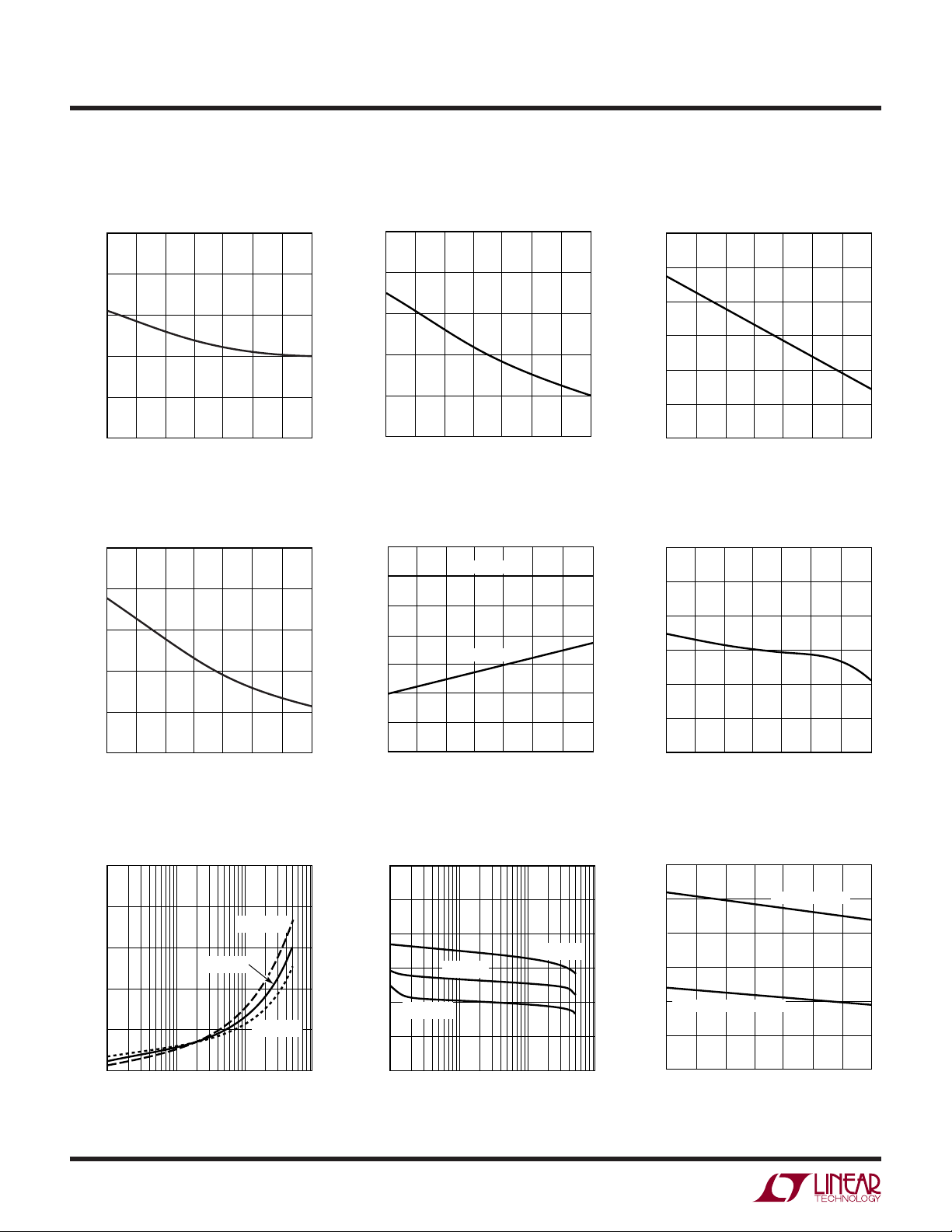
TYPICAL PERFOR A CE CHARACTERISTICS
Minimum Input Voltage vs
Temperature Shutdown I
4.3
4.2
4.1
4.0
3.9
MINIMUM INPUT VOLTAGE (V)
3.8
–50
–25
25
0
TEMPERATURE (°C)
50
75
100
125
1737 G01
125
100
(µA)
75
CC
50
SHUTDOWN I
25
0
–50
UVLO Pin Input Current vs
Supply Current vs Temperature
13
12
11
10
SUPPLY CURRENT (mA)
9
Temperature
1
0
–1
–2
–3
–4
UVLO PIN INPUT CURRENT (µA)
–5
0
–25
TEMPERATURE (°C)
vs Temperature
CC
50
V
UVLO
V
25
UVLO
75
= 1.2V
= 1.3V
100
1737 G02
125
Shutdown Voltage (V
Temperature
1.0
0.9
(V)
UVLO
0.8
0.7
0.6
SHUTDOWN VOLTAGE V
0.5
0.4
–50
–25 0
25 75
TEMPERATURE (°C)
Oscillator Frequency vs
Temperature
115
110
105
100
95
OSCILLATOR FREQUENCY (kHz)
90
) vs
UVLO
50 100 125
1737 G03
(V)
GATE
V
4
1.0
0.8
0.6
0.4
0.2
8
0
–50
V
1
–25
GATE
0
TEMPERATURE (°C)
vs I
SINK
10 100 1000
I
SINK
75
TA = 125°C
TA = 25°C
(mA)
50
25
100
1737 G04
TA = –55°C
1737 G07
125
–0.5
–1.0
(V)
GATE
–1.5
-V
CC
V
–2.0
–2.5
–3.0
–6
–50
0
1
–25 0
VCC-V
TA = –55°C
50 100 125
25 75
TEMPERATURE (°C)
vs I
GATE
SOURCE
TA = 125°C
TA = 25°C
10 100 1000
I
(mA)
SOURCE
1737 G05
1737 G08
85
–50
–25 0
TEMPERATURE (°C)
50 100 125
25 75
VC Clamp Voltage, Switching
Threshold vs Temperature
3.0
2.5
2.0
1.5
1.0
SWITCHING THRESHOLD
0.5
CLAMP VOLTAGE, SWITCHING THRESHOLD (V)
C
0
V
–50
–25 0
TEMPERATURE (°C)
CLAMP VOLTAGE
50 100 125
25 75
1737 G06
1737 G09
1737fa
UW
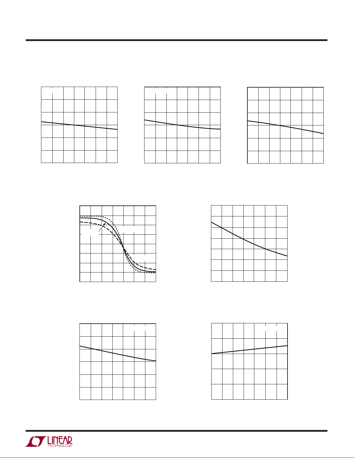
TYPICAL PERFOR A CE CHARACTERISTICS
LT1737
Minimum Switch On Time vs
Temperature
275
R
= 50k
TON
250
225
200
175
MINIMUM SWITCH ON TIME (ns)
150
125
–50
–25 0
25 75
TEMPERATURE (°C)
Feedback Amplifier Output Current
vs FB Pin Voltage
80
60
40
20
0
–20
–40
–60
FEEDBACK AMPLIFIER OUTPUT CURRENT (µA)
–80
1.05
Minimum Enable Time vs
Temperature
275
250
225
200
175
MINIMUM ENABLE TIME (ns)
150
50 100 125
1737 G10
TA = 25°C
1.15 1.25
1.10 1.20 1.30 1.40
TA = –55°C
FB PIN VOLTAGE (V)
125
–50
TA = 125°C
1.35
R
MINENAB
–25 0
1737 G13
= 50k
25 75
TEMPERATURE (°C)
50 100 125
1737 G11
Feedback Amplifier
Transconductance vs Temperature
1600
1400
1200
1000
800
600
400
200
–50
FEEDBACK AMPLIFIER TRANSCONDUCTANCE (µmho)
–25 0
Enable Delay Time vs
Temperature
275
250
225
200
175
ENABLE DELAY TIME (ns)
150
125
–50
–25 0
50 100 125
25 75
TEMPERATURE (°C)
50 100 125
25 75
TEMPERATURE (°C)
1737 G14
1737 G12
Soft-Start Charging Current vs
Temperature
60
50
40
30
20
10
SOFT-START CHARGING CURRENT (µA)
0
–50
–25 0
TEMPERATURE (°C)
50 100 125
25 75
V(SFST) = 0V
1737 G15
Soft-Start Sink Current vs
Temperature
2.5
2.0
1.5
1.0
0.5
SOFT-START SINK CURRENT (mA)
0
–50
0
–25
TEMPERATURE (°C)
50
25
V(SFST) = 1.5V
75
100
125
1737 G16
1737fa
5

LT1737
U
UU
PI FU CTIO S
PGND (Pin 1): The power ground pin carries the GATE
node discharge current. This is typically a current spike of
several hundred mA with a duration of tens of nanoseconds. It should be connected directly to a good quality
ground plane.
(Pin 2): Pin to measure switch current with external
I
SENSE
sense resistor. The sense resistor should be of a noninductive construction as high speed performance is essential. Proper grounding technique is also required to avoid
distortion of the high speed current waveform. A preset
internal limit of nominally 250mV at this pin effects a
switch current limit.
SFST (Pin 3): Pin for optional external capacitor to effect
soft-start function. See Applications Information for
details.
R
(Pin 4): Input pin for optional external load com-
OCMP
pensation resistor. Use of this pin allows nominal compensation for nonzero output impedance in the power
transformer secondary circuit, including secondary winding impedance, output Schottky diode impedance and
output capacitor ESR. In less demanding applications, this
resistor is not needed. See Applications Information for
more details.
R
(Pin 5): Pin for external filter capacitor for optional
CMPC
load compensation function. A common 0.1µF ceramic
capacitor will suffice for most applications. See Applications Information for further details.
OSCAP (Pin 6): Pin for external timing capacitor to set
oscillator switching frequency. See Applications Information for details.
VC (pin 7):
output of the feedback amplifier and the input of the
current comparator. Frequency compensation of the
overall loop is effected in most cases by placing a
capacitor between this node and ground.
This is the control voltage pin which is the
3V
(Pin 9): Output pin for nominal 3V reference. This
OUT
facilitates various user applications. This node is internally
current limited for protection and is intended to drive
either moderate capacitive loads of several hundred pF or
less, or, very large capacitive loads of 0.1µF or more. See
Applications Information for more details.
UVLO (Pin 10): This is a dual function pin that implements
both undervoltage lockout and shutdown functions. Pulling this pin to near ground effects shutdown and reduces
quiescent current to tens of microamperes.
Additionally, an external resistor divider between VIN and
ground may be connected to this pin to implement an
undervoltage lockout function. The bias current on this pin
is a function of the state of the UVLO comparator; as the
threshold is exceeded, the bias current increases. This
creates a hysteresis band equal to the change in bias
current times the Thevenin impedance of the user’s resistive divider. The user may thereby adjust the impedance of
the UVLO divider to achieve a desired degree of hysteresis.
A 100pF capacitor to ground is recommended on this pin.
See Application Information for details.
SGND (Pin 11): The signal ground pin is a clean ground.
The internal reference, oscillator and feedback amplifier
are referred to it. Keep the ground path connection to the
FB pin, OSCAP capacitor and the VC compensation capacitor free of large ground currents.
MINENAB (Pin 12): Pin for external programming resistor
to set minimum enable time. See Applications Information
for details.
ENDLY (Pin 13): Pin for external programming resistor to
set enable delay time. See Applications Information for
details.
tON (Pin 14): Pin for external programming resistor to set
switch minimum on time. See Applications Information
for details.
FB (Pin 8): Input pin for external “feedback” resistor
divider. The ratio of this divider, times the internal bandgap (VBG) reference, times the effective transformer turns
ratio is the primary determinant of the output voltage. The
Thevenin equivalent resistance of the feedback divider
should be roughly 3k. See Applications Information for
more details.
6
VCC (Pin 15): Supply voltage for the LT1737. Bypass this
pin to ground with 1µF or more.
GATE (Pin 16): This is the gate drive to the external power
MOSFET switch and has large dynamic currents flowing
through it. Keep the trace to the MOSFET as short as
possible to minimize electromagnetic radiation and voltage spikes. A series resistance of 5Ω or more may help to
dampen ringing in less than ideal layouts.
1737fa
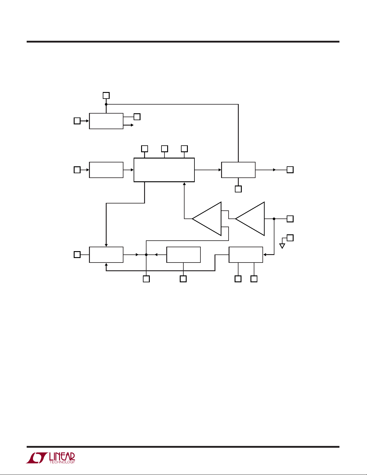
BLOCK DIAGRA
UVLO
BIAS
V
W
CC
3V
OUT
3V REG
(INTERNAL)
LT1737
OSCAP
FB
OSC
FDBK
MINENABt
ON
LOGIC
V
C
ENDLY
MOSFET
DRIVER
PGND
COMP
SOFT-START
SFST R
COMPENSATION
R
OCMP
LOAD
I
AMP
CMPC
1737 BD
GATE
I
SENSE
SGND
1737fa
7

LT1737
UWW
TI I G DIAGRA
V
SW
VOLTAGE
V
IN
GND
SWITCH
STATE
OFF ON
MINIMUM t
ON
FLYBACK AMP
STATE
ENABLE DELAY
MINIMUM ENABLE TIME
V
FLBK
OFF ON
ENABLEDDISABLED DISABLED
0.80×
V
FLBK
COLLAPSE
DETECT
1737 TD
W
FLYBACK ERROR A PLIFIER
V
IN
M1
R1
FB
Q1 Q2
R2
I
T1
•
D1
•
+
C1
+
ISOLATED
V
OUT
–
•
I
M
V
BG
I
FXD
V
C
ENAB
C2
I
M
1737 EA
8
1737fa

OPERATIO
LT1737
U
The LT1737 is a current mode switcher controller IC
designed specifically for the isolated flyback topology. The
Block Diagram shows an overall view of the system. Many
of the blocks are similar to those found in traditional
designs, including: Internal Bias Regulator, Oscillator,
Logic, Current Amplifier and Comparator, Driver and Output Switch. The novel sections include a special Flyback
Error Amplifier and a Load Compensation mechanism.
Also, due to the special dynamic requirements of flyback
control, the Logic system contains additional functionality
not found in conventional designs.
The LT1737 operates much the same as traditional current
mode switchers, the major difference being a different
type of error amplifier that derives its feedback information from the flyback pulse. Due to space constraints, this
discussion will not reiterate the basics of current mode
switcher/controllers and isolated flyback converters. A
good source of information on these topics is Application
Note AN19.
ERROR AMPLIFIER—PSEUDO DC THEORY
Please refer to the simplified diagram of the Flyback Error
Amplifier. Operation is as follows: when MOSFET output
switch M1 turns off, its drain voltage rises above the V
IN
rail. The amplitude of this flyback pulse as seen on the third
winding is given as:
V V I ESR
V
FLBK
=
N
++
()
OUT F SEC
•
ST
The relatively high gain in the overall loop will then cause
the voltage at the FB pin to be nearly equal to the bandgap
reference V
. The relationship between V
BG
FLBK
and V
BG
may then be expressed as:
RR
+
12
V
FLBK BG
()
=
Combination with the previous V
expression for V
V
R
2
expression yields an
FLBK
in terms of the internal reference,
OUT
programming resistors, transformer turns ratio and diode
forward voltage drop:
VV
=
OUT BG
12
()
RN
⎛
⎞
1
V I ESR
–– •
⎟
⎠
F SEC
⎜
2
⎝
ST
RR
+
Additionally, it includes the effect of nonzero secondary
output impedance, which is discussed in further detail, see
Load Compensation Theory. The practical aspects of
applying this equation for V
are found in the Applica-
OUT
tions Information section.
So far, this has been a pseudo-DC treatment of flyback
error amplifier operation. But the flyback signal is a pulse,
not a DC level. Provision must be made to enable the
flyback amplifier only when the flyback pulse is present.
This is accomplished by the dotted line connections to the
block labeled “ENAB”. Timing signals are then required to
enable and disable the flyback amplifier.
ERROR AMPLIFIER—DYNAMIC THEORY
VF = D1 forward voltage
I
= transformer secondary current
SEC
ESR = total impedance of secondary circuit
NST = transformer effective secondary-to-third
winding turns ratio
The flyback voltage is then scaled by external resistor
divider R1/R2 and presented at the FB pin. This is then
compared to the internal bandgap reference by the differential transistor pair Q1/Q2. The collector current from Q1
is mirrored around and subtracted from fixed current
source I
at the VC pin. An external capacitor integrates
FXD
this net current to provide the control voltage to set the
current mode trip point.
There are several timing signals that are required for
proper LT1737 operation. Please refer to the Timing
Diagram.
Minimum Output Switch On Time
The LT1737 effects output voltage regulation via flyback
pulse action. If the output switch is not turned on at all,
there will be no flyback pulse and output voltage information is no longer available. This would cause irregular loop
response and start-up/latchup problems. The solution chosen is to require the output switch to be on for an absolute
minimum time per each oscillator cycle. This in turn establishes a minimum load requirement to maintain regulation. See Applications Information for further details.
1737fa
9

LT1737
OPERATIO
U
Enable Delay
When the output switch shuts off, the flyback pulse
appears. However, it takes a finite time until the transformer primary side voltage waveform approximately represents the output voltage. This is partly due to finite rise
time on the MOSFET drain node, but more importantly,
due to transformer leakage inductance. The latter causes
a voltage spike on the primary side not directly related to
output voltage. (Some time is also required for internal
settling of the feedback amplifier circuitry.)
In order to maintain immunity to these phenomena, a fixed
delay is introduced between the switch turnoff command
and the enabling of the feedback amplifier. This is termed
enable delay. In certain cases where the leakage spike is
not sufficiently settled by the end of the enable delay
period, regulation error may result. See Application Information for further details.
Collapse Detect
Once the feedback amplifier is enabled, some mechanism
is then required to disable it. This is accomplished by a
collapse detect comparator, which compares the flyback
voltage (FB referred) to a fixed reference, nominally 80%
of VBG. When the flyback waveform drops below this
level, the feedback amplifier is disabled. This action
accommodates both continuous and discontinuous mode
operation.
Minimum Enable Time
The feedback amplifier, once enabled, stays enabled for a
fixed minimum time period termed “minimum enable
time.” This prevents lockup, especially when the output
voltage is abnormally low, e.g., during start-up. The minimum enable time period ensures that the V
node is able
C
to “pump up” and increase the current mode trip point to
the level where the collapse detect system exhibits proper
operation. The “minimum enable time” often determines
the low load level at which output voltage regulation is lost.
See Applications Information for details.
Effects of Variable Enable Period
It should now be clear that the flyback amplifier is enabled
during only a portion of the cycle time. This can vary from
the fixed “minimum enable time” described to a maximum
of roughly the “off” switch time minus the enable delay
time. Certain parameters of flyback amp behavior will then
be directly affected by the variable enable period. These
include effective transconductance and V
node slew rate.
C
LOAD COMPENSATION THEORY
The LT1737 uses the flyback pulse to obtain information
about the isolated output voltage. A potential error source
is caused by transformer secondary current flow through
the real life nonzero impedances of the output rectifier,
T1
10
R1
R2
FB
LOAD
COMP I
Q1 Q2
I
M
+
Q3
V
BG
I
M
Figure 1. Load Compensation Diagram
R
OCMP
A1
–
R
R3
50k
CMPC
I
SENSE
V
IN
M1
R
SENSE
1737 F01
1737fa

OPERATIO
LT1737
U
transformer secondary and output capacitor. This has
been represented previously by the expression “I
SEC
•
ESR.” However, it is generally more useful to convert this
expression to an effective output impedance. Because the
secondary current only flows during the off portion of the
duty cycle, the effective output impedance equals the
lumped secondary impedance times the inverse of the OFF
duty cycle. That is:
R ESR
=
OUT
R
= effective supply output impedance
OUT
⎛
⎜
DC
⎝
1
OFF
⎞
where
⎟
⎠
ESR = lumped secondary impedance
DC
= OFF duty cycle
OFF
Expressing this in terms of the ON duty cycle, remembering DC
R ESR
OFF
OUT
= 1 – DC,
⎛
=
⎜
1–
⎝
1
DC
⎞
⎟
⎠
DC = ON duty cycle
In less critical applications, or if output load current
remains relatively constant, this output impedance error
may be judged acceptable and the external FB resistor
divider adjusted to compensate for nominal expected
error. In more demanding applications, output impedance
error may be minimized by the use of the load compensation function.
To implement the load compensation function, a voltage is
developed that is proportional to average output switch
current. This voltage is then impressed across the external
R
resistor, and the resulting current acts to decrease
OCMP
the voltage at the FB pin. As output loading increases,
average switch current increases to maintain rough output
voltage regulation. This causes an increase in R
OCMP
resistor current which effects a corresponding increase in
flyback voltage amplitude.
Assuming a relatively fixed power supply efficiency, Eff,
Power Out = Eff • Power In
V
• I
OUT
= Eff • VIN • I
OUT
IN
Average primary side current may be expressed in terms
of output current as follows:
⎛
I
=
IN
⎜
V Eff
⎝
V
IN
OUT
•
⎞
•
I
OUT
⎟
⎠
combining the efficiency and voltage terms in a single
variable:
= K1 • I
I
IN
K
1=
⎛
⎜
V Eff
⎝
V
IN
OUT
OUT
•
, where
⎞
⎟
⎠
Switch current is converted to voltage by the external
sense resistor and averaged/lowpass filtered by R3 and
the external capacitor on R
impressed across the external R
. This voltage is then
CMPC
resistor by op amp
OCMP
A1 and transistor Q3. This produces a current at the
collector of Q3 which is then mirrored around and then
subtracted from the FB node. This action effectively increases the voltage required at the top of the R1/R2
feedback divider to achieve equilibrium. So the effective
change in V
VKI
∆ = ∆
OUT OUT
∆
V
OUT
∆
I
OUT
target is:
OUT
⎛
112
••(||)
()
⎛
R
=
SENSE
K
112
⎜
R
⎝
OCMP
R
⎜
R
⎝
⎞
•( || )
⎟
⎠
SENSE
OCMP
RR
⎞
RRor
⎟
⎠
Nominal output impedance cancellation is obtained by
equating this expression with R
⎛
R
RK
OUT
RK
OCMP
112
=
⎜
R
⎝
⎛
=
112
⎜
⎝
SENSE
OCMP
R
SENSE
R
OUT
⎞
•( || )
R R and
⎟
⎠
⎞
•( || )
R R where
⎟
⎠
K1 = dimensionless variable related to VIN, V
OUT
:
and
OUT
efficiency as above
R
R
= external sense resistor
SENSE
= uncompensated output impedance
OUT
(R1||R2) = impedance of R1 and R2 in parallel
The practical aspects of applying this equation to determine an appropriate value for the R
resistor are found
OCMP
in the Applications Information section.
1737fa
11

LT1737
WUUU
APPLICATIO S I FOR ATIO
TRANSFORMER DESIGN CONSIDERATIONS
Transformer specification and design is perhaps the most
critical part of applying the LT1737 successfully. In addition to the usual list of caveats dealing with high frequency
isolated power supply transformer design, the following
information should prove useful.
Turns Ratios
Note that due to the use of the external feedback resistor
divider ratio to set output voltage, the user has relative
freedom in selecting transformer turns ratio to suit a given
application. In other words, “screwball” turns ratios like
“1.736:1.0” can scrupulously be avoided! In contrast,
simpler ratios of small integers, e.g., 1:1, 2:1, 3:2, etc. can
be employed which yield more freedom in setting total
turns and mutual inductance. Turns ratio can then be
chosen on the basis of desired duty cycle. However,
remember that the input supply voltage plus the secondary-to-primary referred version of the flyback pulse (including leakage spike) must not exceed the allowed external
MOSFET breakdown rating.
Leakage Inductance
As a rough guide, total leakage inductances of several
percent (of mutual inductance) or less may require a
snubber, but exhibit little to no regulation error due to
leakage spike behavior. Inductances from several percent
up to perhaps ten percent cause increasing regulation
error.
Severe leakage inductances in the double digit percentage
range should be avoided if at all possible as there is a
potential for abrupt loss of control at high load current.
This curious condition potentially occurs when the leakage spike becomes such a large portion of the flyback
waveform that the processing circuitry is fooled into
thinking that the leakage spike itself is the real flyback
signal! It then reverts to a potentially stable state whereby
the top of the leakage spike is the control point, and the
trailing edge of the leakage spike triggers the collapse
detect circuitry. This will typically reduce the output voltage abruptly to a fraction, perhaps between one-third to
two-thirds of its correct value. If load current is reduced
sufficiently, the system will snap back to normal operation. When using transformers with considerable leakage
inductance, it is important to exercise this worst-case
check for potential bistability:
Transformer leakage inductance (on either the primary or
secondary) causes a spike after output switch turnoff. This
is increasingly prominent at higher load currents, where
more stored energy must be dissipated. In many cases a
“snubber” circuit will be required to avoid overvoltage
breakdown at the output switch node. Application Note
AN19 is a good reference on snubber design.
In situations where the flyback pulse extends beyond the
enable delay time, the output voltage regulation will be
affected to some degree. It is important to realize that the
feedback system has a deliberately limited input range,
roughly ± 50mV referred to the FB node, and this works to
the user’s advantage in rejecting large, i.e., higher voltage,
leakage spikes. In other words, once a leakage spike is
several volts in amplitude, a further increase in amplitude
has little effect on the feedback system. So the user is
generally advised to arrange the snubber circuit to clamp
at as high a voltage as comfortably possible, observing
MOSFET breakdown, such that leakage spike duration is
as short as possible.
1. Operate the prototype supply at maximum expected
load current.
2. Temporarily short circuit the output.
3. Observe that normal operation is restored.
If the output voltage is found to hang up at an abnormally
low value, the system has a problem. This will usually be
evident by simultaneously monitoring the VSW waveform
on an oscilloscope to observe leakage spike behavior
firsthand. A final note—the susceptibility of the system to
bistable behavior is somewhat a function of the load I/V
characteristics. A load with resistive, i.e., I = V/R behavior
is the most susceptible to bistability. Loads which exhibit
“CMOSsy”, i.e., I = V2/R behavior are less susceptible.
Secondary Leakage Inductance
In addition to the previously described effects of leakage
inductance in general, leakage inductance on the secondary in particular exhibits an additional phenomenon. It
forms an inductive divider on the transformer secondary,
1737fa
12

WUUU
APPLICATIO S I FOR ATIO
LT1737
which reduces the size of the primary-referred flyback
pulse used for feedback. This will increase the output
voltage target by a similar percentage. Note that unlike
leakage
spike
behavior, this phenomena is load independent. To the extent that the secondary leakage inductance
is a constant percentage of mutual inductance (over
manufacturing variations), this can be accommodated by
adjusting the feedback resistor divider ratio.
Winding Resistance Effects
Resistance in either the primary or secondary will act to
reduce overall efficiency (P
OUT/PIN
). Resistance in the
secondary increases effective output impedance which
degrades load regulation, (at least before load compensation is employed).
Bifilar Winding
A bifilar or similar winding technique is a good way to
minimize troublesome leakage inductances. However, remember that this will increase primary-to-secondary capacitance and limit the primary-to-secondary breakdown
voltage, so bifilar winding is not always practical.
Finally, the LTC Applications group is available to assist
in the choice and/or design of the transformer. Happy
Winding!
two unknowns” is obtained from noting that the Thevenin
impedance of the resistor divider should be roughly 3k for
bias current cancellation and other reasons.
SELECTING R
RESISTOR VALUE
OCMP
The Operation section previously derived the following
expressions for R
R
, the external resistor value required for its nominal
OCMP
, i.e., effective output impedance and
OUT
compensation:
R ESR
OUT
RK
OCMP
⎛
=
⎜
⎝
⎛
=
112
⎜
⎝
While the value for R
1
–
R
SENSE
R
⎞
1
⎟
DC
⎠
⎞
||
RR
()
⎟
⎠
OUT
may therefore be theoretically
OCMP
determined, it is usually better in practice to employ
empirical methods. This is because several of the required
input variables are difficult to estimate precisely. For
instance, the ESR term above includes that of the transformer secondary, but its effective ESR value depends on
high frequency behavior, not simply DC winding resistance. Similarly, K1 appears to be a simple ratio of VIN to
V
times (differential) efficiency, but theoretically esti-
OUT
mating efficiency is not a simple calculation. The suggested empirical method is as follows:
SELECTING FEEDBACK RESISTOR DIVIDER VALUES
The expression for V
developed in the Operation sec-
OUT
tion can be rearranged to yield the following expression for
the R1/R2 ratio:
RR
12
+
()
R
V
OUT
=
2
= desired output voltage
++
V V I ESR
()
OUT F SEC
V
BG
•
N
ST
where:
VF = switching diode forward voltage
I
• ESR = secondary resistive losses
SEC
VBG = data sheet reference voltage value
NST = effective secondary-to-third winding turns ratio
The above equation defines only the ratio of R1 to R2, not
their individual values. However, a “second equation for
Build a prototype of the desired supply using the eventual
secondary components. Temporarily ground the R
CMPC
pin to disable the load compensation function. Operate the
supply over the expected range of output current loading
while measuring the output voltage deviation. Approximate this variation as a single value of R
(straight line
OUT
approximation). Calculate a value for the K1 constant
based on VIN, V
ciency. These are then combined with R
to yield a value for R
and the measured (differential) effi-
OUT
as indicated
SENSE
.
OCMP
Verify this result by connecting a resistor of roughly this
value from the R
ground short to R
pin to ground. (Disconnect the
OCMP
and connect the requisite 0.1µF
CMPC
filter capacitor to ground.) Measure the output impedance
with the new compensation in place. Modify the original
R
value if necessary to increase or decrease the
OCMP
effective compensation.
1737fa
13

LT1737
WUUU
APPLICATIO S I FOR ATIO
SELECTING OSCILLATOR CAPACITOR VALUE
The switching frequency of the LT1737 is set by an
external capacitor connected between the OSCAP pin and
ground. Recommended values are between 200pF and
33pF, yielding switching frequencies between 50kHz and
250kHz. Figure 2 shows the nominal relationship between
external capacitance and switching frequency. To minimize stray capacitance and potential noise pickup, this
capacitor should be placed as close as possible to the IC
and the OSCAP node length/area minimized.
300
(Hz)
OSC
f
100
50
30
Figure 2. f
OSC
100 200
C
(pF)
OSCAP
vs OSCAP Value
1737 F02
1000
500
TIME (ns)
100
20
Figure 3. “One Shot” Times vs Programming Resistor
100 250
RT (kΩ)
1737 F03
indicative of actual current level in the transformer primary, and may cause irregular current mode switching
action, especially at light load.
However, the user must remember that the LT1737 does
not “skip cycles” at light loads. Therefore, minimum on
time will set a limit on minimum delivered power and consequently a minimum load requirement to maintain regulation (see Minimum Load Considerations). Similarly,
minimum on time has a direct effect on short-circuit behavior (see Maximum Load/Short-Circuit Considerations).
SELECTING TIMING RESISTOR VALUES
There are three internal “one-shot” times that are programmed by external application resistors: minimum on
time, enable delay time and minimum enable time. These
are all part of the isolated flyback control technique, and
their functions have been previously outlined in the Operation section. Figure 3 shows nominal observed time versus external resistor value for these functions.
The following information should help in selecting and/or
optimizing these timing values.
Minimum On Time
This time defines a period whereby the normal switch
current limit is ignored. This feature provides immunity to
the leading edge current spike often seen at the source
node of the external power MOSFET, due to rapid charging
of its gate/source capacitance. This current spike is not
The user is normally tempted to set the minimum on time
to be short to minimize these load related consequences.
(After all, a smaller minimum on time approaches the ideal
case of zero, or no minimum.) However, a longer time may
be required in certain applications based on MOSFET
switching current spike considerations.
Enable Delay Time
This function provides a programmed delay between
turnoff of the gate drive node and the subsequent enabling
of the feedback amplifier. At high loads, a primary side
voltage spike after MOSFET turnoff may be observed due
to transformer leakage inductance. This spike is not indicative of actual output voltage (see Figure 4B). Delaying
the enabling of the feedback amplifier allows this system
to effectively ignore most or all of the voltage spike and
maintain proper output voltage regulation. The enable
delay time should therefore be set to the maximum expected duration of the leakage spike. This may have
1737fa
14

WUUU
APPLICATIO S I FOR ATIO
LT1737
implications regarding output voltage regulation at minimum load (see Minimum Load Considerations).
A second benefit of the enable delay time function occurs
at light load. Under such conditions the amount of energy
stored in the transformer is small. The flyback waveform
becomes “lazy” and some time elapses before it indicates
the actual secondary output voltage (see Figure 4C). So
the enable delay time should also be set long enough to
ignore the “irrelevant” portion of the flyback waveform at
light load.
Additionally, there are cases wherein the gate output is
called upon to drive a large geometry MOSFET such that
the turnoff transition is slowed significantly. Under such
circumstances, the enable delay time may be increased to
accommodate for the lengthy transition.
MOSFET GATE DRIVE
A
IDEALIZED FLYBACK
WAVEFORM
Average “start-up” VC current =
MinimumEnable Time
SwitchingFrequency
•
I
SRC
Minimum enable time can also have implications at light
load (see Minimum Load Considerations). The temptation
is to set the minimum enable time to be fairly short, as this
is the least restrictive in terms of minimum load behavior.
However, to provide a “reliable” minimum start-up current
of say, nominally 1µA, the user should set the minimum
enable time at no less that 2% of the switching period
(= 1/switching frequency).
CURRENT SENSE RESISTOR CONSIDERATIONS
The external current sense resistor allows the user to
optimize the current limit behavior for the particular application under consideration. As the current sense resistor
is varied from several ohms down to tens of milliohms,
peak switch current goes from a fraction of an ampere to
tens of amperes. Care must be taken to ensure proper
circuit operation, especially with small current sense
resistor values.
FLYBACK WAVEFORM
B
C
ENABLE
DELAY
TIME
NEEDED
ENABLE DELAY
TIME NEEDED
DISCONTINUOUS
Figure 4
MODE
RINGING
WITH LARGE LEAKAGE
SPIKE AT HEAVY LOAD
“SLOW” FLYBACK
WAVEFORM AT
LIGHT LOAD
1737 F04
Minimum Enable Time
This function sets a minimum duration for the expected
flyback pulse. Its primary purpose is to provide a minimum source current at the VC node to avoid start-up
problems.
For example, a peak switch current of 10A requires a
sense resistor of 0.025Ω. Note that the instantaneous
peak power in the sense resistor is 2.5W, and it must be
rated accordingly. The LT1737 has only a single sense line
to this resistor. Therefore, any parasitic resistance in the
ground side connection of the sense resistor will increase
its apparent value. In the case of a 0.025Ω sense resistor,
one milliohm
of parasitic resistance will cause a 4%
reduction in peak switch current. So resistance of printed
circuit copper traces and vias cannot necessarily be
ignored.
An additional consideration is parasitic inductance. Inductance in series with the current sense resistor will
accentuate the high frequency components of the current
waveform. In particular, the gate switching spike and
multimegahertz ringing at the MOSFET can be
considerably amplified. If severe enough, this can cause
erratic operation. For example, assume 3nH of parasitic
inductance (equivalent to about 0.1 inch of wire in free
space) is in series with an ideal 0.025Ω sense resistor.
A “zero” will be formed at f = R/(2πL), or 1.3MHz. Above
1737fa
15

LT1737
WUUU
APPLICATIO S I FOR ATIO
this frequency the sense resistor will behave like an
inductor.
Several techniques can be used to tame this potential
parasitic inductance problem. First, any resistor used for
current sensing purposes must be of an inherently noninductive construction. Mounting this resistor directly
above an unbroken ground plane and minimizing its
ground side connection will serve to absolutely minimize
parasitic inductance. In the case of low valued sense
resistors, these may be implemented as a parallel combination of several resistors for the thermal considerations
cited above. The parallel combination will help to lower the
parasitic inductance. Finally, it may be necessary to place
a “pole” between the current sense resistor and the
LT1737 I
pin to undo the action of the inductive zero
SENSE
(see Figure 5). A value of 51Ω is suggested for the resistor,
while the capacitor is selected empirically for the particular
application and layout. Using good high frequency measurement techniques, the I
pin waveform may be
SENSE
observed directly with an oscilloscope while the capacitor
value is varied.
SENSE RESISTOR ZERO AT:
R
SENSE
f =
2πL
P
COMPENSATING POLE AT:
FOR CANCELLATION:
f =
2π(51Ω)C
C
COMP
1
COMP
L
P
=
R
(51Ω)
SENSE
PGNDSGND
GATE
I
SENSE
51Ω
C
COMP
PARASITIC
INDUCTANCE
R
SENSE
L
P
1737 F05
Figure 5
SOFT-START FUNCTION
The LT1737 contains an optional soft-start function that is
enabled by connecting an explicit external capacitor between the SFST pin and ground. Internal circuitry prevents
the control voltage at the VC pin from exceeding that on the
SFST pin.
Th
e soft-start function is enagaged whenever VCC power
is removed, or as a result of either undervoltage lockout
or thermal (overtemperature) shutdown. The SFST node
is then discharged rapidly to roughly a VBE above ground.
(Remember that the VC pin control node switching
threshold is deliberately set at a VBE
plus
several hundred
millivolts.) When this condition is removed, a nominal
40µA current acts to charge up the SFST node towards
roughly 3V. So, for example, a 0.1µF soft-start capacitor
will place a 0.4V/ms limit on the ramp rate at the VC node.
UVLO PIN FUNCTION
The UVLO pin effects both undervoltage lockout and
shutdown functions. This is accomplished by using different voltage thresholds for the two functions—the shutdown function is at roughly a V
above ground (0.75V at
BE
25°C, large temperature variation), while the UVLO function is at nearly a bandgap voltage (1.25V, fairly stable with
temperature). An external resistor divider between the
input supply and ground can then be used to achieve a
user-programmable undervoltage lockout (see Figure 6a).
An additional feature of this pin is that there is a change in
the input bias current at this pin as a function of the state
of the internal UVLO comparator. As the pin is brought
above the UVLO threshold, the bias current sourced by the
part increases. This positive feedback effects a hysteresis
band for reliable switching action. Note that the size of the
hysteresis is proportional to the Thevenin impedance of
the external UVLO resistor divider network, which makes
it user programmable. As a rough rule of thumb, each 4k
or so of impedance generates about 1% of hysteresis.
(This is based on roughly 1.25V for the threshold and 3µA
for the bias current shift.)
Even in good quality ground plane layouts, it is common
for the switching node (MOSFET drain) to couple to the
UVLO pin with a stray capacitance of several
thousandths
of a pF. To ensure proper UVLO action, a 100pF capacitor
is recommended from this pin to ground as shown in
Figure 6b. This will typically reduce the coupled noise to
a few millivolts. The UVLO filter capacitor should not be
made much larger than a few hundred pF, however, as the
hysteresis action will become too slow. In cases where
further filtering is required, e.g., to attenuate high speed
supply ripple, the topology in Figure 6c is recommended.
Resistor R1 has been split into two equal parts. This
provides a node for effecting capacitor filtering of high
speed supply ripple, while leaving the UVLO pin node
impedance relatively unchanged at high frequency.
1737fa
16

WUUU
APPLICATIO S I FOR ATIO
LT1737
V
IN
V
IN
R1
UVLO
R2
(6a) “Standard” UVLO
Divider Topology
(6b) Filter Capacitor
Directly on UVLO Note
C1
100pF
V
IN
R1
R2
Figure 6
FREQUENCY COMPENSATION
Loop frequency compensation is performed by connecting a capacitor from the output of the error amplifier (V
C
pin) to ground. An additional series resistor, often required in traditional current mode switcher controllers, is
usually not required and can even prove detrimental. The
phase margin improvement traditionally offered by this
extra resistor will usually be already accomplished by the
nonzero secondary circuit impedance, which adds a “zero”
to the loop response.
In further contrast to traditional current mode switchers,
VC pin ripple is generally not an issue with the LT1737. The
dynamic nature of the clamped feedback amplifier forms
an effective track/hold type response, whereby the V
C
voltage changes during the flyback pulse, but is then “held”
during the subsequent “switch on” portion of the next
cycle. This action naturally holds the VC voltage stable
during the current comparator sense action (current mode
switching).
OUTPUT VOLTAGE ERROR SOURCES
R1/2
C2
R1/2
UVLO
C1
100pF
(6c) Recommended Topology to
Filter High Frequency Ripple
UVLO
R2
1737 F06
Internal Voltage Reference
The internal bandgap voltage reference is, of course,
imperfect. Its error, both at 25°C and over temperature is
already included in the specifications.
User Programming Resistors
Output voltage is controlled by the user-supplied feedback
resistor divider ratio. To the extent that the resistor ratio
differs from the ideal value, the output voltage will be
proportionally affected. Highest accuracy systems will
demand 1% components.
Schottky Diode Drop
The LT1737 senses the output voltage from the transformer primary side during the flyback portion of the
cycle. This sensed voltage therefore includes the forward
drop, VF, of the rectifier (usually a Schottky diode). The
nominal VF of this diode should therefore be included in
feedback resistor divider calculations. Lot to lot and
ambient temperature variations will show up as output
voltage shift/drift.
Conventional nonisolated switching power supply ICs
typically have only two substantial sources of output
voltage error: the internal or external resistor divider
network that connects to V
and the internal IC refer-
OUT
ence. The LT1737, which senses the output voltage in both
a dynamic and an isolated manner, exhibits additional
potential error sources to contend with. Some of these
errors are proportional to output voltage, others are fixed
in an absolute millivolt sense. Here is a list of possible
error sources and their effective contribution.
Secondary Leakage Inductance
Leakage inductance on the transformer secondary reduces the effective secondary-to-third winding turns ratio
(NS/NT) from its ideal value. This will increase the output
voltage target by a similar percentage. To the extent that
secondary leakage inductance is constant from part to
part, this can be accommodated by adjusting the feedback
resistor ratio.
1737fa
17

LT1737
Minimum Power
f
L
Vtt
VI
SEC
OUT EN ED
OUT OUT
=
⎛
⎝
⎜
⎞
⎠
⎟
+
()
[]
=
1
2
2
•
•
WUUU
APPLICATIO S I FOR ATIO
Output Impedance Error
An additional error source is caused by transformer secondary current flow through the real life nonzero impedances of the output rectifier, transformer secondary and
output capacitor. Because the secondary current only
flows during the off portion of the duty cycle, the effective
output impedance equals the “DC” lumped secondary
impedance times the inverse of the off duty cycle. If the
output load current remains relatively constant, or, in less
critical applications, the error may be judged acceptable
and the feedback resistor divider ratio adjusted for nominal expected error. In more demanding applications, output impedance error may be minimized by the use of the
load compensation function (see Load Compensation).
MINIMUM LOAD CONSIDERATIONS
The LT1737 generally provides better low load performance than previous generation switcher/controllers utilizing indirect output voltage sensing techniques.
Specifically, it contains circuitry to detect flyback pulse
“collapse,” thereby supporting operation well into discontinuous mode. Nevertheless, there still remain constraints
to ultimate low load operation. These relate to the minimum switch on time and the minimum enable time.
Discontinuous mode operation will be assumed in the
following theoretical derivations.
As outlined in the Operation section, the LT1737 utilizes a
minimum output switch on time, tON. This value can be
combined with expected VIN and switching frequency to
yield an expression for minimum delivered power.
Minimum Power
f
1
=
⎜
L
2
⎝
PRI
VI
=
OUT OUT
⎞
Vt
()
IN ON
⎟
⎠
•
2
•
⎛
This expression then yields a minimum output current
constraint:
I
OUT MIN
⎛
1
⎜
2
LV
⎝
PRI OUT
•
⎞
f
Vt
()
IN ON()
⎟
⎠
2
•=
where
f = switching frequency
L
= transformer primary side inductance
PRI
VIN = input voltage
V
= output voltage
OUT
tON = output switch minimum on time
An additional constraint has to do with the minimum
enable time. The LT1737 derives its output voltage information from the flyback pulse. If the internal minimum
enable time pulse extends beyond the flyback pulse, loss
of regulation will occur. The onset of this condition can be
determined by setting the width of the flyback pulse equal
to the sum of the flyback enable delay, tED, plus the
minimum enable time, tEN. Minimum power delivered to
the load is then:
Which yields a minimum output constraint:
I
OUT MIN
⎛
•
1
fV
=
⎜
2
L
⎝
⎞
OUT
tt
()
ED EN()
⎟
⎠
SEC
2
+
where
f = switching frequency
L
= transformer secondary side inductance
SEC
V
= output voltage
OUT
tED = enable delay time
tEN = minimum enable time
Note that generally, depending on the particulars of input
and output voltages and transformer inductance, one of
the above constraints will prove more restrictive. In other
words, the minimum load current in a particular application will be either “output switch minimum on time”
constrained, or “minimum flyback pulse time” constrained.
(A final note—L
PRI
and L
refer to transformer induc-
SEC
tance as seen from the primary or secondary side respectively. This general treatment allows these expressions to
be used when the transformer turns ratio is nonunity.)
18
1737fa

WUUU
APPLICATIO S I FOR ATIO
LT1737
MAXIMUM LOAD/SHORT-CIRCUIT CONSIDERATIONS
The LT1737 is a current mode controller. It uses the V
C
node voltage as an input to a current comparator that turns
off the output switch on a cycle-by-cycle basis as this peak
current is reached. The internal clamp on the V
node,
C
nominally 2.5V, then acts as an output switch peak current
limit.
This 2.5V at the VC pin corresponds to a value of 250mV
at the I
pin, when the (ON) switch duty cycle is less
SENSE
than 40%. For a duty cycle above 40%, the internal slope
compensation mechanism lowers the effective I
SENSE
voltage limit. For example, at a duty cycle of 80%, the
nominal I
voltage limit is 220mV. This action be-
SENSE
comes the switch current limit specification. Maximum
available output power is then determined by the switch
current limit, which is somewhat duty cycle dependent
due to internal slope compensation action.
Overcurrent conditions are handled by the same mechanism. The output switch turns on, the peak current is
quickly reached and the switch is turned off. Because the
output switch is only on for a small fraction of the available
period, power dissipation is controlled.
Loss of current limit is possible under certain conditions.
Remember that the LT1737 normally exhibits a minimum
switch on time, irrespective of current trip point. If the duty
cycle exhibited by this minimum on time is greater than the
ratio of secondary winding voltage (referred-to-primary)
divided by input voltage, then peak current will not be
controlled at the nominal value, and will cycle-by-cycle
ratchet up to some higher level. Expressed mathematically, the requirement to maintain short-circuit control is:
+
<
tf
•
ON
VI R
()
F SC SEC
•
VN
•
IN SP
where
tON = output switch minimum on time
f = switching frequency
Trouble is typically only encountered in applications with
a relatively high product of input voltage times secondaryto-primary turns ratio and/or a relatively long minimum
switch on time. (Additionally, several real world effects such
as transformer leakage inductance, AC winding losses, and
output switch voltage drop combine to make this simple
theoretical calculation a conservative estimate.)
THERMAL CONSIDERATIONS
Care should be taken to ensure that the worst-case input
voltage condition does not cause excessive die temperatures. The 16-lead SO package is rated at 100°C/W, and
the 16-lead GN at 110°C/W.
Average supply current is simply the sum of quiescent
current given in the specifications section plus gate drive
current. Gate drive current can be computed as:
IG = f • QG where
QG = total gate charge
f = switching frequency
(Note: Total gate charge is more complicated than CGS • V
G
as it is frequently dominated by Miller effect of the CGD.
Furthermore, both capacitances are nonlinear in practice.
Fortunately, most MOSFET data sheets provide figures
and graphs which yield the total gate charge directly per
operating conditions.) Nearly all gate drive power is dissipated in the IC, except for a small amount in the external
gate series resistor, so total IC dissipation may be computed as:
P
D(TOTAL)
= VCC (IQ + • f • QG ), where
IQ = quiescent current (from specifications)
QG = total gate charge
f = switching frequency
VCC = LT1737 supply voltage
ISC = short-circuit output current
VF = output diode forward voltage at I
R
= resistance of transformer secondary
SEC
SC
VIN = input voltage
NSP = secondary-to-primary turns ratio (N
SEC/NPRI
SWITCH NODE CONSIDERATIONS
For maximum efficiency, gate drive rise and fall times are
made as short as practical. To prevent radiation and high
frequency resonance problems, proper layout of the
components connected to the IC is essential, especially
)
1737fa
19

LT1737
WUUU
APPLICATIO S I FOR ATIO
the power paths (primary
and
secondary). B field (magnetic) radiation is minimized by keeping MOSFET leads,
output diode and output bypass capacitor leads as short
as possible. E field radiation is kept low by minimizing the
length and area of all similar traces. A ground plane
should always be used under the switcher circuitry to
prevent interplane coupling.
The high speed switching current paths are shown schematically in Figure 7. Minimum lead length in these paths
are essential to ensure clean switching and minimal EMI.
The path containing the input capacitor, transformer primary and MOSFET, and the path containing the transformer secondary, output diode and output capacitor
contain “nanosecond” rise and fall times. Keep these
paths as short as possible.
GATE DRIVE RESISTOR CONSIDERATIONS
The gate drive circuitry internal to the LT1737 has been
designed to have as low an output impedance as practically possible—only a few ohms. A strong L/C resonance
is potentially presented by the inductance of the path
leading to the gate of the power MOSFET and its overall
gate capacitance. For this reason the path from the GATE
package pin to the physical MOSFET gate should be kept
as short as possible, and good layout/ground plane practice used to minimize the parasitic inductance.
An explicit series gate drive resistor may be useful in some
applications to damp out this potential L/C resonance
(typically tens of MHz). A minimum value of perhaps
several ohms is suggested, and higher values (typically a
few tens of ohms) will offer increased damping. However,
as this resistor value becomes too large, gate voltage rise
time will increase to unacceptable levels, and efficiency
will suffer due to the sluggish switching action.
V
CC
+
V
PGND
Figure 7. High Speed Current Switching Paths
GATE
CHARGE
PATH
CC
GATE
GATE
DISCHARGE
PATH
V
IN
+
+
SECONDARY
POWER
PATH
PRIMARY
POWER
PATH
1737 F07
20
1737fa

U
TYPICAL APPLICATIO S
LT1737
BASIC APPLICATION WITH
3-WINDING TRANSFORMER
Figure 8 shows a compact, low power application of the
TM
LT1737. Transformer T1 is an off-the-shelf VERSA-PAC
,
#VP1-0190, produced by Coiltronics. As manufactured, it
consists of six ideally identical independent windings. In
this application, two windings are stacked in series on the
primary side and three are placed in parallel on the
secondary side. This arrangement provides a 2:1 primaryto-secondary turns ratio while maximizing overall efficiency. The remaining primary side winding provides a
ground-referred version of the flyback voltage waveform
for the purpose of feedback.
The design accepts an input voltage in the range of 8V to
25V and outputs an isolated 5V. To prevent overvoltage on
V
IN
+
C1
330µF
35V
C3
1µF
25V
Z5U
V
CC
SGND
C7
0.1µF
25V
Z5U
R3
12.7k
1%
R4
3.92k
1%
C5
1nF
25V
X7R
U2
MINENAB
R6
51k
5%
OUT
ADJ
1
2
LT1737
R7
51k
5%
R
R11
24k
5%
R12
20k
5%
OCMP
R8
4.3k
5%
R
CMPC
8
INP
LT1121
3
GND
910 15
UVLO3V
8
7
OUT
FB
V
C
ENDLYSFSTOSCAP t
ON
6
C6
47pF
50V
NPO
14 13 12 4 5 11 1
3
R5
51k
5%
the LT1737 and the gate of MOSFET M1, an LT1121 low
dropout linear regulator is employed (U2). Resistor divider R11/R12 sets the output of U2 at nominally 8.25V. (A
few hundred millivolts of dropout will therefore be seen at
the very bottom of the input supply range.) The positive
going drive potential at the LT1737 GATE pin is typically 2V
or so below its VCC supply pin, so a logic level MOSFET has
been specified for M1.
Capacitor C6 sets the switching frequency at approximately 200kHz. Optimal load compensation for the
trans
former and secondary circuit components is set by
resistor R8. Resistor R10 provides a guaranteed minimum load of about 20mA to maintain rough output voltage
regulation. The soft-start and UVLO features are unused
as shown.
VERSA-PAC is a trademark of Coiltronics, Inc.
6
T1
COILTRONICS
VP1-0190
•
D2
1N5250
D3
MBR0540
GATE
I
SENSE
PGND
1737 F08
3
1 10
R9
68Ω
5%
R2
5.1Ω
5%
16
2
C9
1nF
25V
X7R
C4
470pF
50V
X7R
R13
51Ω
5%
•
•
7
4
2
•
5
M1
IRLL014
R1
0.2Ω
0.5W
IRC TYPE LR 2010
•
11
8
D1
MBRD330
12
+
•
9
1µH
OPTIONAL OUTPUT FILTER
C2
68µF
10V
L1
V
OUT
5V
500mA
R10
240Ω
5%
V
OUT
5V
C8
33µF
10V
500mA
+
C1: SANYO ALUMINUM ELECTROLYTIC (35CV331GX)
C2: SANYO POSCAP (10TPC68M)
C8: SANYO POSCAP (10TPA33M)
D1: MOTOROLA 30V, 3A SCHOTTKY RECTIFIER
D2: 20V, 500mW ZENER DIODE
D3: MOTOROLA 40V, 0.5A SCHOTTKY RECTIFIER
L1: COILCRAFT DO1608C-102 1µH, 0.05Ω INDUCTOR
M1: INT’L RECTIFIER IRLL014 60V, 0.2Ω LOGIC LEVEL N-CH MOSFET
U2: LINEAR TECHNOLOGY MICROPOWER LDO REGULATOR
Figure 8. 8V-25V to Isolated 5V Converter
1737fa
21

LT1737
TYPICAL APPLICATIO S
U
Overall power supply efficiency and output regulation
versus input voltage and load current may be seen in
Figures 9 and 10. Available output current is a function of
input voltage, varying from 650mA with 8V input to
1100mA with 25V input.
In cases when the output switching noise is objectionable,
the optional output L/C filter shown may be added. The
oscilloscope photos in Figure 11 show the dramatic reduction in output voltage ripple with the optional filter.
Note: It is theoretically possible to extend the input voltage
range of this topology higher by raising the breakdown
voltage ratings on Q1, U2 and M1, while adjusting the
transformer windings as necessary. However this approach is generally undesirable as the relatively fixed
90
80
70
60
50
EFFICIENCY (%)
40
VIN = 8V
V
IN
V
= 25V
IN
= 15V
supply current required by the LT1737 generates more
and more wasted heat in linear regulator U2 as input
voltage is increased. The LT1725, a close “cousin” of the
LT1737 is recommended in such instances.
The LT1725 is very similar to the LT1737, but it contains
an integral wide hysteresis undervoltage lockout (UVLO)
circuit that monitors the VCC voltage. When used in
conjunction with a 3-winding transformer to provide both
device power and output voltage feedback information,
this allows for a “trickle charge” start-up from an input
voltage of up to hundreds of volts. The LT1725 is thus well
suited to operate from “telecom” input voltages of 48V to
72V, or even offline inputs up to several hundred volts! See
the LT1725 data sheet for further information.
Without L/C Filter
50mV/DIV
AC COUPLED
30
20
0.01
Figure 9. Efficiency vs I
5.25
V
IN
5.00
OUTPUT VOLTAGE (V)
4.75
250
0
Figure 10. Output Regulation
= 8V
500
I
I
LOAD
0.1
LOAD
(A)
VIN = 15V
750
(mA)
LOAD
VIN = 25V
1000
1737 F09
1737 F10
1250
1
= 15V 1µs/DIV 1737 F11a
V
IN
I
= 900mA
LOAD
20MHz BANDWIDTH LIMITED
With L/C Filter
50mV/DIV
AC COUPLED
= 15V 1µs/DIV 1737 F11b
V
IN
I
= 900mA
LOAD
20MHz BANDWIDTH LIMITED
Figure 11
1737fa
22

U
TYPICAL APPLICATIO S
LT1737
APPLICATION WITH 2-WINDING TRANSFORMER
The previous application example utilized a 3-winding
transformer, the third winding providing only feedback
information. Additional circuitry may be employed to
provide feedback information, thus allowing the transformer to be reduced to a 2-winding topology. (The cost
and size savings associated with the transformer often
R2
35.7k
1%
D2
C3
1nF
25V
X7R
BAS16
8
FB
7
V
R8
240k
5%
R9
33k
5%
910 15
UVLO3V
OUT
C
MINENAB
ENDLYSFSTOSCAP t
ON
6
3
C5
47pF
50V
NPO
14 13 12 4 5 11 1
R5
R4
150k
75k
5%
5%
LT1737
R6
100k
5%
R
V
CC
OCMP
R7
4.7k
5%
C8
0.1µF
25V
Z5U
CMPC
SGNDR
C4
0.1µF
25V
Z5U
Q1
2N3906
R3
3.01k
1%
make this a preferable alternative. Furthermore, a variety
of manufacturers offer off-the-shelf dual wound magnetics which often can be applied as 1:1 transformers.)
Figure 12 shows an LT1737 configured for operation with
a dual wound toroid, the Coiltronics #CTX150-4
OCTA-PACTM. A ground referred version of the flyback
voltage waveform is now provided by components Q1, R2,
OCTA-PAC is a trademark of Coiltronics, Inc.
V
IN
+
D4
1N5252
MBRS1100
GATE
I
SENSE
PGND
22µF
35V
D3
1737 F12
C1
R11
100Ω
5%
C6
470pF
50V
X7R
R10
5.1Ω
5%
16
2
T1
COILTRONICS
CTX150-4
13
•
•
4
2
M1
IRFL014
R1
0.27Ω
0.5W
IRC TYPE LR 2010
MBRS1100
R12
100Ω
5%
C7
470pF
50V
X7R
D1
V
OUT
15V
250mA
C2
33µF
25V
R13
7.5k
5%
+
C1: AVX TPS TANTALUM (TPSE226M035R0300)
C2: AVX TPS TANTALUM (TPSE336M025R0200)
D1, D3: MOTOROLA 100V, 1A SCHOTTKY DIODE
D2: SIGNAL DIODE
D4: 24V, 500mW ZENER DIODE
90
80
70
60
50
EFFICIENCY (%)
40
30
20
1
VIN = 12V
VIN = 15V
10 100 1000
I
LOAD
VIN = 18V
(mA)
Figure 13. Efficiency vs I
M1: INT’L RECTIFIER 60V, 0.2Ω N-CH MOSFET
Figure 12. 12V-18V to Isolated 15V Converter
15.5
15.0
OUTPUT VOLTAGE (V)
14.5
0
1737 F13
LOAD
V
= 12V
IN
VIN = 15V
VIN = 18V
100
I
LOAD
200
(mA)
1737 F14
Figure 14. Load Regulation
300
1737fa
23

LT1737
TYPICAL APPLICATIO S
U
R3 and D2. (Diode D2 prevents reverse emitter/base
breakdown in Q1 when MOSFET M1 is in the “ON” state.)
The raw flyback voltage at the drain of MOSFET M1 minus
the VBE of Q1 is converted to a current by R2 and then back
to a voltage at R3. Or, stated mathematically:
⎛
⎞
R
VV V
=
()
FB FLBK BE
–
3
⎜
⎟
R
2
⎝
⎠
Resistor R13 provides an initial pre-load to the supply
output to improve light load regulation. Resistor divider
R8/R9 sets the undervoltage lockout threshold at nominally 10.4V for turn-on, with turn-off about 600mV lower.
Overall power supply efficiency and output regulation
versus input voltage and load current may be seen in
Figures 13 and 14.
R2
11.0k
2N3906
1%
D2
Q1
BAS16
C8
1µF
25V
Z5U
C1A
220µF
10V
1N5240
MBR0520
APPLICATION
5V
IN
The LT1737 is a bipolar technology IC specified to operate
down to a minimum input supply voltage of 4.5V. Although
its GATE pin drives “low” nearly to ground, its “high”
capability is limited by a headroom requirement of roughly
2V
s. Thus when operating at a worst case 4.5V supply,
BE
the GATE output will only drive up to a nominal 3V or so.
Fortunately, MOSFETs are now available with specified
performance at this level of gate voltage.
The circuit shown in Figure 15 provides an isolated 5V
output from an input between 4.5V and 5.5V. Two Si9804
low gate voltage MOSFETs are paralleled to handle the
primary-side current—up to 12A peak. This circuit provides more output power than the previous examples. It
V
IN
+
D4
D3
C1B
220µF
10V
R8
10Ω
5%
+
C6
4.7nF
50V
X7R
COILTRONICS
11
10 4
3
2121
T1
VP5-0083
•••
D1
MBRD835L
R9
+
5
6
•
•
9
15Ω
•
5%
8
C7
7
2.2nF
50V
X7R
C2A
220µF
10V
C2B
220µF
10V
R10
270Ω
5%
+
V
OUT
5V
3A
910 15
UVLO3V
8
7
R3
3.01k
C3
1%
1nF
25V
X7R
C1A-B, C2A-B: SANYO POSCAP (10TPB220M)
D1: MOTOROLA 35V, 8A SCHOTTKY DIODE
D2: SIGNAL DIODE
D3: MOTOROLA 20V, 0.5A SCHOTTKY DIODE
D4: 10V, 500mW ZENER DIODE
M1, M2: SILICONIX/VISHAY 25V, 0.023Ω N-CH MOSFET
R1: 5 × 0.10Ω, 1W (IRC LR2512)
T1: COILTRONICS TRANSFORMER
OUT
FB
V
C
ON
6
3
C5
47pF
50V
NPO
14 13 12 4 5 11 1
24
R4
75k
5%
V
CC
LT1737
CMPC
C4
0.1µF
25V
Z5U
SGND
ENDLYSFSTOSCAP t
R5
51k
5%
R6
51k
5%
OCMP
R7
2.2k
5%
R
R
MINENAB
GATE
I
SENSE
PGND
16
2
C9
1nF
25V
X7R
M1
SI9804
R11
51Ω
5%
R1
0.02Ω
1737 F15
M2
SI9804
Figure 15. 4.5V-5.5V to Isolated 5V Converter
1737fa

TYPICAL APPLICATIO S
LT1737
U
therefore requires a physically larger transformer. The largest size VERSA-PAC is used, a VP5-0083. Three windings
are paralleled for both the primary and secondary.
Overall power supply efficiency and output regulation versus load current at the nominal VIN = 5V may be seen in
Figures 16 and 17.
90
80
70
60
50
EFFICIENCY (%)
40
30
20
0.01
5.25
0.1 1 10
I
(A)
LOAD
Figure 16. Efficiency vs I
1737 F16
LOAD
NONISOLATED APPLICATION
While the LT1737 was designed to serve isolated flyback
applications, it is useful to note that it is also capable of
supporting nonisolated applications. These are performed
by providing a continuous pseudo-DC feedback signal to
the FB pin. (The part behaves as if the flyback waveform
is infinitely long.) Figure 18 demonstrates just such a
system.
A SEPIC topology is shown whereby a 8V to 16V input is
converted to a nonisolated 12V output. A conventional
resistive feedback divider, R3/R4 drives the FB pin. (Capacitor C7 serves to filter out high frequency ripple in the
output voltage.) A combination of an R/C network (R11/
C5) in parallel with a single capacitor (C9) on the VC node
provides the required loop compensation. The load compensation function is unwanted, so the R
open and the R
pin is grounded. An LT1121 low
CMPC
OCMP
pin is left
dropout regulator is programmed to a nominal 8.25V
output by the R12/R13 resistor divider, and this allows the
LT1737 to drive M1, a logic level MOSFET. Minimum on
time programming resistor R5 is set to 33k to minimize the
required output preload. Minimum enable time has no
direct effect on steady state operation, but programming
resistor R7 has been set to 100k for rapid start-up. Enable
delay resistor is similarly set to 24k.
5.00
OUTPUT VOLTAGE (V)
4.75
0
1
Figure 17. Load Regulation
I
LOAD
Overall power supply efficiency versus input voltage and
load current may be seen in Figure 19. Because this
application example utilizes a nonisolated topology, load
regulation is not an issue. It is typically 0.2% (25mV) from
no load to full load.
Other nonisolated switching topologies may be similarly
implemented. For example, Boost and NonIsolated Flyback readily suggest themselves. (A Nonisolated Flyback
2
3
(A)
1737 F17
4
topology also can be used to generate a
negative
output
voltage. In this case, the feedback is a dynamic waveform
derived from the primary side of the transformer, similar
to an isolated LT1737 application.)
1737fa
25

LT1737
PACKAGE DESCRIPTIO
U
Dimensions in inches (millimeters) unless otherwise noted.
GN Package
16-Lead Plastic SSOP (Narrow 0.150)
(LTC DWG # 05-08-1641)
0.189 – 0.196*
(4.801 – 4.978)
16
15
14
12 11 10
13
0.009
(0.229)
9
REF
0.015 ± 0.004
(0.38 ± 0.10)
0.007 – 0.0098
(0.178 – 0.249)
0.016 – 0.050
(0.406 – 1.270)
* DIMENSION DOES NOT INCLUDE MOLD FLASH. MOLD FLASH
SHALL NOT EXCEED 0.006" (0.152mm) PER SIDE
** DIMENSION DOES NOT INCLUDE INTERLEAD FLASH. INTERLEAD
FLASH SHALL NOT EXCEED 0.010" (0.254mm) PER SIDE
0° – 8° TYP
× 45°
0.229 – 0.244
(5.817 – 6.198)
0.053 – 0.068
(1.351 – 1.727)
0.008 – 0.012
(0.203 – 0.305)
12
0.150 – 0.157**
(3.810 – 3.988)
5
4
3
678
0.0250
(0.635)
BSC
0.004 – 0.0098
(0.102 – 0.249)
GN16 (SSOP) 1098
26
1737fa

PACKAGE DESCRIPTIO
U
Dimensions in inches (millimeters) unless otherwise noted.
S Package
16-Lead Plastic Small Outline (Narrow 0.150)
(LTC DWG # 05-08-1610)
0.386 – 0.394*
(9.804 – 10.008)
13
16
14
15
12
11
LT1737
10
9
0.010 – 0.020
(0.254 – 0.508)
0.008 – 0.010
(0.203 – 0.254)
*
DIMENSION DOES NOT INCLUDE MOLD FLASH. MOLD FLASH
SHALL NOT EXCEED 0.006" (0.152mm) PER SIDE
**
DIMENSION DOES NOT INCLUDE INTERLEAD FLASH. INTERLEAD
FLASH SHALL NOT EXCEED 0.010" (0.254mm) PER SIDE
×
°
45
0.016 – 0.050
(0.406 – 1.270)
0° – 8° TYP
0.228 – 0.244
(5.791 – 6.197)
0.053 – 0.069
(1.346 – 1.752)
0.014 – 0.019
(0.355 – 0.483)
TYP
0.150 – 0.157**
(3.810 – 3.988)
4
5
0.050
(1.270)
BSC
3
2
1
7
6
8
0.004 – 0.010
(0.101 – 0.254)
S16 1098
Information furnished by Linear Technology Corporation is believed to be accurate and reliable.
However, no responsibility is assumed for its use. Linear Technology Corporation makes no representation that the interconnection of its circuits as described herein will not infringe on existing patent rights.
1737fa
27

LT1737
TYPICAL APPLICATIO S
R3
26.1k
1%
C7
R4
47pF
3.01k
50V
1%
NPO
R11
22k
5%
C5
4.7nF
50V
X7R
C1: SANYO OS-CON (20SV150M)
C2A-B: TOKIN Y5V (IE226ZY5U-C505)
C3: SANYO POSCAP (16TPC33M)
D1: MOTOROLA 40V, 6A SCHOTTKY DIODE
C9
47pF
50V
NPO
R8
160k
5%
R9
33k
5%
8
7
V
C
C8
0.1µF
8
25V
Z5U
910 15
UVLO3V
OUT
ON
6
3
C6
47pF
50V
NPO
INP
3
GND
ENDLYSFSTOSCAP t
14 13 12 4 5 11 1
R6
R5
24k
33k
5%
5%
L1, L2: COILTRONICS UP4B-150 INDUCTOR
M1: INT’L RECTIFIER IRLZ34S 60V, 0.05Ω LOGIC LEVEL N-CH MOSFET
R1: IRC 4 × 0.1Ω, 1W (LR2512)
U
OUT
U2
LT1121
LT1737
MINENAB
ADJ
R7
100k
5%
1
2
R
OCMP
R12
24k
5%
R13
20k
5%
V
CC
CMPC
V
IN
+
C1
SGNDR
150µF
20V
C4
1µF
25V
Z5U
GATEFB
I
SENSE
PGND
R2
2.7Ω
5%
16
2
C10
470pF
50V
X7R
15µH
R10
51Ω
5%
L1
M1
IRLZ34S
R1
0.025Ω
C2A
22µF
25V
C2B
22µF
25V
15µH
L2
D1
MBRD640CT
C3
33µF
16V
×4
V
= 12V
OUT
R14
+
750Ω
5%
1737 F18
Figure 18. 8V-16V to 12V Nonisolated Converter
90
80
70
60
50
EFFICIENCY (%)
40
30
20
0.01
VIN = 8V
VIN = 12V
VIN = 16V
0.1 1 10
I
(A)
LOAD
Figure 19. Efficiency vs I
1737 F19
LOAD
RELATED PARTS
PART NUMBER DESCRIPTION COMMENTS
LT1424-5 Isolated Flyback Switching Regulator VIN = 3V to 20V, IQ = 7mA
LT1424-9 Isolated Flyback Switching Regulator VIN = 3V to 20V, IQ = 7mA
LT1425 Isolated Flyback Switching Regulator General Purpose with External Application Resistor
LT1533 Ultralow Noise 1A Switching Regulator VIN = 2.7V to 23V, Reduced EMI and Switching Harmonics
LT1725 General Purpose Isolated Flyback Controller Suitable for Telecom or Offline Input Voltage
LT1738 Ultra Low Noise DC/DC Controller Reduced EMI and Switching Harmonics
LT/LT 0605 REV A • PRINTED IN THE USA
© LINEAR TECHNOLOGY CORPORATION 2000
28
Linear Technology Corporation
1630 McCarthy Blvd., Milpitas, CA 95035-7417
(408) 432-1900 ● FAX: (408) 434-0507
●
www.linear.com
1737fa
 Loading...