

FEATURES
■
1µA to 10mA Operation
■
0.02%/V Regulation
■
0.8V to 40V Operating Voltage
■
Can be Used as Linear Temperature Sensor
■
Draws No Reverse Current
■
Supplied in Standard Transistor Packages
U
APPLICATIO S
■
Current Mode Temperature Sensing
■
Constant Current Source for Shunt References
■
Cold Junction Compensation
■
Constant-Gain Bias for Bipolar Differential Stage
■
Micropower Bias Networks
■
Buffer for Photoconductive Cell
■
Current Limiter
LM134 Series
Constant Current Source
and Temperature Sensor
U
DESCRIPTIO
The LM134 is a three-terminal current source designed to
operate at current levels from 1µA to 10mA, as set by an
external resistor. The device operates as a true twoterminal current source, requiring no extra power connections or input signals. Regulation is typically 0.02%/V and
terminal-to-terminal voltage can range from 800mV to
40V.
Because the operating current is
absolute temperature
in degrees Kelvin, the device will
also find wide applications as a temperature sensor. The
temperature dependence of the operating current is
0.336%/°C at room temperature. For example, a device
operating at 298µA will have a temperature coefficient of
1µA/°C. The temperature dependence is extremely accu-
rate and repeatable. Devices specified as temperature
sensors in the 100µA to 1mA range are the LM134-3,
LM234-3 and the LM134-6, LM234-6, with the dash
numbers indicating ±3°C and ±6°C accuracies, respectively.
directly proportional to
, LTC and LT are registered trademarks of Linear Technology Corporation.
U
TYPICAL APPLICATIO
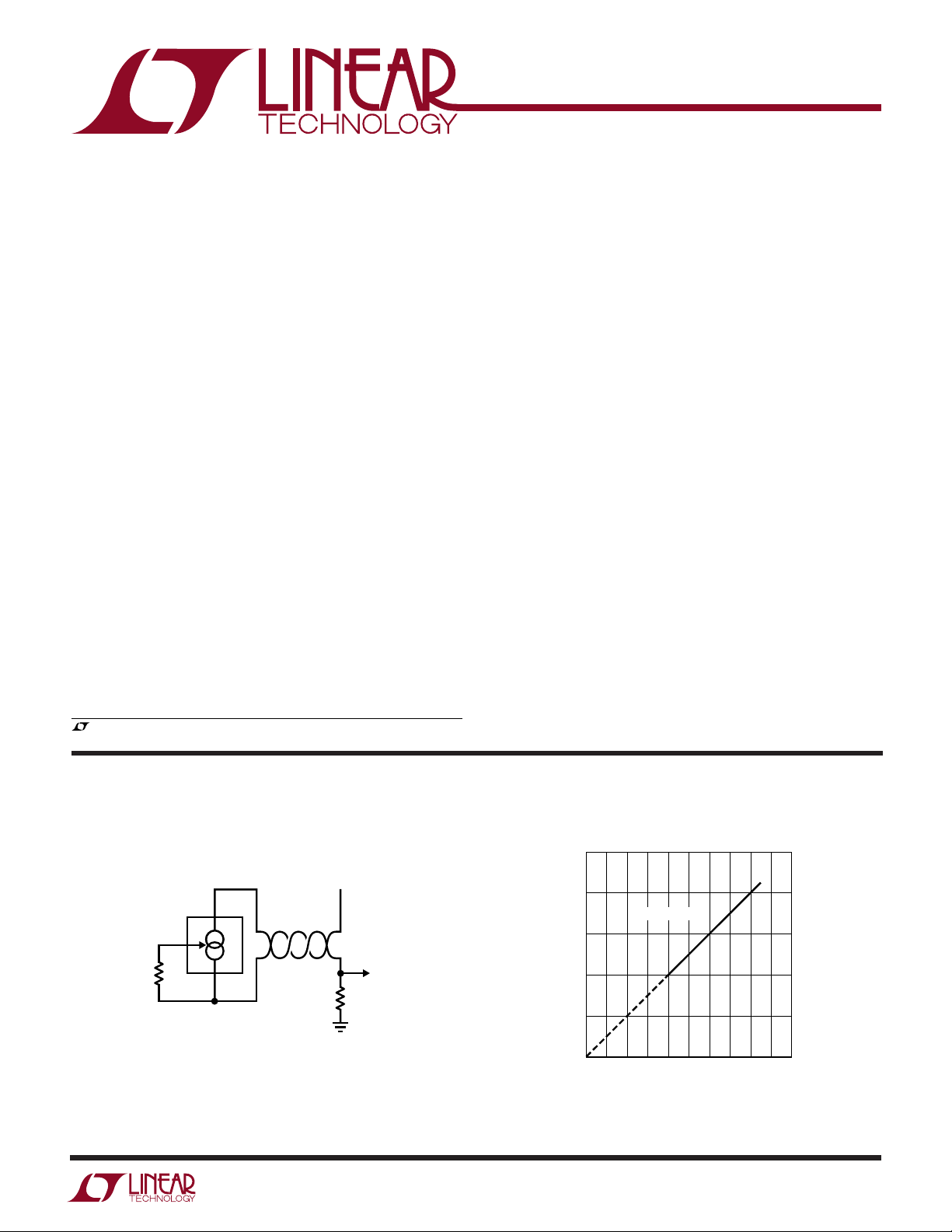
Remote Temperature Sensor with Voltage Output
≥ 5V
V
IN
+
V
R
R
SET
226Ω
LM234-3
–
V
R1
10k
10mV/°K
TA01a
If a zero temperature coefficient current source is required, this is easily achieved by adding a diode and a
resistor.
Operating Current vs Temperature
TA01b
500
225
125
TEMPERATURE (°C)
25
–75
–175
–275
500
400
R
= 226Ω
SET
300
200
TEMPERATURE (°K)
100
0
100
0
OPERATING CURRENT (µA)
200
300
400
1
LM134 Series
WW
W
ABSOLUTE AXI U RATI GS
U
(Note 1)
V+ to V– Forward Voltage
LM134 ................................................................. 40V
LM134-3/LM134-6/LM234-3/
LM234-6/LM334 ................................................. 30V
V+ to V– Reverse Voltage ........................................ 20V
R Pin to V– Voltage.................................................... 5V
Set Current ........................................................... 10mA
UUW
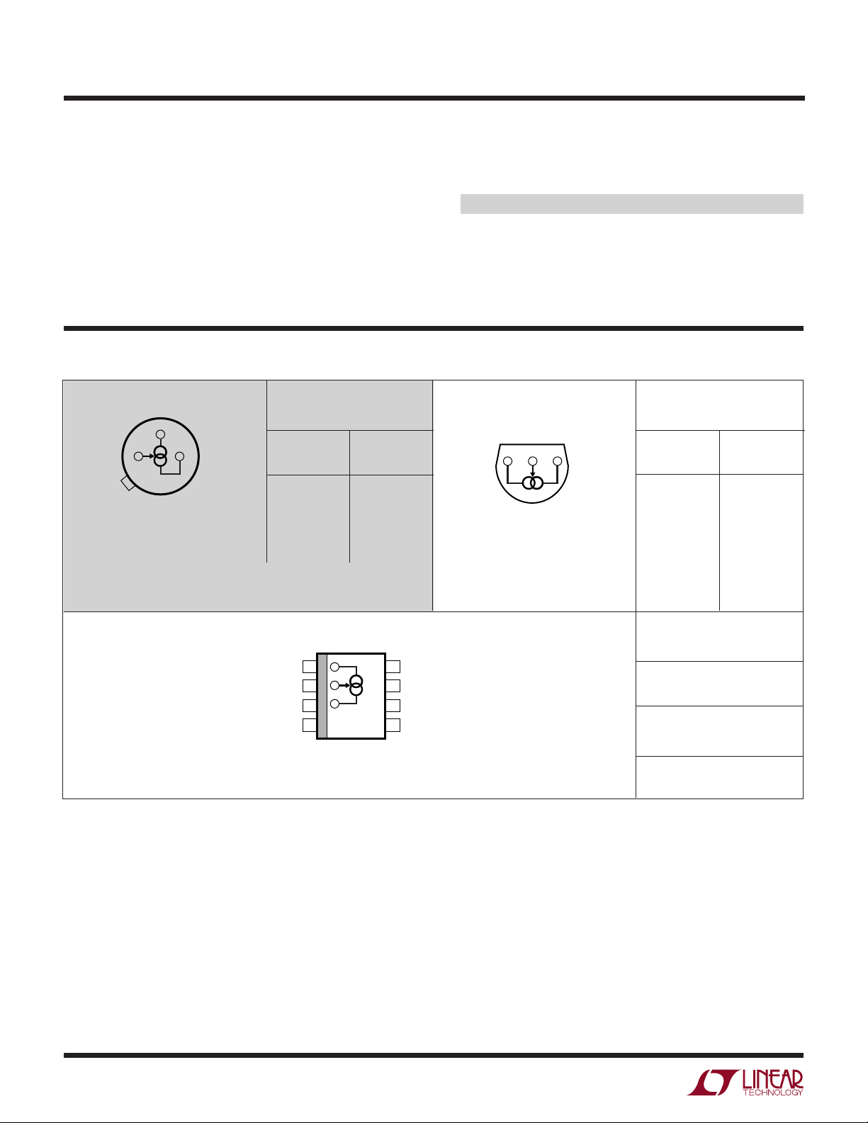
PACKAGE/ORDER I FOR ATIO
BOTTOM VIEW
+
V
–
V
R
H PACKAGE
3-LEAD TO-46 METAL CAN
T
= 150°C, θJA = 440°C/W, θJA = 80°C/W
JMAX
ORDER PART
NUMBER
CURRENT
SOURCE
LM134H
LM334H
TEMP
SENSOR
LM134H-3
LM234H-3
LM134H-6
LM234H-6
Power Dissipation.............................................. 200mW
Operating Temperature Range
LM134 (OBSOLETE) ................... –55°C to 125°C
LM234-3/LM234-6 ............................–25°C to 100°C
LM334 ..................................................... 0°C to 70°C
Storage Temperature Range ................. – 65°C to 150°C
Lead Temperature (Soldering, 10 sec).................. 300°C
ORDER PART
BOTTOM VIEW
+
V
Z PACKAGE
3-LEAD PLASTIC TO-92
T
= 100°C, θJA = 160°C/W
JMAX
V
R
–
CURRENT
LM334Z
NUMBER
SOURCE
TEMP
SENSOR
LM234Z-3
LM234Z-6
OBSOLETE PACKAGE
Consider the S8 or Z Packages for Alternate Source
–
V
1
R
2
+
V
3
NC
4
S8 PACKAGE
8-LEAD PLASTIC SO
= 100°C, θJA = 180°C/W
T
JMAX
Consult LTC Marketing for availability of LM234Z-3 and LM234Z-6
ORDER PART
NUMBER
NC
8
NC
7
NC
6
NC
5
LM334S8
S8 PART
MARKING
334
2

LM134 Series
ELECTRICAL CHARACTERISTICS
CURRENT SOURCE (Note 2)
LM134 LM334
SYMBOL PARAMETER CONDITIONS MIN TYP MAX MIN TYP MAX UNITS
∆I
V
∆I
∆V
C
SET
MIN
SET
IN
S
Set Current Error, V+ = 2.5V 10µA ≤ I
(Note 3) 1mA < I
2µA ≤ I
Ratio of Set Current to 10µA ≤ I
–
Current 1mA ≤ I
V
2µA ≤ I
Minimum Operating Voltage 2µA ≤ I
100µA < I
1mA < I
≤ 1mA 3 6 %
SET
≤ 5mA 5 8 %
SET
< 10µA812%
SET
≤ 1mA 141823141826
SET
≤ 5mA 14 14
SET
≤ 10µA 1823 1826
SET
≤ 100µA 0.8 0.8 V
SET
≤ 1mA 0.9 0.9 V
SET
≤ 5mA 1.0 1.0 V
SET
Average Change in Set Current 1.5V ≤ V+ ≤ 5V 0.02 0.05 0.02 0.1 %/V
with Input Voltage 2µA ≤ I
5V ≤ V
+
SET
≤ V
≤ 1mA
(Note 5) 0.01 0.03 0.01 0.05 %/V
MAX
1.5V ≤ V ≤ 5V 0.03 0.03 %/V
1mA < I
5V ≤ V ≤ V
Temperature Dependence of 25µA ≤ I
≤ 5mA
SET
(Note 5) 0.02 0.02 %/V
MAX
≤ 1mA 0.96 1.04 0.96 1.04
SET
Set Current (Note 4)
Effective Shunt Capacitance 15 15 pF
TEMPERATURE SENSOR (Note 2)
LM134-3,LM234-3 LM134-6, LM234-6
SYMBOL PARAMETER CONDITIONS MIN TYP MAX MIN TYP MAX UNITS
∆I
SET
V
MIN
∆I
SET
∆V
IN
C
S
Note 1: Absolute Maximum Ratings are those values beyond which the life
of a device may be impaired.
Note 2: Unless otherwise specified, tests are performed at T
pulse testing so that junction temperature does not change during test.
Note 3: Set current is the current flowing into the V
by the following formula: I
Set Current Error, V+ = 2.5V 100µA ≤ I
(Note 3) T
= 25°C
j
≤ 1mA ±1 ±2%
SET
Equivalent Temperature Error ±3 ±6 °C
Ratio of Set Current to 100µA ≤ I
–
Current
V
Minimum Operating Voltage 100µA ≤ I
≤ 1mA 141826141826
SET
≤ 1mA 0.9 0.9 V
SET
Average Change in Set Current 1.5V ≤ V+ ≤ 5V 0.02 0.05 0.02 0.1 %/V
with Input Voltage 100µA ≤ I
5V ≤ V
Temperature Dependence of 100µA ≤ I
≤ 1mA
SET
+
≤ 30V 0.01 0.03 0.01 0.05 %/V
≤ 1mA 0.98 1.02 0.97 1.03
SET
Set Current (Note 4)
Equivalent Slope Error ±2 ±3%
Effective Shunt Capacitance 15 15 pF
= 67.7mV/R
SET
= 25°C with
j
+
pin. It is determined
(at 25°C). Set current error
SET
is expressed as a percent deviation from this amount. I
0.336%/°C at T
Note 4: I
(°K). I
SET
where I
Note 5: V
= 25°C.
j
is nominally directly proportional to absolute temperature
SET
at any temperature can be calculated from: I
is I
measured at TO (°K).
O
SET
= 40V for LM134 and 30V for other grades.
MAX
increases at
SET
= IO (T/TO)
SET
3
LM134 Series
UW
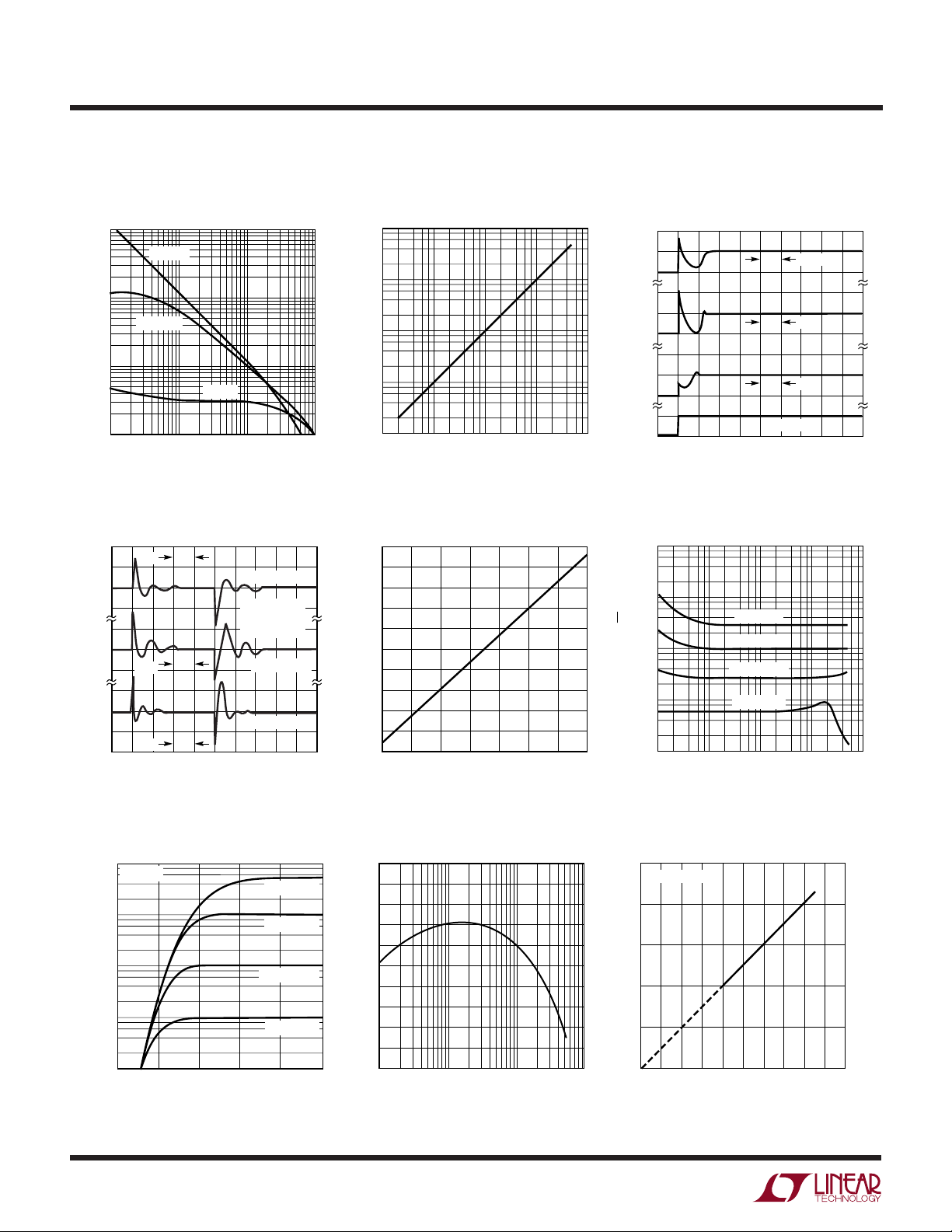
TYPICAL PERFOR A CE CHARACTERISTICS
Maximum Slew Rate for
Output Impedance
9
10
I = 10µA
8
10
I = 100µA
7
IMPEDANCE (Ω)
10
6
10
10
I = 1mA
100 1k 10k
FREQUENCY (Hz)
134 G01
Linear Operation
10
1.0
0.1
SLEW RATE (V/µs)
0.01
0.001
1 100 1000
10
I
SET
(µA)
134 G02
10000
Start-Up
10µA
0µA
100µA
0µA
SET
I
1mA
0mA
5V
0V
(*NOTE SCALE CHANGES FOR EACH CURRENT LEVEL)
TIME
200µs
50µs
5µs
INPUT
134 G03
Transient Response
2
2µs
1
0
–1
5
(%)
0
SET
∆I
10µs
–5
10
0
–10
50µs
–20
(*NOTE SCALE CHANGES FOR EACH CURRENT LEVEL)
TIME
I
= 1mA
SET
V+ TO V– = 5V
∆V = 0.4V
t
= 500ns
r, f
I
= 100µA
SET
I
= 10µA
SET
Turn-On Voltage
10mA
Tj = 25°C
1mA
100µA
SET
I
10µA
1µA
0.6
0.4 0.8 1.21.0
V+ TO V– VOLTAGE
R
R
R
R
SET
SET
SET
SET
= 680Ω
134 G04
= 14Ω
= 68Ω
= 6.8k
134 G02
1.4
Voltage Across R
86
82
78
74
70
66
62
VOLTAGE (mV)
58
54
50
46
–50
–25
Ratio of I
21
20
19
18
17
16
RATIO
15
14
13
12
11
10µA
SET
0
TEMPERATURE (°C)
to V– Current
SET
100µA 1mA 10mA
I
SET
75
50
25
100
1314/15 G01
134 G08
125
Current Noise
10k
1k
100
CURRENT (pA/√Hz)
10
1
10 1k 10k
100
FREQUENCY (Hz)
Operating Current vs
Temperature
500
R
= 226Ω
SET
400
300
200
TEMPERATURE (°K)
100
0
100
0
200
OPERATING CURRENT (µA)
I
SET
I
SET
I
SET
I
SET
= 5mA
= 1mA
= 100µA
= 10µA
300
400
134 G09
134 G06
500
100k
225
125
TEMPERATURE (°C)
25
–75
–175
–275
4

LM134 Series
U
WUU
APPLICATIO S I FOR ATIO
Basic Theory of Operation
The equivalent circuit of the LM134 is shown in Figure 1.
A reference voltage of 64mV is applied to the minus input
of A1 with respect to the V– pin. A1 serves the drive to Q2
to keep the R pin at 64mV, independent of the value of
R
. Transistor Q1 is matched to Q2 at a 17:1 ratio so that
SET
the current flowing out of the V– pin is always 1/18 of the
total current into the V+ pin. This total current is called I
and is equal to:
64 181767 7mV
R
SET SET
=
mV
.
R
A1
Figure 1.
+
–
64mV
+
V
I
SET
Q2Q1
R
R
+
SET
–
–
V
134 F01
The 67.7mV equivalent reference voltage is directly proportional to absolute temperature in degrees Kelvin (see
curve, “Operating Current vs Temperature”). This means
that the reference voltage can be plotted as a straight line
going from 0mV at absolute zero temperature to 67.7mV
at 298°K (25°C). The slope of this line is 67.7mV/298 =
227µV/°C.
The accuracy of the device is specified as a percent error
at room temperature, or in the case of the -3 and -6
devices, as both a percent error and an equivalent temperature error. The LM134 operating current changes at a
percent rate equal to (100)(227µV/°C)/(67.7mV) = 0.336%/
°C at 25°C, so each 1% operating current error is equivalent to ≈3°C temperature error when the device is used as
a temperature sensor. The slope accuracy (temperature
coefficient) of the LM134 is expressed as a ratio compared to unity. The LM134-3, for instance, is specified at
0.98 to 1.02, indicating that the maximum slope error of
SET
the device is ±2% when the room temperature current is
set to the exact desired value.
Supply Voltage Slew Rate
At slew rates above a given threshold (see curve), the
LM134 may exhibit nonlinear current shifts. The slewing
rate at which this occurs is directly proportional to I
I
= 10µA, maximum dv/dt is 0.01V/µs; at I
SET
SET
. At
SET
= 1mA,
the limits is 1V/µs. Slew rates above the limit do not harm
the LM134, or cause large currents to flow.
Thermal Effects
Internal heating can have a significant effect on current
regulation for I
1V increase across the LM134 at I
greater than 100µA. For example, each
SET
= 1mA will increase
SET
junction temperature by ≈0.4°C in still air. Output current
(I
) has a temperature coefficient of ≈0.33%/°C, so the
SET
change in current due to temperature rise will be (0.4)(0.33)
= 0.132%. This is a 10:1 degradation in regulation compared to true electrical effects. Thermal effects, therefore,
must be taken into account when DC regulation is critical
and I
exceeds 100µA. Heat sinking of the TO-46 pack-
SET
age or the TO-92 leads can reduce this effect by more than
3:1.
Shunt Capacitance
In certain applications, the 15pF shunt capacitance of the
LM134 may have to be reduced, either because of loading
problems or because it limits the AC output impedance of
the current source. This can be easily accomplished by
buffering the LM134 with a FET, as shown in the applications. This can reduce capacitance to less than 3pF and
improve regulation by at least an order of magnitude. DC
characteristics (with the exception of minimum input
voltage) are not affected.
Noise
Current noise generated by the LM134 is approximately 4
times the shot noise of a transistor. If the LM134 is used
as an active load for a transistor amplifier, input referred
noise will be increased by about 12dB. In many cases, this
is acceptable and a single stage amplifier can be built with
a voltage gain exceeding 2000.
5

LM134 Series
U
WUU
APPLICATIO S I FOR ATIO
Lead Resistance
The sense voltage which determines the operating current
of the LM134 is less than 100mV. At this level, thermocouple or lead resistance effects should be minimized by
locating the current setting resistor physically close to the
device. Sockets should be avoided if possible. It takes only
0.7Ω contact resistance to reduce output current by 1% at
the 1mA level.
Start-Up Time
The LM134 is designed to operate at currents as low as
1µA. This requires that internal biasing current be well
below that level because the device achieves its wide
operating current range by using part of the operating
current as bias current for the internal circuitry. To ensure
start-up, however, a fixed trickle current must be provided
internally. This is typically in the range of 20nA to 200nA
and is provided by the special ultralow I
the Schematic Diagrams as Q7 and Q8. The start-up time
of the LM134 is determined by the I
DSS
the capacitor C1. This capacitor must charge to approximately 500mV before Q3 turns on to start normal circuit
operation. This takes as long as (500mV)(50pF)/(20nA) =
1.25ms for very low I
DSS
values.
Using the LM134 as a Temperature Sensor
Because it has a highly linear output characteristic, the
LM134 makes a good temperature sensor. It is particularly
useful in remote sensing applications because it is a
current output device and is therefore not affected by long
wire runs. It is easy to calibrate, has good long term
stability and can be interfaced directly with most data
acquisition systems, eliminating the expensive preamplifiers required for thermocouples and platinum sensors.
A typical temperature sensor application is shown in
Figure␣ 2. The LM134 operating current at 25°C is set at
298µA by the 226Ω resistor, giving an output of 1µA/°K.
The current flows through the twisted pair sensor leads to
the 10k termination resistor, which converts the current
output to a voltage of 10mV/°K referred to ground. The
FETs shown in
DDS
of these FETs and
voltage across the 10k resistor will be 2.98V at 25°C, with
a slope of 10mV/°C. The simplest way to convert this
signal to a Centigrade scale is to subtract a constant 2.73V
in software. Alternately, a hardware conversion can be
used, as shown in Figure 3, using an LT1009 as a level
shifter to offset the output to a Centigrade scale.
The resistor (R
) used to set the operating current of the
SET
LM134 in temperature sensing applications should have
low temperature coefficient and good long term stability.
A 30ppm/°C drift in the resistor will change the slope of the
temperature sensor by 1%, assuming that the resistor is
at the same temperature as the sensor, which is usually the
case since the resistor should be located physically close
to the LM134 to prevent errors due to wire resistance. A
long term shift of 0.3% in the resistor will create a 1°C
temperature error. The long term drift of the LM134 is
typically much better than this, so stable resistors must be
used for best long term performance.
Calibration of the LM134 as a temperature sensor is
extremely easy. Referring to Figure 2, calibration is achieved
by trimming the termination resistor.
This theoretically
trims both zero and slope simultaneously for Centigrade
and Fahrenheit applications.
The initial errors in the LM134
are directly proportional to absolute temperature, just like
the actual output. This allows the sensor to be trimmed at
any temperature and have the slope error be corrected at
the same time. Residual slope error is typically less than
1% after this single trim is completed.
VS ≥ 5V
+
V
LM234-3
R
TO DATA
ACQUISITION
SYSTEM
10mV/°K
CALIBRATE
–
V
9.53k
Figure 2 Kelvin Temperature Sensor
I = 1µA/°K
1k
R
SET
226Ω
134 F02
6

LM134 Series
U
WUU
APPLICATIO S I FOR ATIO
The two trims shown in Figure 3 are still intended to be a
“one point” temperature calibration, where the zero and
the slope are trimmed at a single temperature. The LT1009
reference is adjusted to give 2.700V at node “a” at T
= 25°C. The 1k trimmer then adjusts the output for 0.25V,
completing the calibration. If the calibration is to be done
at a temperature other than 25°C , trim the LT1009 for
2.7025—(1µA)[T
SENSOR
(°C)](100Ω) at node “a”, then
adjust the 1k trimmer for proper output.
≥ 4V
V
S
+
V
LM134-3
R
OUTPUT
10mV/°C
“a”
–15V
9.53k
1%
1k
SLOPE
ADJ
100Ω
10k
LT1009
10k
ZERO
ADJ
–
V
R
SET
226Ω
134 F03
SENSOR
If higher accuracy is required, a two point calibration
technique can be used. In Figure 4, separate zero and slope
trims are provided. Residual nonlinearity is now the limitation on accuracy. Nonlinearity of the LM134 in a 100°C
span is typically less than 0.5°C. This particular method of
trimming has the advantage that the slope trim does not
interact with the zero trim. Trim procedure is to adjust for
zero output with T
SENSOR
= 0°C, then trim slope for proper
output at some convenient second temperature. No further trimming is required.
+
≥ 5V
V
+
LM134-3
226Ω*
*LOW TC, STABLE RESISTOR
V
R
1%
OUTPUT
10mV/°C
ZERO
TRIM
10k
134 F04
–
V
SLOPE
TRIM
500k
50k
–15V
332k1%11k*
15k
LT1009
Figure 3. Centigrade Temperature Sensor
TYPICAL APPLICATIO S
Basic 2-Terminal
Current Source
V
IN
+
V
I
SET
LM334
R
R
–
V
–V
IN
SET
134 TA02
Figure 4. Centigrade Temperature Sensor with 2 Point Trim
U
Low Output Impedance
Thermometer (Kelvin Output)
V
≥ 4.8V
IN
+
V
LM334
0.1µF
*OUTPUT IMPEDANCE OF THE LM134 AT THE “R” PIN IS
APPROXIMATELY Ω, WHERE R
EXTERNAL RESISTANCE CONNECTED TO THE V
NEGATIVE RESISTANCE CAN BE REDUCED BY A FACTOR OF
5 OR MORE BY INSERTING AN EQUIVALENT RESISTOR IN
SERIES WITH THE OUTPUT.
–
V
C1
–R
O
16
R3*
600Ω
R
R1
230Ω
1%
R2
10k
1%
O
V
OUT
Z
OUT
IS THE EQUIVALENT
= 10mV/°K
≤ 100Ω
134 TA03
–
PIN. THIS
Zero Temperature
Coefficient Current Source
V
IN
+
I
+
V
R
LM334
1N457
*SELECT RATIO OF R1 TO R
OBTAIN ZERO DRIFT. I
–
V
R
SET
D1
–V
IN
R1*
≈10 R
134 TA04
+
≈2 I
SET
SET
SET
TO
.
7

LM134 Series
TYPICAL APPLICATIO S
U
Higher Output Current
V
IN
R1*
+
V
LM334
*SELECT R1 AND C1 FOR OPTIMUM STABILITY
–
V
2N2905
C1*
R
R
SET
–V
TA05
IN
Micropower Bias
V
IN
LM4250
1µA
+
LM334
V
–
V
R
SET
68k
R
–V
IN
TA08
Low Output Impedance Thermometer
V
IN
C1
0.0022
LM334
R1
15k
V
V
+
–
R2
300Ω
2N4250
V
= 10mV/°K
OUT
≤ 2Ω
R
Z
R3
100Ω
R4
4.5k
OUT
1.2V Regulator with 1.8V Minimum Input
100k
C1
0.001
+
V
LM134**
*
SELECT RATIO OF R1 TO R2 FOR ZERO TEMPERATURE DRIFT
**
LM134 AND DIODE SHOULD BE ISOTHERMAL
R
–
V
2N4250
R1
33k
TA06
VIN ≥ 1.8V
V
OUT
I
OUT
1N457**
R1*
≈6k
1%
R2*
680Ω
1%
V
≥ V
IN
= 1.2V
≤ 200µA
TA09
Low Input Voltage Reference Driver
+ 200mV
REF
R1
1.5k
C1
LM334
0.1
+
V
–
V
Q1
2N4250
V
= VZ + 64mV AT 25°C
OUT
≤ 3mA
I
+
V
Z
–
R
LT1009
R2
120Ω
OUT
Zener Biasing
V
IN
+
V
LM334
R
–
V
V
Z
TA10
TA07
R
SET
V
OUT
Alternate Trimming Technique
V
IN
+
V
R
–
R1*
V
–V
IN
LM334
*FOR ±10% ADJUSTMENT, SELECT R
10% HIGH AND MAKE R1 ≈ 3R
8
Buffer for Photoconductive Cell
+
V
LM334
R
SET
TA11
1.5V
R
–
V
TA12
High Precision Low TC Current Source
+
I
≥ 50µA
SET
+
V
LM334
V
LT1004-1.2
(1.235V)
R
–
R1
6.8k
R2*
TA13
–
SET
SET
1.37V
*I
= + 10µA
SET
R2
TC = 0.016%/°C + 33nA/°C
I
SET
REGULATION ≈ 0.001%/V

TYPICAL APPLICATIO S
LM134 Series
U
Precision 10nA Current Source
15V
+
V
–
V
LT1004-1.2
2
–
3
+
–15V
R
R1
2.7k
15V
LT1008
4
7
LM134
R2
226k
R3
1M
R4
100MΩ
I
O
= 10nA
I
O
Z
≥ 1012Ω
O
COMPLIANCE = –14V TO 12.5V
8
6
200pF
LM334
LT1004-1.2
(1.235V)
BUFFERED
VOLTAGE
OUTPUT
TA14
FET Cascoding for Low Capacitance
and/or Ultrahigh Output Impedance
V
IN
I
SET
Q1*
+
V
LM334
R
V
IN
+
V
–
V
LM334
R
Micropower 5V Reference
V
R
5.6k
+
LM4250
–
4
7
22M
3
2
1M
1%
R
SET
= 6.5V TO 15V
IN
6
8
150pF
V
OUT
3.01M
1%
= 5V
TA15
W
SCHE ATIC DIAGRA
R
SET
–
V
–V
*SELECT Q1 OR Q2 TO ENSURE AT LEAST 1V
IN
ACROSS THE LM134. V
(1 – I
P
W
Q7 Q8
Q3
Q2
C1
50pF
SET/IDSS
Q5Q4
–V
Q2*
I
SET
IN
) ≥ 1.2V.
Q1
+
V
Q6
134 SD
TA16
R
–
V
9

LM134 Series
PACKAGE DESCRIPTIO
U
H Package
2-Lead and 3-Lead TO-46 Metal Can
(Reference LTC DWG # 05-08-1340)
REFERENCE
PLANE
0.209 – 0.219
(5.309 – 5.537)
0.178 – 0.195
(4.521 – 4.953)
0.500
(12.700)
0.016 – 0.021**
(0.406 – 0.533)
DIA
± 0.005
0.060
(1.524± 0.127)
DIA
0.180 ± 0.005
(4.572 ± 0.127)
MIN
0.085 – 0.105
(2.159 – 2.667)
*
0.025
(0.635)
MAX
0.050
(1.270)
0.036 – 0.046
(0.914 – 1.168)
*
LEAD DIAMETER IS UNCONTROLLED BETWEEN THE REFERENCE PLANE
AND 0.045" BELOW THE REFERENCE PLANE
**
FOR SOLDER DIP LEAD FINISH, LEAD DIAMETER IS
TYP
0.100
(2.540)
TYP
PIN 1
45°
OBSOLETE PACKAGE
Z Package
3-Lead Plastic TO-92 (Similar to TO-226)
(Reference LTC DWG # 05-08-1410)
0.180 ± 0.005
(4.572 ± 0.127)
0.90
(2.286)
NOM
0.050
(1.270)
TYP
FOR 3-LEAD PACKAGE ONLY
0.028 – 0.048
(0.711 – 1.219)
H02/03(TO-46) 1098
0.016 – 0.024
(0.406 – 0.610)
10
0.500
(12.70)
MIN
0.050
(1.27)
BSC
10° NOM
0.050
UNCONTROLLED
LEAD DIMENSION
(1.270)
MAX
0.016 ± 0.003
(0.406 ± 0.076)
0.060 ± 0.010
(1.524 ± 0.254)
0.140 ± 0.010
(3.556 ± 0.127)
5°
NOM
0.015 ± 0.002
(0.381 ± 0.051)
0.098 +016/–0.04
(2.5 +0.4/–0.1)
2 PLCS
TO-92 TAPE AND REEL
REFER TO TAPE AND REEL SECTION OF
LTC DATA BOOK FOR ADDITIONAL INFORMATION
Z3 (TO-92) 0401

PACKAGE DESCRIPTIO
U
S8 Package
8-Lead Plastic Small Outline (Narrow .150 Inch)
(Reference LTC DWG # 05-08-1610)
0.189 – 0.197*
(4.801 – 5.004)
7
8
6
LM134 Series
5
0.228 – 0.244
(5.791 – 6.197)
0.010 – 0.020
(0.254 – 0.508)
0.008 – 0.010
(0.203 – 0.254)
*
DIMENSION DOES NOT INCLUDE MOLD FLASH. MOLD FLASH
SHALL NOT EXCEED 0.006" (0.152mm) PER SIDE
**
DIMENSION DOES NOT INCLUDE INTERLEAD FLASH. INTERLEAD
FLASH SHALL NOT EXCEED 0.010" (0.254mm) PER SIDE
× 45°
0°– 8° TYP
0.016 – 0.050
(0.406 – 1.270)
0.053 – 0.069
(1.346 – 1.752)
0.014 – 0.019
(0.355 – 0.483)
TYP
0.150 – 0.157**
(3.810 – 3.988)
SO8 1298
1
3
2
4
0.004 – 0.010
(0.101 – 0.254)
0.050
(1.270)
BSC
Information furnished by Linear Technology Corporation is believed to be accurate and reliable.
However, no responsibility is assumed for its use. Linear Technology Corporation makes no representation that the interconnection of its circuits as described herein will not infringe on existing patent rights.
11

LM134 Series
TYPICAL APPLICATIO S
In-Line Current Limiter Generating Negative Output Impedance
R
SET
R
+
V
V
IN
LM334
–
V
OP AMP
U
C1*
LM334
V
IN
+
V
–
V
R1*
R
R
SET
*USE MINIMUM VALUE REQUIRED TO
ENSURE STABILITY OF PROTECTED
DEVICE. THIS MINIMIZES INRUSH
CURRENT TO A DIRECT SHORT.
TA17
*Z
OUT
Ground Referred Fahrenheit Thermometer
V
≥ 3V
IN
R4
56k
2N4250
LM334
*SELECT R3 = V
**SELECT FOR 1.2mA
C1
0.01
+
V
–
V
R1
8.25k
1%
R
R2
100Ω
1%
REF
R3*
/583µA
V
= 10mV/°F
OUT
10°F ≤ T ≤ 250°F
V
IN
R5**
LT1009
2.5V*
TA19
–V
IN
≈ –16 • R1(R1/VIN MUST NOT EXCEED I
TA18
SET
).
12
Linear Technology Corporation
1630 McCarthy Blvd., Milpitas, CA 95035-7417
(408) 432-1900 ● FAX: (408) 434-0507
●
www.linear.com
134sc LT/CP 1001 1.5K REV C • PRINTED IN USA
LINEAR TECHNOLOGY CORPORATION 1991
 Loading...