

Page 1
DEMO MANUAL DC571A
LTC2418
8-/16-Channel Differential
DESCRIPTION
The LTC®2418 is a high resolution, 24-bit ΔΣ ADC with
5ppm INL and 5μV offset. Channel selection is programmed
through a simple serial interface. Since there is no latency,
each conversion is valid, even after a change in input
channel.
DC571A is a member of Linear Technology‘s QuikEval™
family of demonstration boards.
It is designed to allow easy evaluation of the LTC2418 and
may be connected directly to the target application’s analog
QUICK START PROCEDURE
Connect DC571 to DC590 USB serial controller using the
supplied 14-conductor ribbon cable. Connect DC590 to
host PC with a standard USB A/B cable. Run the evaluation software supplied with DC590 or downloaded from
www.linear.com/software. The correct program will be
loaded automatically.
24-Bit
signals while using the DC590 USB serial controller board
and supplied software to measure performance.
After evaluating with LTC’s software, the digital signals can
be connected to the application’s processor/controller for
development of the serial interface.
Design files for this circuit board are available at
www.linear.com/demo
http://
L, LT, LTC, LTM, Linear Technology and the Linear logo are registered trademarks and
QuikEval is a trademark of Linear Technology Corporation. All other trademarks are the property
of their respective owners.
∆Σ ADC
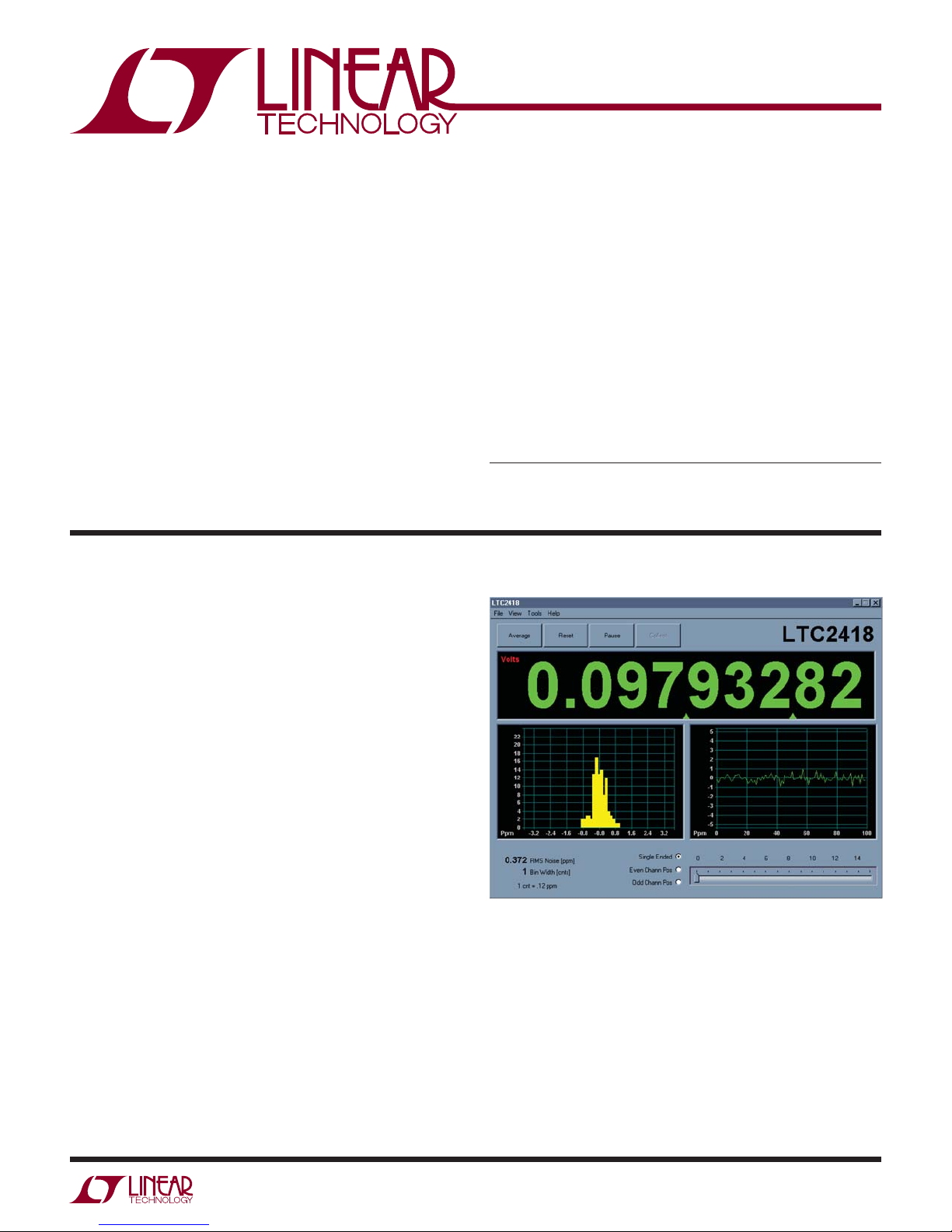
Click the COLLECT button to start reading the input voltage.
Click the slider at the bottom of the strip-chart display to
change the input channel being displayed. For differential
measurements, Even channel pos and odd channel pos
correspond to even channels being positive inputs or
odd channels being positive inputs, respectively. See the
LTC2418 data sheet for details of channel selection.
Tools are available for logging data, changing reference
voltage, changing the number of points in the strip-chart
and histogram, and changing the number of points averaged for the DVM display.
Figure 1. DC590 Program
dc571af
1
Page 2

DEMO MANUAL DC571A
HARDWARE SETUP
JUMPERS
JP1: Select the connection for the common pin, either
ground or external connection. Single-ended measurements are taken with respect to this pin.
JP2 and JP3: Select the source for differential reference.
Selecting 5V and GND will use the onboard 5V reference.
Select EXT to use an external reference.
JP5: Select notch frequency, 60Hz or 50Hz. Alternatively,
this jumper may be removed and an external conversion
clock applied to the center pin of JP5.
EXPERIMENTS
Figure 2 shows a number of applications for the LTC2418.
CH0, CH1, CH2
Channels 0 and 1 measure the differential output of an
Intersema MS5401 absolute pressure sensor. The 6.8k
resistor performs a first order temperature compensation
of the bridge output. CH2 measures the bridge voltage,
which provides a convenient temperature measurement.
This can also be used to perform further temperature
compensation in software.
CH3
Channel 3 measures the output of a thermistor in a half
bridge circuit. Many thermistors will work, the constraints
are that the bridge output must have an impedance of
less than 20k and the voltage must not go above V
CH4
Channel 4 measures the output of a type J thermocouple.
The circuit shown for channel 3 can be used for cold junction compensation. The cold junction sensor should be
close to the connections of the thermocouple to the board.
CH5
REF
/2.
CONNECTION TO DC590 SERIAL CONTROLLER
J1 is the power and digital interface connector. Connect
to DC590 serial controller with supplied 14-conductor
ribbon cable.
ANALOG CONNECTIONS
Analog signal connections are made via the turret posts
along the edge of the board (CH0 to CH15.) Also, if you are
connecting the board to an existing circuit, make full use
of the four ground connections at the corners of the board.
CH7
Channel 7 measures the output of a resistive attenuator.
CH8, CH9
Channels 8 and 9 measure the drop across a Deltec SWE3000-50 current shunt. Up to 3000A can be measured,
with a resolution of 60mA. With careful grounding, both
positive and negative currents can be measured. Care
must be taken to ensure that both inputs stay more positive than GND–0.3V.
CH10
Channel 10 is buffered with an LT1793 FET input amplifier
suitable for very high source impedance measurements.
CH11
Channel 11 measures the output of a precision rectifier.
CH12, CH13
Channels 12 and 13 measure a 3-wire RTD. The differential
voltage is the output, and CH12 single-ended reading is
the ground lead compensation.
Channel 5 measures the output of an Omega OS36-01
infrared thermocouple. This can be used for remote temperature measurement.
CH6
Channel 6 measures the photocurrent of a Hamamatsu
S1336-5BK photodiode.
2
CH14, CH15
Channels 14 and 15 measure the output of a 350Ω bridge.
This is standard for a wide variety of sensors. Typically
the full-scale output voltage is only 10mV. However, the
LTC2418 still gives 13 effective bits of resolution with no
amplification.
dc571af
Page 3

EXPERIMENTS
DEMO MANUAL DC571A
Figure 2. LTC2418 Applications
dc571af
3
Page 4

DEMO MANUAL DC571A
PARTS LIST
ITEM QTY REFERENCE PART DESCRIPTION MANUFACTURER/PART NUMBER
1 1 C1 CAP, X5R, 10μF 6.3V, 20%, 0805 TDK, C2012X5R0J106M
2 1 C2 CAP, X7R 0.01μF 16V 10%, 0603 AVX, 0603YC103KAT1A
3 1 C3 CAP, X5R 4.7μF 6.3V, 20%, 0805 TAIYO YUDEN, JMK212BJ475MGT
4 5 C4, C5 ,C6, C7, C8 CAP, X7R 0.1μF 16V, 0603 AVX, 0603YC104MAT1A
5 26 E1 TO E26 TESTPOINT, TURRET, 0.064" MILL-MAX, 2308-2
6 5 JP1, JP2, JP3, JP4, JP5 JMP, 3PIN 1 ROW 0.079CC COMM-CON, 2802S-03-G1
7 5 SHUNTS FOR JP1 TO JP5 SHUNT, 0.079" CENTER COMM-CON CCIJ2MM-138G
8 1 J1 HEADER, 2 x 7PIN, 0.079CC MOLEX, 87331-1420
9 0 R1 RES, 0606 OPT
10 1 R2 RES, CHIP 100 1/16W 5%, 0603 AAC, CR16-101JM
11 2 R4, R3 RES, CHIP 4.99k 1/16W 1%, 0603 AAC, CR16-4991FM
12 1 R5 RES, CHIP 10k 1/16W 5%, 0603 AAC, CR16-103JM
13 1 U1 IC, LTC2418CGN, SSOP16GN LINEAR TECHNOLOGY, LTC2418CGN
14 1 U2 IC, NC7SZ157P6X, SC70-6P FAIRCHILD SEMI, NC7SZ157P6X
15 1 U3 IC, 24LC025, TSSOP-8 MICROCHIP, 24LC025-I /ST
16 1 U4 IC, NL17SZ74US, US8 ON SEMI, NL17SZ74US
17 1 U5 IC, LT1236ACS8-5, SO8 LINEAR TECHNOLOGY, LT1236ACS8-5
4
dc571af
Page 5

SCHEMATIC DIAGRAM
J1
VCC
1
2
E15
CH3
E17
CH4
E16
CH2
CH1
E18
CH0
E26
E13
CH5
E11
CH7
E10
GND
E12
CH6
3
E14
DEMO MANUAL DC571A
A
8
5
6
OPT
5
MISO
7
8
9
6
7
MOSI
CS
C5
0.1UF
R2
100
C8
VCC
6
U2
1
342
1
342
1
SCK
VIN
FO
R1
9
U3
S
I1
0.1UF
10
10
81
VCCA0
5
VCC
GND
2
12
11
12
11
R4
4.99K
1%
R3
4.99K
1%
7
6
WP
SCL
A1A2VSS
234
4
Z
I0
NC7SZ157P6X
3
13
13
5
SDA
14
14
24LC025
VCC
HD2X7-079-MOLEX
13
NORMALTRIGGERED
2
TRIG MODE
3
5
Q
VCCGND
84
D
1
2
JP4
Q
CP
U4
CLR PR
NL17SZ74US
6 7
Fax: (408)434-0507
Milpitas, CA 95035
Phone: (408)432-1900
1630 McCarthy Blvd.
LTC Confidential-For Customer Use Only
TECHNOLOGY
KIM T.
APPROVALS
CONTRACT NO.
DRAWN:
SCHEMATIC
TITLE:
CHECKED:
APPROVED:
11
SHEET OF
1
DC571A-1 * LTC2418CGN
Thursday, January 09, 2003
DWG NO. REV
8-CHANNEL DIFFERENTIAL 24-BIT ADC
A
2
SIZE
DATE:
MARK T.
ENGINEER:
DESIGNER:
3
C6
0.1UF
C7
45
GNDTRIM
U5
VOUT
5V
13
R5
10K
E24
GND
0.1UF
2
3
NC
VIN
VOUTNCNC
678
2
EXT
JP2
REF+
1
NC
LT1236ACS8-5
4
ALL CAPACITORS ARE IN MICROFARADS, 0603.
2. INSTALL SHUNT ON JP1-JP5 PIN 1 AND 2.
1. ALL RESISTORS ARE IN OHMS, 0603.
NOTES: UNLESS OTHERWISE SPECIFIED
5
A A
2
60Hz
CH7
CH2
CH1
CH14
CH13
CH15
CH14
E7
CH13E9CH15
E8
CH14
VCC
2019181716
21
SDI
CH0
CH15
VCC
8
9
VCC
E19
VCC
2625242322
27
28
CH5
CH4
CH3
CH6
CH7
CH9
CH9
CH10
E4
D D
CH10
CH11
CH10
CH12
CH11
5
476
CH12
E5
CH11
E6
CH13
CH12
CH8
U1
4
5
123
CH9
CH8
E1
E3
GND
E2
CH8
FO
FO
COM
101112
COM
REF+
C2
0.01UF
C1
10UF,6.3V
SDO
SCK
REF+
REF-
0805
E20
CS/
15
CS
SDO
NC
REF-
13
14
GND
13
COM
COM
GND
NC
2
JP1
COM
MOSI
SCK
CH0
CH1
CH2
CH3
CH4
CH5
CH6
VCC
LTC2418CGN
EXT
REF+
E21
REF+
C C
50Hz
13
Fo
JP5
C4
0.1UF
C3
0805
4.7UF,6.3V
REF-
E22
2
GND
13
JP3
E25
GND
REF-
EXT
REF-
TRIG
E23
TRIG
B B
dc571af
Information furnished by Linear Technology Corporation is believed to be accurate and reliable.
However, no responsibility is assumed for its use. Linear Technology Corporation makes no representation that the interconnection of its circuits as described herein will not infringe on existing patent rights.
5
Page 6

DEMO MANUAL DC571A
DEMONSTRATION BOARD IMPORTANT NOTICE
Linear Technology Corporation (LTC) provides the enclosed product(s) under the following AS IS conditions:
This demonstration board (DEMO BOARD) kit being sold or provided by Linear Technology is intended for use for ENGINEERING DEVELOPMENT
OR EVALUATION PURPOSES ONLY and is not provided by LTC for commercial use. As such, the DEMO BOARD herein may not be complete
in terms of required design-, marketing-, and/or manufacturing-related protective considerations, including but not limited to product safety
measures typically found in finished commercial goods. As a prototype, this product does not fall within the scope of the European Union
directive on electromagnetic compatibility and therefore may or may not meet the technical requirements of the directive, or other regulations.
If this evaluation kit does not meet the specifications recited in the DEMO BOARD manual the kit may be returned within 30 days from the date
of delivery for a full refund. THE FOREGOING WARRANTY IS THE EXCLUSIVE WARRANTY MADE BY THE SELLER TO BUYER AND IS IN LIEU
OF ALL OTHER WARRANTIES, EXPRESSED, IMPLIED, OR STATUTORY, INCLUDING ANY WARRANTY OF MERCHANTABILITY OR FITNESS
FOR ANY PARTICULAR PURPOSE. EXCEPT TO THE EXTENT OF THIS INDEMNITY, NEITHER PARTY SHALL BE LIABLE TO THE OTHER FOR
ANY INDIRECT, SPECIAL, INCIDENTAL, OR CONSEQUENTIAL DAMAGES.
The user assumes all responsibility and liability for proper and safe handling of the goods. Further, the user releases LTC from all claims
arising from the handling or use of the goods. Due to the open construction of the product, it is the user’s responsibility to take any and all
appropriate precautions with regard to electrostatic discharge. Also be aware that the products herein may not be regulatory compliant or
agency certified (FCC, UL, CE, etc.).
No License is granted under any patent right or other intellectual property whatsoever. LTC assumes no liability for applications assistance,
customer product design, software performance, or infringement of patents or any other intellectual property rights of any kind.
LTC currently services a variety of customers for products around the world, and therefore this transaction is not exclusive.
Please read the DEMO BOARD manual prior to handling the product. Persons handling this product must have electronics training and
observe good laboratory practice standards. Common sense is encouraged.
This notice contains important safety information about temperatures and voltages. For further safety concerns, please contact a LTC application engineer.
Mailing Address:
Linear Technology
1630 McCarthy Blvd.
Milpitas, CA 95035
Copyright © 2004, Linear Technology Corporation
Linear Technology Corporation
6
1630 McCarthy Blvd., Milpitas, CA 95035-7417
(408) 432-1900 ● FAX: (408) 434-0507 ● www.linear.com
dc571af
LT 0612 • PRINTED IN USA
© LINEAR TECHNOLOGY CORPORATION 2012
 Loading...