

Page 1
LPWWS Smart Wi-Fi Wall Station
Programming / Installation Instructions
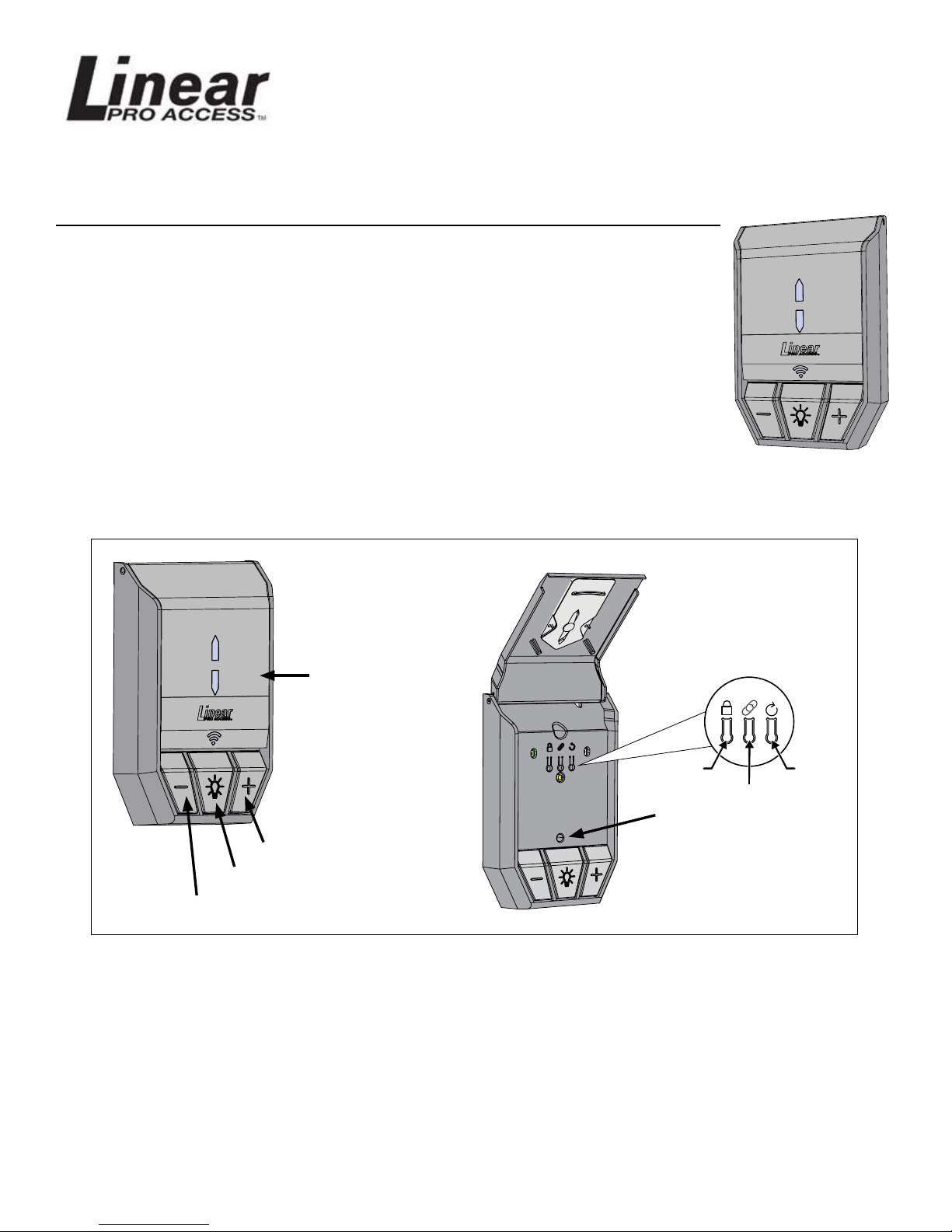
This Wall Station allows operation of the light and door using the buttons, and when
paired with the Linear PRO Access Android or iOS application you can operate garage
doors, manage your family’s access, controls lights and it informs you of people
coming and going, from any location.
Requirements
To use with the app you will need:
• a Wi-Fi network with internet connectivity
• a strong Wi-Fi signal in the garage where you are installing the wall station
• an Android or iOS smartphone or tablet.
See page 5 for instructions on downloading and installing the Linear PRO Access garage
door app.
GTO Access Systems, LLC
Manufactured by:
(844) 256-3130
www.gtoaccess.com
Wi-Fi Wall Station Functions
Press to brighten the light.
Press to turn the light on and off.
Press to dim the light.
Installing the Wi-Fi Wall Station ............................ page 2
Press to open and
close the garage door.
LOCK RESET
Wi-Fi LINK
Light indicates proper
connection with Wi-Fi
network and the secure
cloud controller (see
Page 4).
Wiring the Wall Station ........................................ page 3
Test the Wall Station ............................................ page 3
Using the Wall Station ......................................... page 4
LED Lights on the Wall Station ........................... page 5
Entrematic app Installation .................................. page 5
Troubleshooting ................................................... page 7
Printed in China for GTO Access Systems, LLC.
Copyright© 2017 GTO Access Systems, LLC
Document Number: 10016997 REV A (05-01-17)
Page 2
Installing the Wi-Fi Wall Station
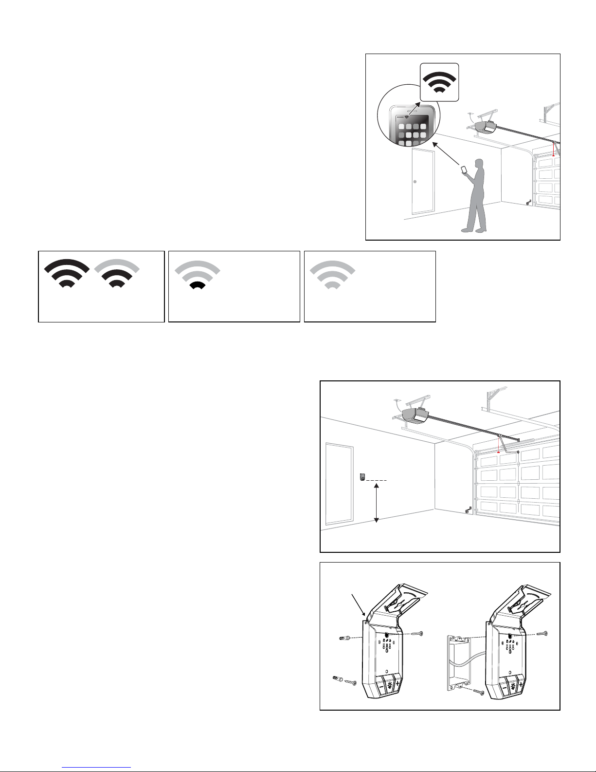
Test Wi-Fi Signal Strength
Before you afx the Wi-Fi wall station to the wall, survey
your location to check the Wi-Fi signal. To do this, take your
smart phone or tablet, connect it to your Wi-Fi network and
then place your device on the wall where you want to attach
the wall station.
If you have 2 or 3 bars on your device for the Wi-Fi network,
the signal is strong and you can proceed. If not, use one of
these options to extend your Wi-Fi network’s range.
• Move your Wi-Fi router closer to the garage.
• Purchase a Wi-Fi range extender.
Strong Wi-Fi signal
Smart Control Wall Station will
connect to your Wi-Fi network.
Weak Wi-Fi signal
Smart Control Wall Station may
not connect to your Wi-Fi network.
No Wi-Fi signal
Smart Control Wall Station will
not connect to your Wi-Fi network.
The Wi-Fi wall station must receive a strong signal from your home’s Wi-Fi router to work.
Choose Placement of Wall Station
The wall station is typically mounted inside the garage
on the wall adjacent to the door into the house. Wall
station can be mounted in any convenient place on a
drywall-covered wall with wood studs and lled with
blown-in or batt insulation.
If possible, avoid afxing the wall station:
• to solid brick or concrete walls
• to metal studs or walls with metal inside
• on top of or near AC electrical lines.
Mount Smart Control Wall Station
at least 5 feet above oor level.
Mount Wall Station
Follow the instructions in the diagram to the right.
MOUNTING TO WALL
Route wire through slot
in back of case
MOUNTING TO GANG BOX
Use machine screws when
mounting to a single
gang box
See page 5 to connect the wall station to your mobile device through the Linear Smart Control app.
LPWWS | Installation Instructions
Use wood
screws and
drywall
anchors
2
Page 3
IMPORTANT
Wire polarity is critical with the Wi-Fi
wall station.
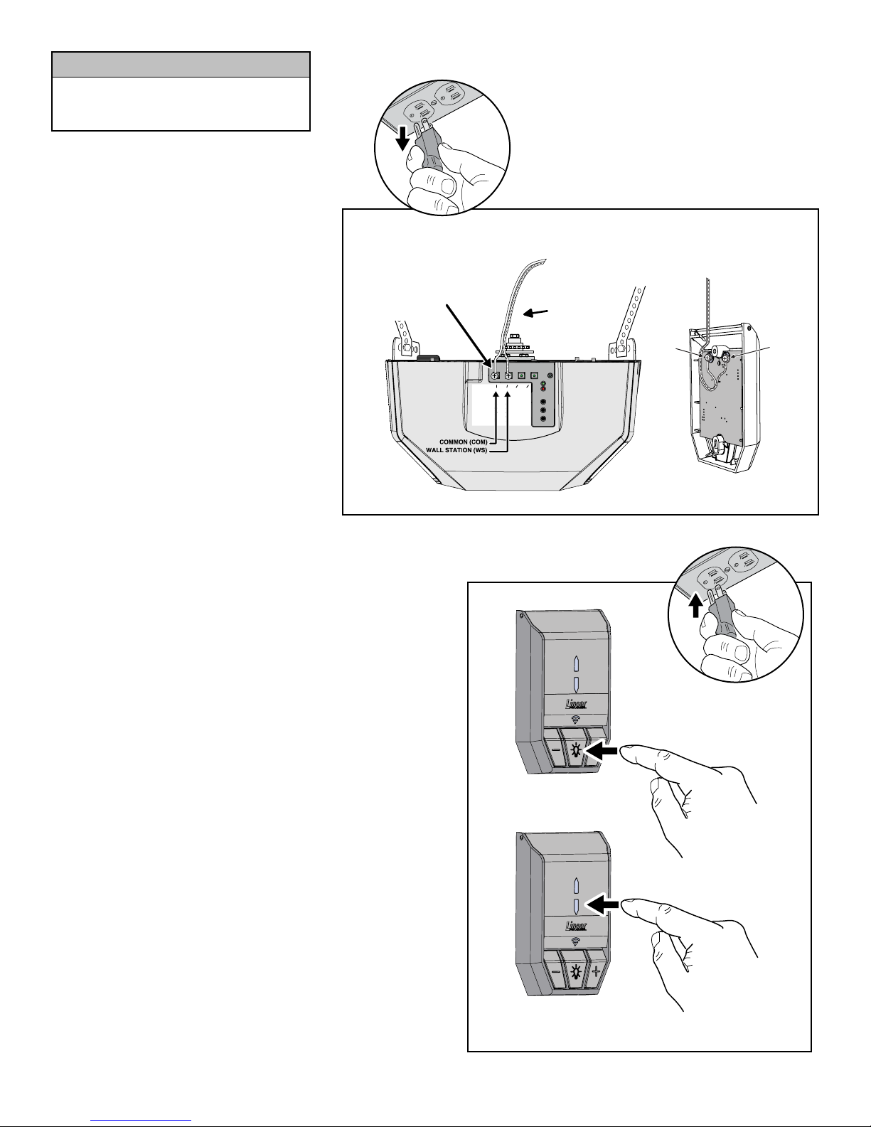
Wire the Wall Station
Always unplug the opener head unit’s
AC power cord before wiring or
repositioning the wall station!
CONNECTING WALL STATION TO OPERATOR
Connect the wall station to the garage
door opener head unit using either the
supplied or pre-existing wires.
CONNECT WALL STATION WIRES
TO WS AND COM TERMINALS
(POLARITY IS CRITICAL)
Use the wire that has a mark to connect
the COMMON (COM) terminals. Make
sure that you connect the COM terminal
on the wall station to the COM terminal
on the garage door opener head unit.
Next, connect the WALL STATION (WS)
terminal on the wall station to the WALL
STATION (WALL) terminal on the garage
door opener head unit.
Test the Wall Station
Once you have connected the wall station to the
garage door opener head unit, test if working properly
by using the wall station to operate the light and door
by taking the following steps.
COM WALL COM BEAM
CLASS 2 SUPPLY 28 VOLTS
! WARNING: Disconnect power before service. See
instruction manual for proper installation and service of battery.
SETTING THE LIMITS:
- Press and hold EITHER the UP or DOWN button to set LIMIT.
- Press and hold LEARN button.
- Release both buttons. When the light blinks and the alarm
beeps 2 times, the limit may be set.
- Press and hold the UP (or DOWN) button as needed to move
the door to the desired position.
- Press and release the LEARN button. The light blinks and
the alarm beeps 2 times to confirm setting.
Repeat the steps above to set the other limit.
P/N ????????
WIRES TO
WALL STATION
UP
DOWN
LEARN
COMMON
(COM)
WALL STATION
COM
WS
(WS)
• Plug the garage door opener head unit’s AC power
cord back into an outlet.
• Wait a few moments until the LED on the wall station
comes on.
• Press the light button to turn the light on and off.
• Press the cycle door button to operate the door.
If you are unable to operate the garage door using the
wall station’s buttons, please go to the Troubleshooting
Guide on page 6.
Turn light ON & OFF
OPEN & CLOSE door
3
LPWWS | Installation Instructions
Page 4
Using the Wall Station
Vacation Lock for Additional Security
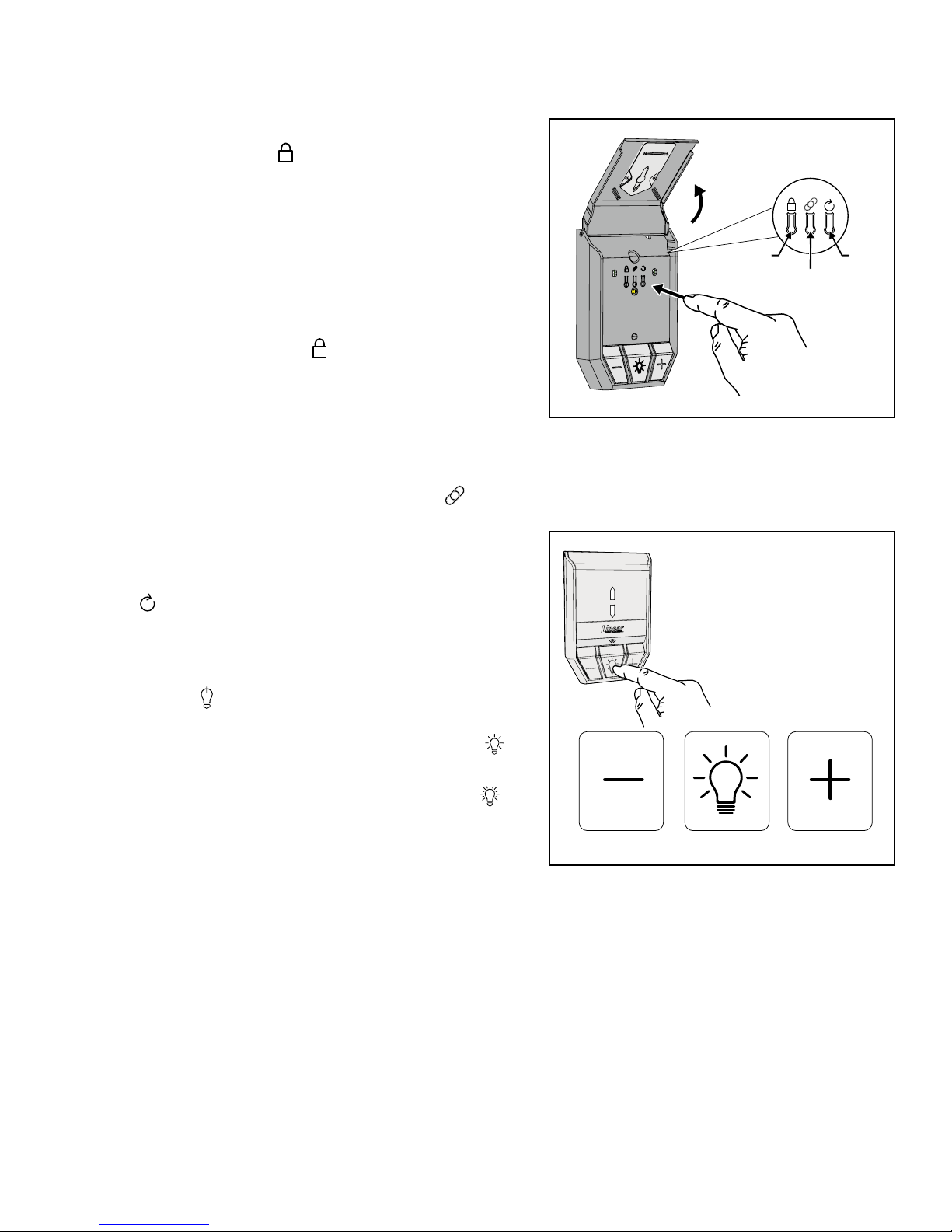
1 Open the wall station’s cover to access the Programming
Buttons. Press the LOCK ( ) button to prevent remote
controls from opening the door after the door is completely
closed. When the Vacation Lock is activated, the remote
controls can close the door, but not open it. The door can
still be opened or closed by using the wall station’s UP/
DOWN ARROW pushbutton.
NOTE: To signal that the vacation switch is locked, the
opener’s light will ash and the alarm will sound ve times if
a remote control is activated in an attempt to open the door.
2 Press the wall station’s LOCK ( ) button again to unlock
and return the operator to normal operation.
Wall Station Reset
If you change your home router or password you will need to
RESET your Wall Station.
1 To do a Wall Station RESET press the WiFi Link ( ) button
for 10 seconds, the RED LED blinks and then turns solid
RED. The Wall Station is now ready to re-link to a new or
updated home router.
2 To re-boot the Wall Station for software updates, press the
RESET ( ) button.
Controlling the Opener’s Light
FLIP THE LARGE COVER UP
TO ACCESS PROGRAMMING
BUTTONS.
LOCK
WiFi LINK
PRESS THE LIGHT BUTTON TO TURN
THE LIGHT ON OR OFF.
THE LIGHT WILL STAY ON UNTIL THE
LIGHT BUTTON IS PRESSED OR THE
OPENER IS CYCLED.
RESET
1 The opener’s light can be turned ON by pushing the wall
station’s on/off ( ) button. The light will stay on until the
button is pressed again or the opener is cycled.
2 To DECREASE the light brightness press the dimmer ( )
button.
3 To INCREASE the light brightness press the brighter ( )
button.
DIMMER ON/OFF BRIGHTER
LPWWS | Installation Instructions
4
Page 5
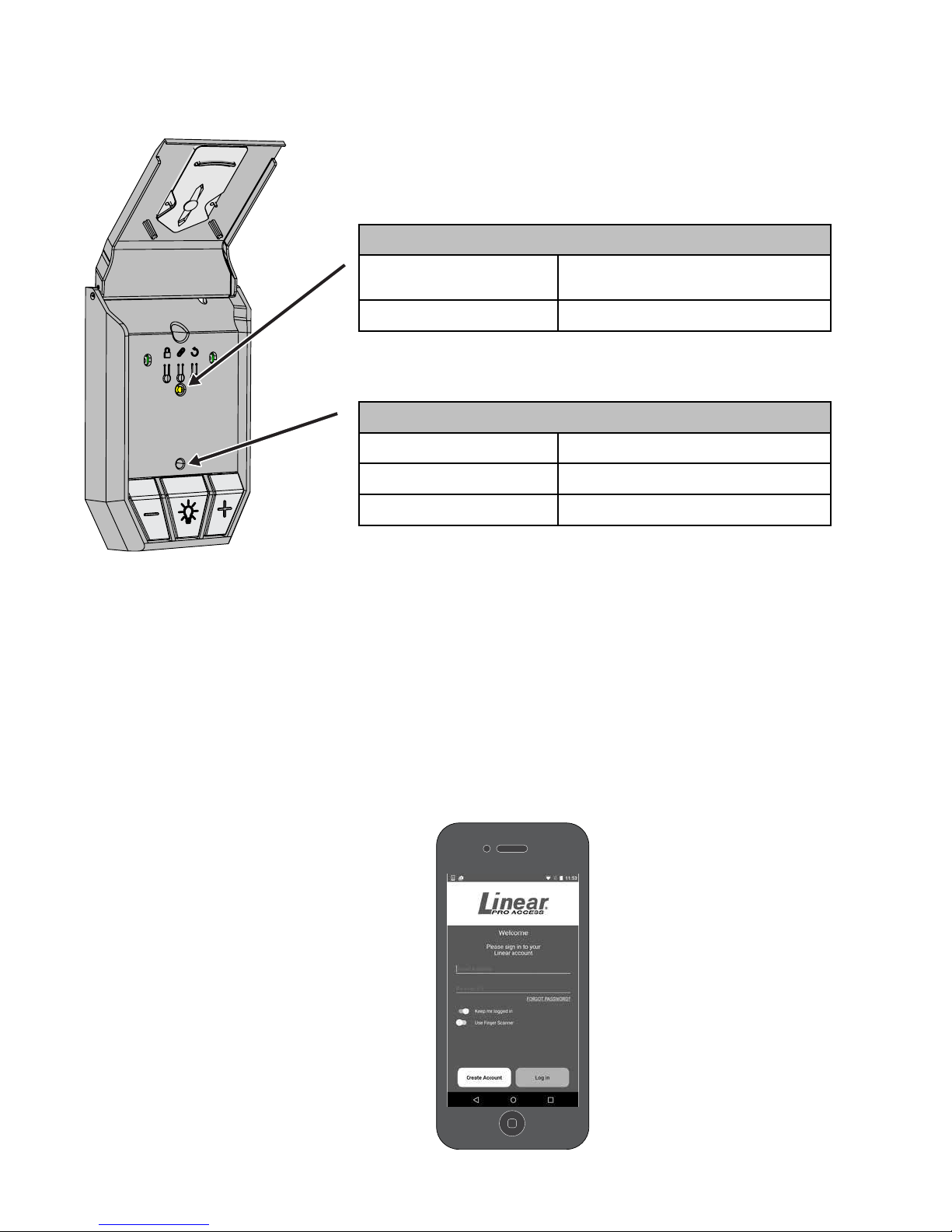
LED Lights on the Wall Station
The Wi-Fi wall station has two LED lights that convey information at a glance.
The top LED light provides information on the vacation mode.
Vacation Mode LED
ON Normal operation. Vacation mode
disabled.
FLASHING Vacation mode enabled.
The bottom LED light indicates the state of the Wi-Fi
connection and wall station.
Wi-Fi Connectivity LED
RED Not connected to Wi-Fi.
YELLOW Performing update
GREEN Connected to Wi-Fi.
LPA app Installation
Download, Register and Activate Application
Use your smart phone or tablet to visit your app store to download and install the LPA application. On
initial use you’ll be asked to register and create an account. Once complete, sign in with your new account
information.
Connect the Opener to app
Stand near Wi-Fi wall station. On your
mobile device, in the LPA app, tap the
plus sign at the bottom right of screen to
Connect Your Device. Follow directions in
app to Connect Your Device.
CARRIER
4:21 PM 22%
New Account
Create a Mighty Mule Account
First Name
Email Address
Password
Conrm Password
Password must be 6 or more characters, include at least one
Last Name
upper and lower case character and a number.
Back Create Account
5
LPWWS | Installation Instructions
Page 6
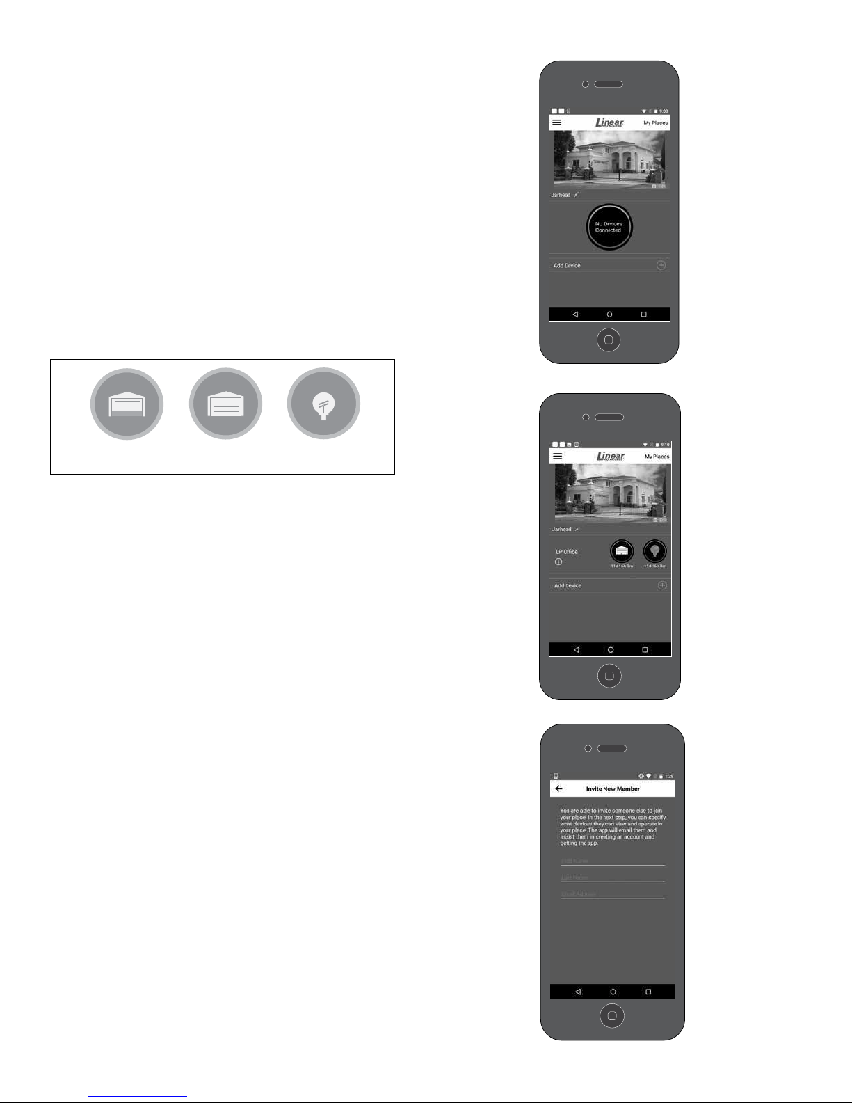
Use the LPA app
DOOR FULLY
CLOSED
LIGHT ON / OFFDOOR PARTIALY
OR FULLY OPEN
The app’s main screen indicates the current state of
the garage door and allows operation. If your garage
door is fully closed, the app will show the door fully
closed. If the garage door is partially or fully open,
the app will show the door open.
To close or open the garage door, tap the garage
door icon. Likewise, tap the light icon to turn the
garage door light on or off.
For a detailed view of the device, tap a device icon.
From here you can adjust the brightness of the light,
and you can view a history of who operated the
device.
CARRIER
4:21 PM 22%
App
Select this icon to see site menu
Skip Intro
CARRIER
4:21 PM 22%
App
Site One
Group Name
Manage Your Devices and Members
Tap the Site Menu icon (three circles stacked on
top of each other) located in the top left of the
screen. From here you can remove devices from
your site, invite new members to join your site
and remove existing members from your site.
Invite Others
To invite a new member, select the Invite New
Member button at the bottom of the Site Menu.
You will be asked to set their permission level.
There are three classes of members in this
application:
• You, the Entrematic app administrator, who
created the site and added devices.
• Administrators, who can invite others, set/
change permissions, and operate and view all
devices.
• Regular members, who can operate and view
only specied devices.
Garage
Light
All Garages
OPEN CLOSE
CARRIER
All Lights
ON OFF
4:21 PM 22%
Device Name
OPEN – 50%
Garage
Show garage door on My Home Site
CONNECTED DEVICES
ON – 50%
Light
LPWWS | Installation Instructions
Show garage light on My Home Site
6
Page 7
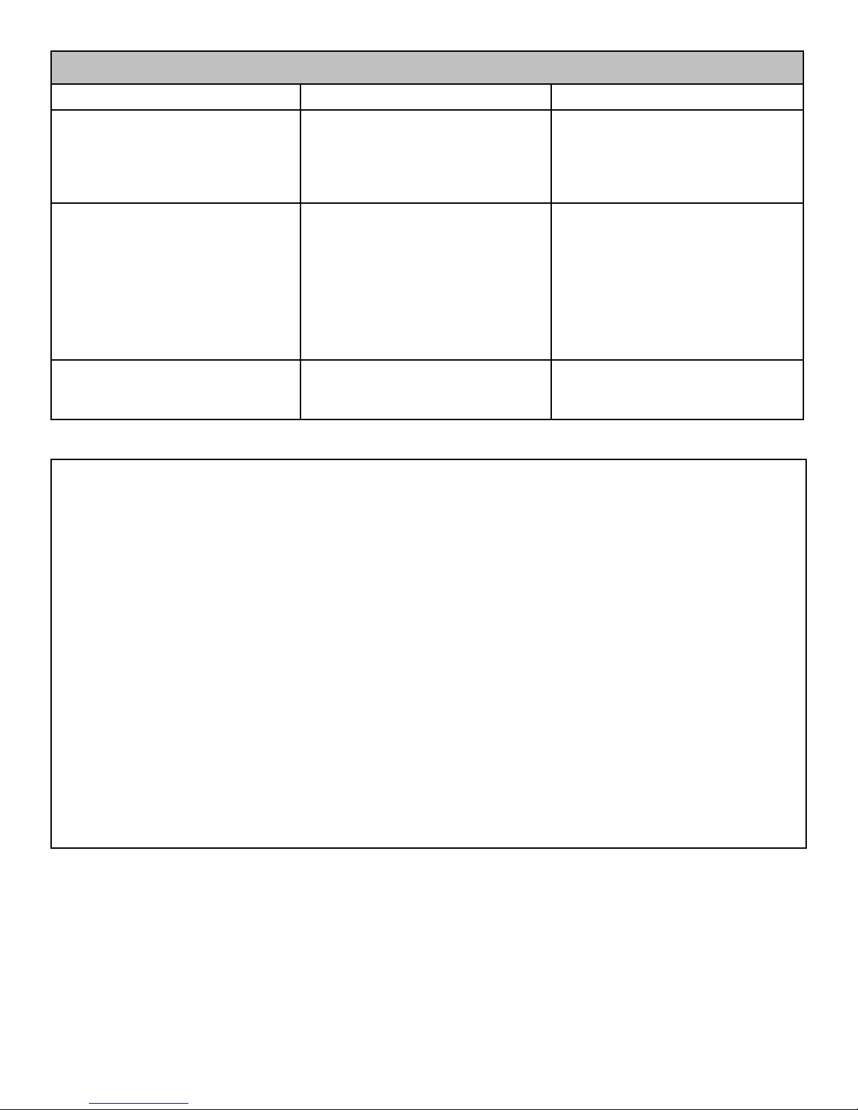
TROUBLESHOOTING GUIDE
Condition/LED Color Possible Cause Possible Solution
Wall station does not power on. 1. Incorrect wiring 1. Check wall station wiring for
correct polarity.
2. Conrm head unit is plugged in
and has power.
3. Call tech support.
RED 1. Wall station has not been as-
signed to an access point.
2. Wall station is not within range
of its assigned access point.
3. Antenna interference.
1. Use the mobile app to congure
the wall station’s access point.
2. Relocate the wall station or relocate the homes access point.
3. Ensure area around the wall station is free from metal objects
and electrical wires. Reference page 2 of this manual for
checking Wi-Fi signal.
YELLOW 1. Checking for updates 1. No action required from user;
this behavior is normal and
temporary.
WARNING: Changes, modications or adjustments not expressly approved by GTO Access Systems, LLC could void the user’s
authority to operate this equipment. There Are No User Serviceable Parts.
NOTICE: This equipment has been tested and found to comply with the limits for a Class B digital device, pursuant to part 15
the FCC. These limits are designed to provide reasonable protection against harmful interference in a residential installation.
This equipment generates, uses and can radiate radio frequency energy and, if not installed and used in accordance with the
instructions, may cause harmful interference to radio communications. However, there is no guarantee that interference will not
occur in a particular installation. If this equipment does cause harmful interference to radio or television reception, which can be
determined by turning the equipment off and on, the user is encouraged to try to correct the interference by one or more of the
following measures:
—Reorient or relocate the receiving antenna.
—Increase the separation between the equipment and receiver.
—Connect the equipment into an outlet on a circuit different from that to which the receiver is connected.
—Consult the dealer or an experienced radio/TV technician for help.
NOTICE: This device complies with part 15 of the FCC. Operation is subject to the following two conditions: (1) this device may
not cause interference, and (2) this device must accept any interference, including interference that may cause undesired operation of the device.
This device complies with Industry Canada license-exempt RSS standard(s). Operation is subject to the following two conditions:
(1) this device may not cause interference, and (2) this device must accept any interference, including interference that may cause
undesired operation of the device.
7
LPWWS | Installation Instructions
Page 8

 Loading...