

Page 1

F O R T H E L O V E O F M U S I C
™
MODEL 401©
(1981-MSRP $159.00)
OWNER'S MANUAL AND
INSTALLATION GUIDE
INTRODUCTION
Your new Linear Power™ 401© amplifier employs a sophisticated design
combining reliability, high power, low distortion, and freedom from external noise.
When properly installed, it will give long and faithful service. When combined with
other high quality components, it will be the heart of a superb system. Thank you
for purchasing a Linear Power™ Product.
INSTRUCTIONS
Read the following instructions completely through. If they appear too
complicated, we recommend that you have an authorized LINEAR POWER™
Dealer do the work.
MOUNTING
1. Amplifier Cooling: The amplifier will operate best if it is kept as cool as
possible. Mount in a position that allows air to flow freely through the fins. Be
sure there is ample space above the amplifier to avoid trapping heated air rising
from the amplifier. The amplifier should not be mounted upside down.
2. Accessibility: Mount your amplifier in a position that allows ample room for
installation, removal and attachment of leads, and gain adjustments.
3. Insulation: Be sure that the metal case of the amp does not touch the metal of
the car. Do not remove or damage the rubber grommets that provide electrical
insulation and vibration isolation.
© 2008 Linear Power, Inc. - ALL RIGHTS RESERVED
LINEAR POWER™ is a trademark of Linear Power, Inc.
1
Page 2

WIRING
1.FUSE: A fuse of the proper size must be installed in line with the main power in
order to prevent damage to your wiring. It should be connected to the battery
positive terminal or as close to the battery as possible. Use the fuse holder and
fuse provided and replace only with the same size fuse. The LINEAR POWER™
401© uses a 5 amp AGC fuse.
WARNING: OVERFUSING WILL DAMAGE THE AMPLIFIER
2.MAIN POWER
The free end of the fuse holder wire should be connected to the large red wire
from the amplifier. IMPORTANT: Solder or crimp all connections. Connect the
other end of the fuse holder to the + terminal on the battery.
3.MAIN GROUND
Connect the large black wire to a solid frame member via a bolt or self-tapping
screw. If in doubt about the adequacy of the ground, extend the ground wire to
the negative battery terminal.
4.+12V FOR TURN-ON
The red and white wire is not a main power source for the amplifier, but acts as
an electrical switch to turn the amplifier on and off. It should be connected to the
power antenna lead from the radio. Where no power antenna lead exists, a
source of 12 volts connected through a toggle switch will do. DO NOT
CONNECT DIRECTLY TO A SOURCE THAT WILL LEAVE THE AMPLIFIER
PERMANENTLY ON, AS THIS WILL DRAIN THE BATTERY.
5.SIGNAL INPUT
The RCA (Phono) Jack inputs will accommodate either high or low level signals,
ranging from 200mv to 5 volts. For use with a high level source that is intended to
drive speakers directly, attach speaker leads to male RCA Plugs and insert into
the inputs. Make sure that the positive speaker leads are attached to the
striped wire of the high level adaptor.
6.SPEAKER OUTPUT
Connect the gray wire to the right speaker's (+) terminal. Connect the green wire
to the left speaker's (+) terminal. Connect one of the black wires to the right
speaker's (-) terminal. Connect the other black wire to the left speaker's (-)
terminal. (See wiring diagram next page)
© 2008 Linear Power, Inc. - ALL RIGHTS RESERVED
LINEAR POWER™ is a trademark of Linear Power, Inc.
2
Page 3
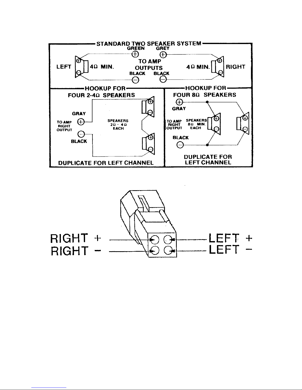
401 Speaker Connector
OPERATION IN BRIDGE MODE
The Model 401© amplifier must use an external pre-amp or crossover to be used
as a bridgeable amplifier. They must be bridged using a Linear Power™
crossover such as the Linear Power™ XO-1
©, XO-2©, or similar brand
crossover or pre-amp with inverting capabilities. One channel of the inputs of
these amplifiers must receive an inverted signal in order to have the needed
inverted signal on one channel at the output. Speaker connection can then be
made from LEFT (+) and RIGHT (+). This amplifier is a minimum of 8-ohm
bridgeable, for utmost reliability and sound quality. This amp is not recommended
for 4–ohm bridged loads.
© 2008 Linear Power, Inc. - ALL RIGHTS RESERVED
LINEAR POWER™ is a trademark of Linear Power, Inc.
3
Page 4

OPERATION/ADJUSTMENT
Apply power to the system. Amp will come on after a slight delay. Turn volume
control up on tape deck or radio. If power output is adequate, leave gain control
where it is. If volume is low slowly increase gain on the amplifier by turning the
gain clockwise with a screwdriver. On some radios, which have very low-level
outputs, a Preamp or Line Amp may be necessary.
NOTE: IT IS VERY IMPORTANT THAT THE GAIN CONTROL BE TURNED
DOWN AS FAR AS POSSIBLE. IN ORDER THAT UNWANTED ENGINE NOISE
BE KEPT TO A MINIMUM.
GENERAL TROUBLESHOOTING
NO SOUND: Check all connections. Check main power fuse. Check accessory
fuse. With a trouble light or meter be sure +12V is present at the amplifier on (1)
The large Red Wire (2) The (Red/White) wire but not at the large Black. Check by
substitution or other method for proper operation of music source.
BLOWS FUSE: Check all connections to be sure all power wires and speaker
wires do not touch ground or each other. Re-check polarity of main power wires.
SHUTS OFF: As this amplifier is equipped with a thermal and a short circuit
shutdown system in the unlikely event of excessive temperatures due to high
ambient temperature, improper speaker impedance, etc. The amp will turn itself
off. If this happens, the amp will turn itself back on when cool enough. To avoid
damage to the speakers, turn the volume to a minimum while waiting for the amp
to turn itself back on.
NOISE NOTES
Unwanted noise is the worst single problem encountered in automotive amplifier
installations. Most noise problems start at the music source. Your LINEAR
POWER amplifier will accurately reproduce any sound present in the signal path.
NO amplifier can discriminate between music and engine noise. Several basics
must be kept in mind when preventing noise problems.
1.The hookup method with the least noise in one vehicle may be the noisiest in
another.
2.Most noise problems start at the music source. Your LINEAR POWER™
amplifier will accurately reproduce any sound present in the signal path. NO
amplifier can discriminate between music and engine noise.
© 2008 Linear Power, Inc. - ALL RIGHTS RESERVED
LINEAR POWER™ is a trademark of Linear Power, Inc.
4
Page 5

3.Many noise problems exist due to a lack of car maintenance. A general tune-up
and periodic check of the vehicle's charging system should be made.
4.In some situations the complete elimination of engine noise may not be
possible. In those cases, one can only hope for an acceptable degree of
reduction. Consult your professional auto sound dealer to aid you in those
"tough" cases.
INSTALLATION RULES
1. Use shielded cables whenever a preamp level music source is used.
2. All connections must be tight, free from corrosion and paint, etc. and insulated.
3. Route all signal cables away from existing wiring in the vehicle.
4. If possible, avoid mounting the amplifier in the dash or on the firewall, as noise
may be induced due to the proximity of noisy wiring and switches.
NOISE TROUBLESHOOTING PROCEDURES
1. Start engine and let idle.
2. Turn system on. ADJUST INPUT GAIN ON AMP SO THAT IT IS TURNED
DOWN AS FAR AS POSSIBLE TO STILL PRODUCE ADEQUATE LISTENING
LEVELS.
3. Slowly increase and decrease engine speed.
4. Take note as to the type and amount of noise while slowly varying the volume
control on the music source from minimum to average levels.
5. If noise is a popping or ticking sound, increasing in speed with engine speed,
the source is probably the ignition system. If the noise is a "whistle," the source is
the alternator. If the noise is present only when the volume is turned up, both
types of noise require similar treatments.
6. Unplug the inputs to the amplifier at the amp. Again, listen to the amount of
noise. If the noise disappears, install a noise kit (which can be purchased at any
Radio Shack or other electronic outlet.) (See note A)
7. If the noise remains when the inputs are removed, re-route the power
connections and check for the proper ground connections (see note B).
© 2008 Linear Power, Inc. - ALL RIGHTS RESERVED
LINEAR POWER™ is a trademark of Linear Power, Inc.
5
Page 6

NOTES
A. Install a noise kit in the main power to the music source. If the music source
has a dimmer lead, install a noise kit there also. Check all grounding points for
corrosion, paint, ECT. Scrape clean, and retighten if necessary. If noise
continues to persist, refer to note C.
B. Re-route the main power ground to a different location in the vehicle. Listen
carefully to the amount of engine noise through the system each time the ground
is changed. If relocation of the power ground has little or no effect, obtain a high
current choke (coil) with a current rating of at least one and one half times the
maximum current rating of the amplifier and splice inline with amp main power
wire. IMPORTANT: SOLDER AND INSULATE ALL CONNECTIONS. If the
noise still persists mount the amp in a different location farther away from the
engine compartment. Be sure all main power wires to the amp are routed away
from existing wiring in the vehicle.
C. Touch the center pin of the music source male plug to the center hole of the
amplifier female jack so that the music is heard. Prevent the outer ground contact
from touching the female jack on amp. If this procedure causes noise to
disappear modify the input cables by carefully removing 1-2 of the outer
insulation exposing the ground braid. Cut the braid and fold back Strip 2-3 of
insulation off a scrap piece of wire and wrap around the ground braid next to the
plug closest to the amp and wrap the entire connection with electrical tape. Try
grounding this signal ground at several different locations in the vehicle while
carefully listening to the amount of engine noise at each location. Attach this
signal ground wire to the location, which causes the least amount of engine
noise. Only one input plug needs the signal ground wire attached, the other input
need only have its ground braid broken.
To obtain modification, service or repair, please contact our ONLY Authorized
LINEAR POWER™ Product Service Center:
3 4 5 5 L A N EL L L A N E, P E A R L, M S 3 9 2 0 8 (6 0 1) 9 3 2 – 8 4 7 7
SERVICE OR REPAIR
T.I.P.S. INC.
3455 Lanell lane, Pearl, MS 39208
(601) 932-8477
E-mail: [email protected]
© 2008 Linear Power, Inc. - ALL RIGHTS RESERVED
LINEAR POWER™ is a trademark of Linear Power, Inc.
™
6
Page 7

Specifications
401©
Power output @ 4 ohms RMS @ 12.5 volts
THD @ full output 20-20KHz +/- 1dB
20X2
<.15%
Signal to Noise ratio >95 dB
Intermodulation Distortion .3%
Damping factor @ 4 ohms >200
Frequency Response +/- 1 dB 12Hz to 150KHz
Slew Rate in volts per microsecond 6 V/uS
Dynamic headroom 1 dB
Current Draw @ Idle/Max .75A/7.5A
Fuse rating (12 Volt Power Feed) 5A
3 4 5 5 L A N E L L L A N E, P E A R L , M S 3 9 2 0 8 (6 0 1) 9 3 2 - 8 4 7 7
© 2008 Linear Power, Inc. - ALL RIGHTS RESERVED
LINEAR POWER™ is a trademark of Linear Power, Inc.
™
7
 Loading...