

Page 1
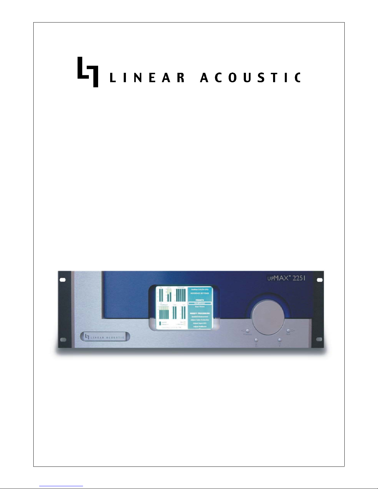
UPMAX 2251
5.1-Channel Surround-Field Synthesizer
User Guide
Page 2

Page 3
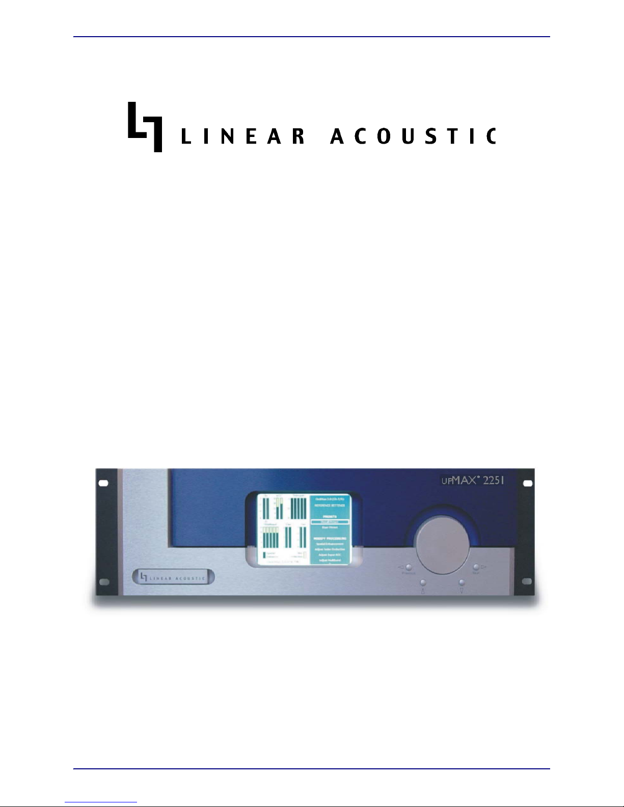
UPMAX 2251
5.1-Channel Surround-Field Synthesizer
User Guide
Release Date: January, 2004
Software Version: 0.805 and Later
Linear Acoustic Inc.
Phone: 888-292-3117
FAX: 973-267-4525
email: www.LinearAcoustic.com
Page 4

Warranty Information
DISCLAIMER OF WARRANTIES: Products manufactured by Linear Acoustic Inc. are warranted
against defects in material and workmanship for a period of two (2) years from the date of purchase.
THERE ARE NO OTHER IMPLIED OR EXPRESS WARRANTIES AND NO WARRANTY FOR MERCHANTABILITY OR FITNESS FOR A PARTICULAR PURPOSE.
During the warranty period Linear Acoustic Inc. will repair, or at our discretion replace, components
which prove to be defective, provided the unit is returned, shipped pre-paid to us directly with a return
authorization (RA) number clearly marked on the packaging. Please note, this RA number must be
present or package will be refused and returned to sender.
All requests for repairs MUST include the unit serial number to ensure quick and accurate service.
DEFECTS CAUSED BY UNAUTHORIZED MODIFICATIONS, MISUSE OR ACCIDENTS, UNAUTHORIZED CUSTOMER REPAIRS, OR ANY FURTHER DAMAGE
CAUSED BY INADEQUATE PACKAGING FOR SERVICE RETURN ARE NOT COVERED BY THIS WARRANTY.
PLEASE SAVE THE SHIPPING CARTON AND ALL PACKING MATERIALS. FAILURE
TO RETURN UNIT IN ORIGINAL SHIPPING CARTON AND PACKING MATERIALS
WILL RESULT IN A CHARGE FOR NEW SHIPPING MATERIALS.
LIMITATION OF PERIOD OF ACTION ON CONTRACT: No action, regardless of form,
arising out of the transactions under this agreement may be brought by buyer, its successors, agents
and/or assigns, more than three years from date of purchase.
LIMITATION OF LIABILITY: It is understood and agreed that Linear Acoustic’s liability whether
in contract, in tort, under any warranty, in negligence or otherwise shall not exceed the cost of repair
or replacement of the defective components and under no circumstances shall Linear Acoustic be liable
for incidental, special, direct, indirect or consequential damages, or loss of use, revenue or profit even
if Linear Acoustic or its agents have been advised, orally or in writing, of the possibility of such damages.
Page 5

Linear Acoustic upMAX 2251 User Guide
Table of Contents
List of Figures...........................................................................................................................................vi
Chapter 1: Introduction...................................................................................................................5
1.1 Principles of Operation..........................................................................................5
1.2 Signals and Levels ...................................................................................................7
1.3 Downmix Compatibility ........................................................................................8
Chapter 2: Connections and Setup.......................................................................................9
2.1 Unpacking and Inspection ....................................................................................9
2.2 Installation ...............................................................................................................9
2.3 Rear Panel ..............................................................................................................10
2.3.1 Connection Ports .................................................................................10
Chapter 3: Applications................................................................................................................13
3.1 Typical Scenarios ..................................................................................................13
3.1.1 Two-Channel Commercials ................................................................14
3.1.2 Sporting Events ....................................................................................15
3.1.3 Music Awards-Type Events................................................................16
3.2 Factory Presets ......................................................................................................17
Chapter 4: Menus..............................................................................................................................19
4.1 Main Menu.............................................................................................................19
4.1.1 Modify Processing Menu ....................................................................19
4.1.2 Setup Menu ...........................................................................................21
4.1.3 System Info ...........................................................................................23
4.1.4 System Options.....................................................................................23
4.1.5 Lock Front Panel..................................................................................24
Chapter 5: Specifications............................................................................................................25
v
Page 6

Linear Acoustic upMAX 2251 User Guide
List of Figures
1-1 Audio Block Diagram .........................................................................................................................6
2-1 Rear Panel ...........................................................................................................................................10
3-1 UPMAX 2251 in a commercial upmixing application .................................................................14
3-2 UPMAX 2251 with Dolby DP572 Dolby E Decoder .................................................................15
3-3 UPMAX 2251 in a live sports application .....................................................................................16
3-4 UPMAX 2251 in a music awards-type program ...........................................................................17
4-1 Main Screen showing level meters to the left and menus to the right. .....................................19
4-2 Modify Processing menu; scroll down to access Ext L/R Mix (as shown on right menu) ...20
4-3 Setup menu .........................................................................................................................................21
4-4 Save Preset menu before (left) and after (right) saving ................................................................23
vi
Page 7

Linear Acoustic upMAX 2251 User Guide
Chapter 1: Introduction
The Linear Acoustic UPMAX 2251 produces a 5.1 channel audio signal that is perfect for
eventual transmission via Dolby Digital (also known as AC-3) to all consumers. The unit
accepts a 2-channel input and “upmixes” it to fill as many of the 5.1 output channels as the
user selects. Any input signal from mono to LtRt (Left Total/Right Total) surround encoded audio can be applied to the Main Input and an output will be produced that maintains consistency with other 5.1 channel programming.
Further, external discrete sources of audio such as announcer or stereo crowd can be applied to the unit via its Mix Inputs and can be selectively mixed with the audio produced
by the upmixing process. A subwoofer, or LFE channel can also be selectively created
from the Main Input audio or via the discrete LFE Mix Input.
The UPMAX 2251 provides the following features:
• Advanced upmixing algorithm for stable, convincing surround experience.
• Fully compatible with all surround formats including Dolby Digital
• Upmixed surround field is infinitely adjustable in width and depth.
• External inputs allow mixing of discrete and upmixed audio signals.
• Relay bypassed digital inputs for “mission critical” broadcast applications.
• Simple front panel user interface and display.
• Optional HDSDI (SMPTE 292M) input module (available Q1, 2004)
1.1 Principles of Operation
The UPMAX 2251contains two paths for audio signals. The first path contains an upmixer,
a bass extension filter to create the LFE (Low Frequency Effects) or subwoofer channel,
and a simple but powerful set of mix controls to vary each element of the surroundfield.
The second path provides discrete inputs for the Center, LFE, Ls (Left Surround), Rs
(Right Surround), Lf (Left Front) and Rf (Right Front) channels. The upmixed and discrete
outputs are selectively combined to allow for the addition of specific audio elements to the
upmix-derived elements.
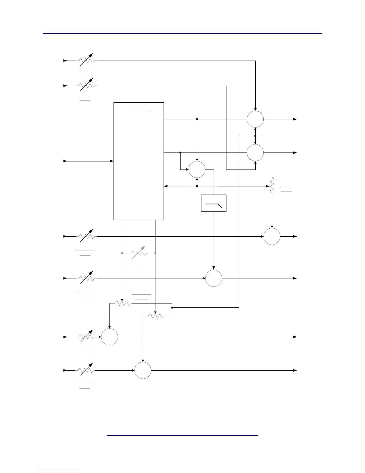
Please refer to Figure 1-1. It should be noted that this diagram is a general representation
of signal flow. Please consult the appropriate section of this manual for an accurate description of actual functionality.
5
Page 8
Linear Acoustic upMAX 2251 User Guide Introduction
Mix In
Lf
Mix In
Rf
Ext Lf
Level
Ext Rf
Level
UPMIXER
Left
+
Main
Out Lf
Main In
Lt/Rt
Mix In
Center
Mix In
LFE
Ext Center
Level
Ext LFE
Level
Surround
Surround
Width
Surround
Depth
Right
Center
+
80 Hz
+
+
+
Main
Out Rf
Center
Width
Main
Out C
Main
Out LFE
Mix In
Ls
Ext Ls
Level
Mix In
Rs
Ext Rs
Level
+
+
Figure 1-1 Audio Block Diagram
6
Main
Out Ls
Main
Out Rs
Page 9

Linear Acoustic upMAX 2251 User Guide Introduction
Two-channel audio is applied via the Lt/Rt Main Input. The audio is upmixed to produce
Left, Right, Center, and Surround signals. The Left and Right outputs of the upmixer are
passed unmodified to the Left and Right Main Output.
The Center channel output of the upmixer is passed through the Center Width control
which varies the amount of center channel audio present at the Center Main Output versus
how much is summed back into the Left and Right Main Output. A setting of 100% indicates that all of the upmixed Center audio is being fed to the Center Main Output, while
0% indicates that all of the upmixed Center audio is being fed back into the Left and Right
Main Output. The 0% setting is the same as “Phantom Center” mode common on some
decoders.
The Left, Right, and Center outputs of the upmixer are combined then 80Hz low pass filtered and when selected via the LCR Sum To LFE switch are passed via the LCR Sum
Level control to the LFE Main Output.
The Surround output of the upmixer is passed through the Surround Depth control
which varies the amount of surround information present at the Ls/Rs Main Output versus how much is summed back into the Left and Right Main Output. A setting of 100%
indicates that all of the upmixed Surround audio is being fed to the Ls/Rs Main Output,
while 0% indicates that all of the upmixed Surround audio is being mixed back into the
Left and Right Main Output.
All outputs of the upmixer can also be selectively combined with signals applies to the Mix
Inputs. The Mix Inputs are available for all channels and have Mix Level controls that vary
from off to +6dB. Note that the +6dB range is provided for convenience, but a full-scale
signal applied to these inputs can be increased to clipping, so settings above 0dB should
be used carefully and sparingly.
1.2 Signals and Levels
The Linear Acoustic UPMAX 2251 is calibrated for -20dBFS environments, but will work
fine with other reference levels with the minor caveat that the analog LtRt utility output
(on the LtRt/Aux DB-25 connector) is fixed at -20dBFS=+4dBu.
The sample rate of the UPMAX 2251 is nominally 48kHz, but the unit will run at other sam-
ple rates as determined by the signal applied to the AES REF input. Please note that currently this causes the test tones to change slightly in frequency, but has no effect on the
program audio.
Below is a list of the inputs and outputs of the UPMAX 2251:
• Lt/Rt Main Input - Main input to upmixer
• Mix Inputs (C/LFE, Ls/Rs, Lf/Rf) - Direct mix inputs to the main output channels
7
Page 10

Linear Acoustic upMAX 2251 User Guide Introduction
• Main Outputs (Lf/Rf, C/LFE, Ls/Rs) - Main audio outputs in SMPTE 320M format
• LtRt Main Output - A utility two-channel downmix of the 5.1 channel program (this
output is also available as an analog signal on the LtRt/Aux connector)
1.3 Downmix Compatibility
Downmixing is the process where the individual channels of a Dolby Digital signal are
combined in order to be reproduced from a given number of channels. For example, a 5.1
channel program must be downmixed to be reproduced from a stereo speaker system and
so the left and right channels are combined with the left and right surround signals and an
attenuated version of the center channel before being output as a stereo signal. This type
of signal is called LoRo (for Left only/Right only).
Downmixing may also produce an LtRt compatible signal by performing a pseudo-surround encode. A 90-degree phase shift is applied to the surround signals in the Dolby Digital encoder prior to the actual encoding stage so that after downmixing from 5.1 to 2channels in the consumer decoder the signal can be heard in surround by the many consumers that only have a matrix surround decoder.
An extremely important design goal of the Linear Acoustic UPMAX 2251 was that the out-
put be downmix compatible. Not only stereo and surround, but also mono- and it had to
sound good in 5.1! A tall order that has been satisfied.
One important thing to remember is that to ensure widest compatibility, the Dolby Digital
encoder must be set to apply a 90-degree phase shift. Luckily, this is the default position
for most of the presets, however please consult the encoders user manual to find the menu
location where this setting can be checked.
8
Page 11

Linear Acoustic upMAX 2251 User Guide
Chapter 2: Connections and Setup
This chapter covers all required connections for the Linear Acoustic UPMAX 2251.
2.1 Unpacking and Inspection
Before unpacking the unit, inspect the outer carton for shipping damage. If the carton
shows damage, inspect the unit in those areas. Please save the carefully designed shipping
carton and packing materials. In the unlikely event that the unit needs to be returned to the
factory, alternate cartons or packing materials may not be adequate and can cause damage
not covered by warranty.
The following essential items are provided with the unit:
• Warranty information: Fill out and return the postage-paid warranty card (please) to
Linear Acoustic to ensure your software and documentation are kept up to date.
• One power cord (US style).
• Bag containing rack-mount screws and washers, a male DB-25 connector and shell for
either the GPI/O or LtRt/Aux Outputs, and this manual.
2.2 Installation
UPMAX 225 installation requires:
• three standard rack space units with ADEQUATE VENTILATION;
• standard 75 BNC cables for digital signal connections;
To connect to digital equipment with 110 XLR connectors, use impedance-matching transformers (available from Canare, Neutrik and other manufacturers).
• an AES reference supplied to the AES REF input PRIOR to powering the unit on.
• a suitable monitoring system.
We recommend a multichannel listening environment with at least six speakers to
properly monitor a 5.1-channel program. An inexpensive system (less than $400) available from Klipsch easily satisfies this requirement.
9
Page 12
Linear Acoustic upMAX 2251 User Guide Connections and Setup
2.3 Rear Panel
The rear panel of the UPMAX 2251 contains its electrical I/O.
WARNING: Before applying power, check the Voltage Selector switch.
2.3.1 Connection Ports
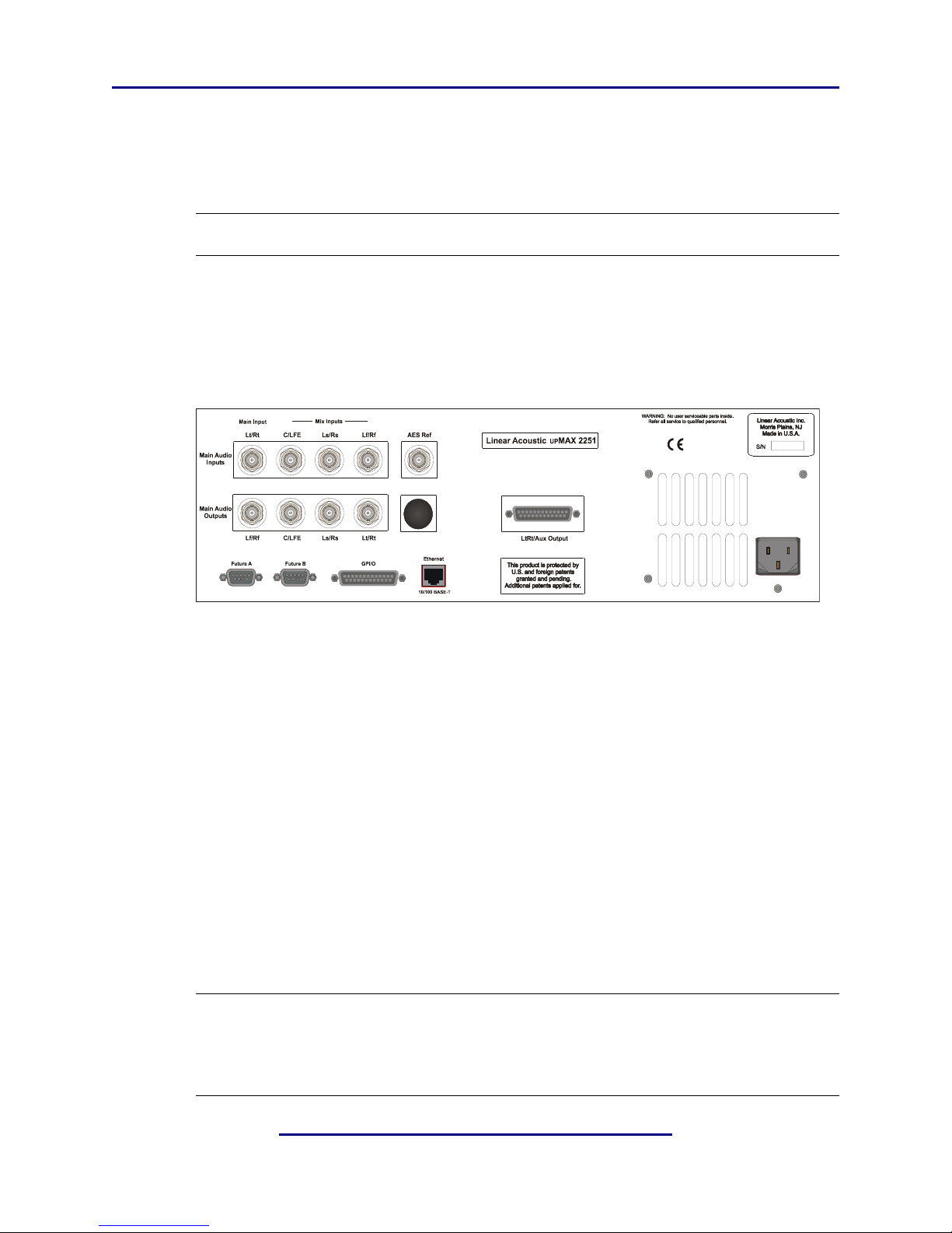
All of the UPMAX 2251’s connections are on the rear panel and are described in detail below. See Chapter 5: Specifications for specific pinouts.
Figure 2-1 Rear Panel
• Main Audio Input: Connect the PCM signal which will be upmixed to create a 5.1
channel signals to this input.
• Mix Inputs: PCM signals connected to these inputs can be selectively mixed with the
output of the upmixing algorithm. These are useful for adding announcer via the C
(center) input, or stereo “natural,” “crowd,” or “ambience” audio via the Ls/Rs (Left
surround/Right surround) inputs. Lf/Rf (Left front/Right front) inputs are useful for
placing audio in the left and right main outputs with no additional processing.
• Main Audio Outputs: Main processed digital audio outputs with the SMPTE 320M
standard channel configuration: Left/Right, Center/LFE, Left Surround/Right
Surround. An Lt/Rt compatible downmix of the 5.1 channel output is always available
on the Lt/Rt output connector and is useful for monitoring or feeding systems such
as NTSC which support only two audio channels.
NOTE: The main audio inputs are hard-bypassed to the Main Audio Outputs during
boot and bypass (power off) conditions to support mission-critical applications. Under these circumstances, each input connector bypasses to the
output connector directly below it passively maintaining audio continuity.
10
Page 13

Linear Acoustic upMAX 2251 User Guide Connections and Setup
• AES REF: Connect an AES plant reference signal to this connector (not a video or word
clock reference). The signal may be an AES Black or AES signal containing audio.
NOTE: A valid AES signal is required on the AES REF connector for the system to
operate (not video or word clock).
• Lt/Rt/Aux Output: This is a combination balanced analog and AES compatible digital output of the LtRt version of the main program audio.
• GPI/O: Connect to the GPI/O outputs of your automation system or routing or master control switcher to control special processor functions and recall presets. Note that
GPI A and B require a held contact closure to ground for the duration of the function.
However, GPI 1-6 require only a momentary contact closure to ground; if held, other
numerical GPIs cannot be selected.
• ETHERNET: Automatically senses 10 or 100BASE-T Ethernet connectivity. The
UPMAX 2251 will appear on the network as: upMAX followed by the units serial num-
ber (i.e. upMAX-04301). The units workgroup is defaulted to WORKGROUP with no
password. This connection is primarily used to support a software remote control running on a standard PC clone via a standard network connection.
• Metadata In: Connect to the Professional Audio Metadata output of a VANC de-embedder or Dolby E decoder to input external metadata (not currently supported, awaiting approval from Dolby Laboratories).
• Metadata Out: Connect to the metadata input of a Dolby E or Dolby Digital encoder
(not currently supported, awaiting approval from Dolby Laboratories).
11
Page 14

Linear Acoustic upMAX 2251 User Guide Connections and Setup
12
Page 15

Linear Acoustic upMAX 2251 User Guide
Chapter 3: Applications
The UPMAX 2251 is intended to be used either in the production or distribution stages of
5.1 channel programming, and also selectively in transmission environments. Cable and
satellite facilities may find it useful as the distribution and transmission sections are usually
very close together. For terrestrial emission (transmission) applications such as at DTV stations, the Linear Acoustic OCTiMAX 5.1 may be a more appropriate choice as it contains
requisite dynamic range processing and additional useful features such as voice-over.
The Linear Acoustic UPMAX 2251 is
nel mix (if one is available), rather it is a useful tool to create one!.
That being said, the UPMAX 2251 is an excellent tool useful in either creating a 5.1 channel
version of a program when few or no other elements exist, and also for creating a solid
foundation for a true discrete multichannel mix.
This chapter discusses several applications of the UPMAX 2251:
• Integrating 2-channel commercials into a 5.1 channel program
• Creating a 5.1 channel sports program from stereo plus natural sources
• Use for music programming
• Discussion of presets stored in the unit
3.1 Typical Scenarios
Below are some application examples to give users some guidance in real-world situations.
However, before continuing, it is absolutely imperative that a proper multichannel monitoring environment be set up and calibrated before every mix. If the mix cannot be heard
properly, then it cannot be created properly. Users are advis ed to obtain cop ies of the Dolby
Surround Mixing Manual and the Dolby Digital Professional Encoding Manual, both available
form the Dolby Laboratories web site (www.dolby.com) for detailed, accurate information on
both the monitoring and mixing processes.
not
a substitute for a good, discrete multichan-
The Linear Acoustic
created. From hands-on adjust-as-you-go environments like a music awards program to
set-and-forget applications like helping two-channel commercials fit into 5.1-channel programming, the UPMAX 2251 is the answer.
UPMAX 2251 is useful almost anywhere a multichannel mix must be
13
Page 16
Linear Acoustic upMAX 2251 User Guide Applications
3.1.1 Two-Channel Commercials and Interstitial Programming
One of the largest complaints viewers of digital and high definition television programming is the annoying fact that stereo commercials don’t seem to “fit” into the 5.1-channel
program. This is because in many cases, the commercials are simply transmitted on the
Left and Right channels of a 5.1-channel program. The net result is that during the program, dialogue comes from the center speaker, but at commercial or station breaks, all of
the dialogue comes from the left and right speakers. It can be a jarring experience.
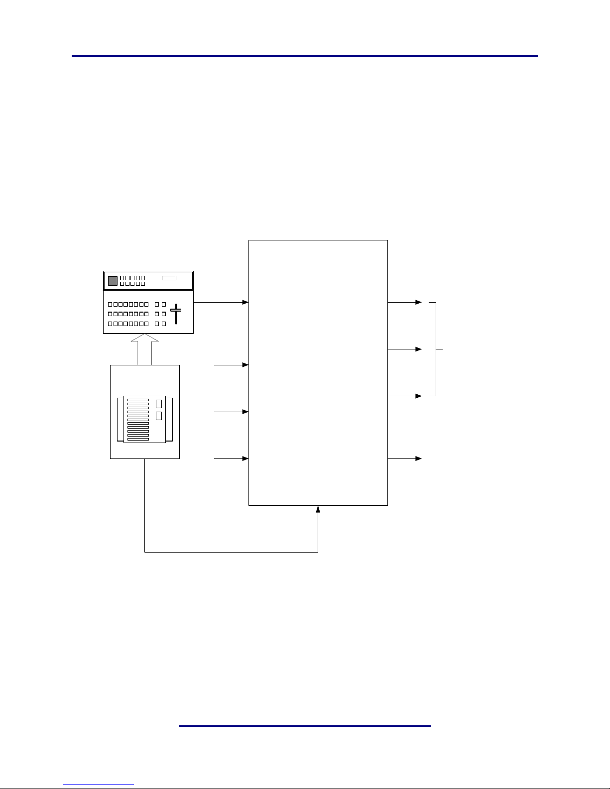
The first application is one where the UPMAX 2251 processes the stereo material allowing
it to fit nicely within a 5.1 channel program. Figure 3-1 shows this scenario.
Linear Acoustic
UP
MAX 2251
Two-Channel
Local Plant
X
X
X
Main Input
Lt/Rt
Mix Input
C/LFE
Mix Input
Ls/Rs
Mix Input
Lf/Rf
AES REF
IN
Main Out
Lf/Rf
Main Out
C/LFE
Main Out
Ls/Rs
Aux Out
Lt/Rt
5.1 Channel
Main Output
Two-Channel
Utility Output
Figure 3-1 UPMAX 2251 in a commercial upmixing application
Note that the two channel material is simply input to the UPMAX 2251 and a 5.1 channel
signal is available at the output. Either of the Commercial or Music presets can be chosen, and are explained in detail at the end of this chapter.
A similar situation can arrise when the Dolby E system is in use, and can actually help to
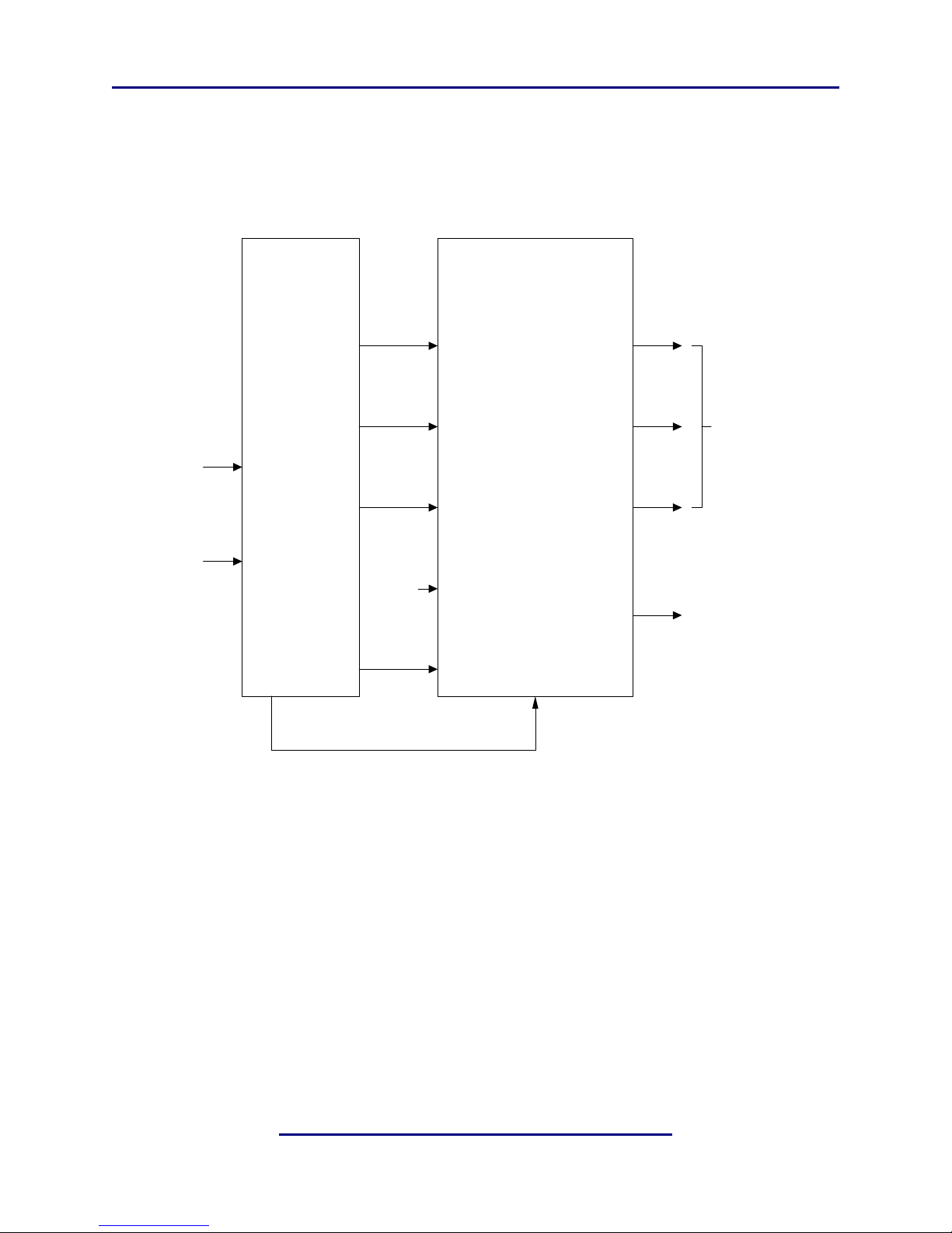
automate the process of turning the upmixing process on and off with no user intervention. The Status Port of a DP572 Dolby E Decoder provides a control signal that is logic
14
Page 17
Linear Acoustic upMAX 2251 User Guide Applications
high (1) when the DP572 is decoding Dolby E material, and is logic low (0) when two
channel PCM audio is being passed through. By connecting the DP572 Status Port to the
upMAX 2251 GPI input (A or B), the upmixing process will automatically be turned on
and off, and audio will be silently crossfaded between the two modes. Figure 3-2 shows
how this can be easily accomplished.
Dolby E
or
PCM
DP572
Dolby E Decoder
1/2
3/4
Main
Input
5/6
Vref
7/8
Status
(Pin 1,9)
Delay
Out
X
Linear Acoustic
Main Input
Lt/Rt
Mix Input
C/LFE
Mix Input
Ls/Rs
Mix Input
Lf/Rf
AES REF
IN
UP
MAX 2251
GPI A
(Pin 2, 15)
Main Out
Lf/Rf
Main Out
C/LFE
Main Out
Ls/Rs
Aux Out
Lt/Rt
5.1 Channel
Main Output
Two-Channel
Utility Output
Figure 3-2 UPMAX 2251 with Dolby DP572 Dolby E Decoder
The result is a clean, consistent 5.1 channel program that is discrete when Dolby E is
present and is upmixed when PCM is present, but with no audible change apparent to listeners or viewers. Note that while the upMAX 2251 AES Reference input is driven from
the PCM Delay Output of the DP572 for the sake of clarity in Figure 3-2, this is a perfectly
acceptable approach to use in practice.
15
Page 18
Linear Acoustic upMAX 2251 User Guide Applications
3.1.2 Sporting Events
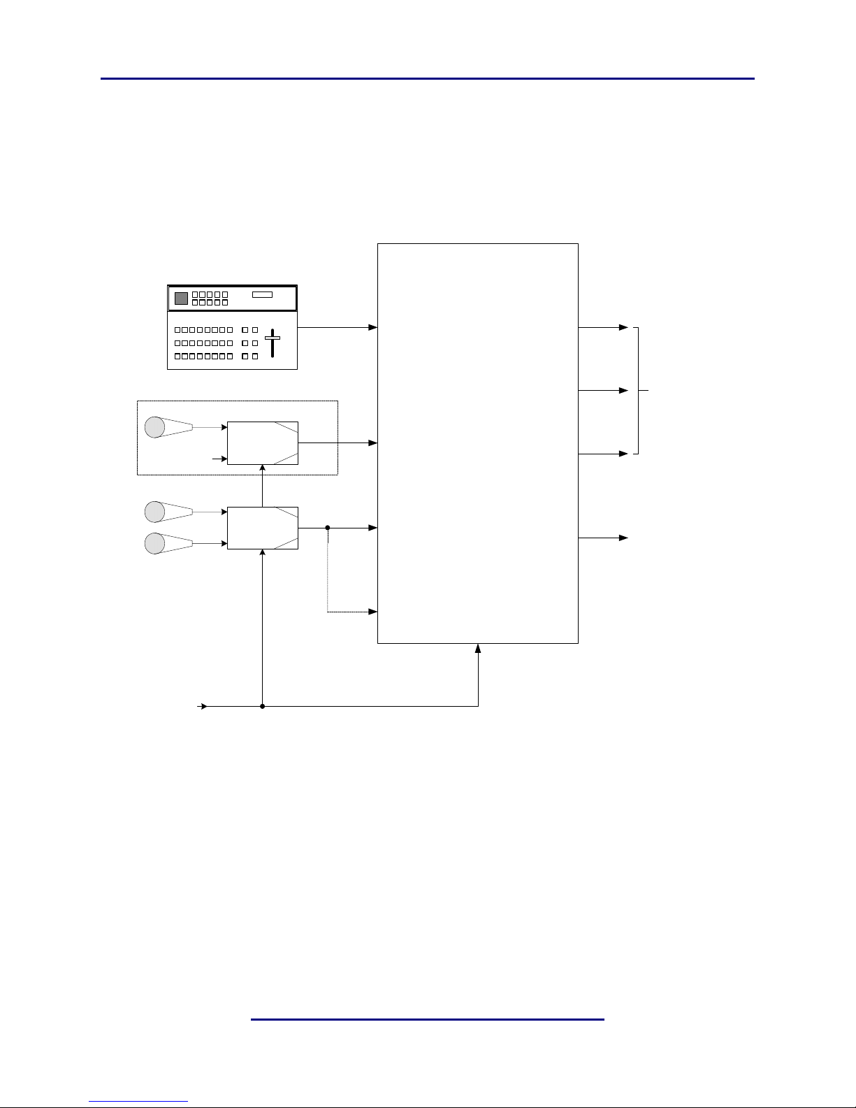
Figure 3-3 shows how a sporting event with a stereo mix, a stereo “natural” or ambience
mix, and an optional dry announcer mix can be easily combined into a very convincing 5.1channel program.
Two-Channel Mix
(LtRt or Stereo)
Announcer
Stereo
"Natural" Sound
LFE
Ls
Rs
C
X
A-to-D
Converter
A-to-D
Converter
(Optional)
(Optional)
Main Input
Lt/Rt
Mix Input
C/LFE
Mix Input
Ls/Rs
Mix Input
Lf/Rf
Linear Acoustic
UP
MAX 2251
AES REF
IN
Main Out
Lf/Rf
Main Out
C/LFE
Main Out
Ls/Rs
Aux Out
Lt/Rt
5.1 Channel
Main Output
Two-Channel
Utility Output
AES Ref
Figure 3-3 UPMAX 2251 in a live sports application
Note that if the announcer is already present in the main stereo mix (applied to the LtRt
Main Input), then no additional announcer input is required as it will automatically be upmixed into the Center channel output.
3.1.3 Music Awards-Type Events
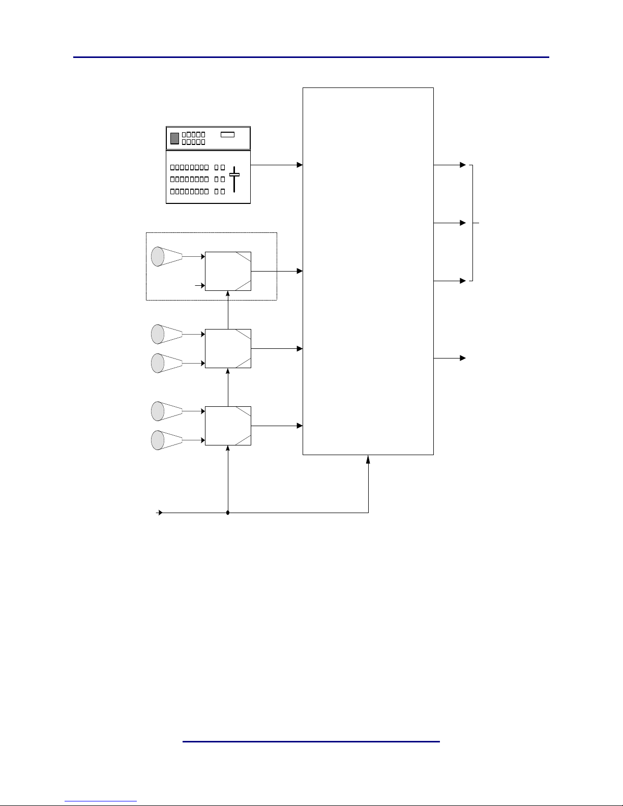
Figure 3-4 shows how a music awards-type program can be greatly simplified by the use of
UPMAX 2251. The main stereo or surround mix of the program is applied to the LtRt
an
Main Inputs, while crowd noise, reverb, ambience, and selective music cues are selectively
applied to the Ls/Rs and Lf/Rf Mix inputs. All announce microphones can be either part
of the main mix or applied as a separate feed to the Center Mix Input.
16
Page 19
Linear Acoustic upMAX 2251 User Guide Applications
Standard
Two-Channel Mix
(LtRt or Stereo)
Linear Acoustic
UP
MAX 2251
Crowd, Reverb,
Select Music
Select Music or
Background Vox
Announcer
LFE
Ls
Rs
Ls
Rs
C
X
A-to-D
Converter
A-to-D
Converter
A-to-D
Converter
(Optional)
Main Input
Lt/Rt
Mix Input
C/LFE
Mix Input
Ls/Rs
Mix Input
Lf/Rf
AES REF
IN
Main Out
Lf/Rf
Main Out
C/LFE
Main Out
Ls/Rs
Aux Out
Lt/Rt
5.1 Channel
Main Output
Two-Channel
Utility Output
AES Ref
Figure 3-4 UPMAX 2251 in a music awards-type program
3.2 Factory Presets
To get users up and running as quickly as possible, a few basic presets have been created
for different situations. The name of the game with this unit is “play”. There is no possible
way that presets appropriate for every situation could be generated, so we have included a
few to get you started. By all means, make adjustments, listen, store your new preset with
a name of your choice when you get it just right (we even have some Swedish characters
in there).
17
Page 20

Linear Acoustic upMAX 2251 User Guide Applications
The
UPMAX 2251 ships with the following factory presets:
• Reference Settings - Stock settings, a good place to start from scratch as all settings
are in a reasonable “detent” position. Start here if you are unsure.
• Music Cntr Spread - Straight two-channel to 5.1 channel upmixing, with the center
channel spread across the Left, Center, and Right outputs. This is very useful for programming that either contains dialogue with music or is just mono dialogue as it nicely
fills the front three channels, and feeds the surrounds when appropriate.
• MUSIC FULLCENTER - Again, straight two-channel to 5.1 channel upmixing, but
with the Center channel kept discrete. Useful for film mixes and certain music mixes.
Two-channel mono programs will be reproduced from the Center channel only.
• LIVE 4-CH to 5.1CH - Couples a straight two-channel to 5.1 channel upmix with ex-
ternal surround information applied to the Ls/Rs Mix Inputs. Useful for a sports mix
where a two-channel main program and a 2-channel natural or ambience mix are available.
• LIVE 4-CH and ANNOUNCE - Again, couples a straight two-channel to 5.1 chan-
nel upmix with external surround information applied to the Ls/Rs Mix Inputs, but
also allows an announcer to be mixed into the Center channel via the Center Mix Input.
• COMMERCIAL SHALLOW - Straight two-channel to 5.1 channel upmix with the
Surround audio positioned closer to the front channels. The Center channel is spread
by the standard 33%.
• COMMERCIAL DEEP - Straight two-channel to 5.1 channel upmix with the Surround audio positioned all the way to the back and the Center channel spread by the
standard 33%
18
Page 21
Linear Acoustic upMAX 2251 User Guide
Chapter 4: Menus
This chapter discusses how to use the front panel LCD interface to access the menus. Most
of it is rather obvious, and a bit of experimentation will quickly make you comfortable navigating through the submenus. If in doubt, use the Left Arrow to back out towards the
Main menu. The menus and submenus are structured to access more complex functionality as you go deeper into the hierarchy. Almost every important adjustment can be made
from the first three menu levels.
4.1 Main Menu
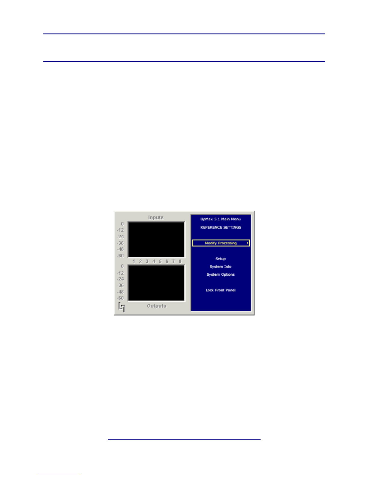
Figure 4-1 shows the main screen. The top eight meters show input activity for the Main
Input (Lt/Rt) and the Mix Inputs (C/LFE, Ls/Rs, Lf/Rf). The bottom eight meters show
the output activity for the Main AES Outputs (Lf/Rf, C/LFE, Ls/Rs, Lt/Rt). The submenus to the right of the meters are used to access the processor’s functions, which are
described in this chapter.
Figure 4-1 Main Screen showing level meters to the left and menus to the right.
4.1.1 Modify Processing Menu
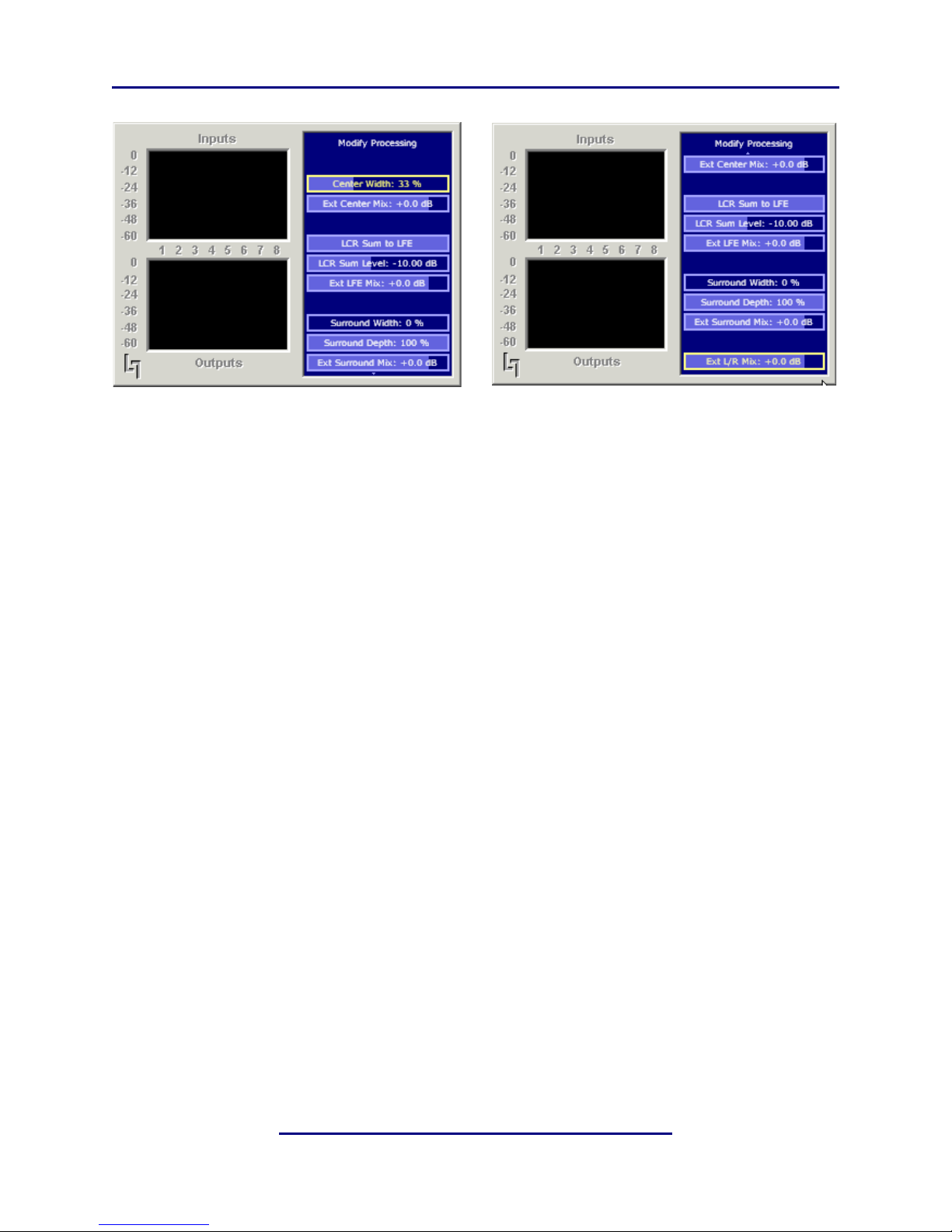
The Modify Processing menu controls all of the audio functions provided by the UPMAX
2251. As all of the settings do not fit onto one screen, it is necessary to scroll to the bottom
(using the Down Arrow). Figure 4-2 shows the selections available in the Modify Processing menu:
19
Page 22
Linear Acoustic upMAX 2251 User Guide Menus
Figure 4-2 Modify Processing menu; scroll down to access Ext L/R Mix (as shown on right menu)
The Modify Processing menu is broken into four major sections, Center channel con-
trols, Low Frequency Effects (LFE) channel controls, Surround controls, and Left Front/
Right Front (Lf/Rf) controls. Each section has specific controls for both the upmixer output signals (where appropriate) and for the external Mix Inputs. Note that the upmixer
controls have no effect on the external Mix Inputs, these input are kept fully discrete from
input to output. Below, each of the controls is presented with the default setting in bold:
Center:
• Center Width: controls how much of center channel output of the upmixer is spread
back into the Left and Right channel Main Outputs of the unit; Default 33%
• Ext Center Mix: controls how much attenuation is applied to the discrete external Center channel Mix Input is mixed into the Center channel Main Output; Default 0dB
LFE:
• LCR Sum to LFE: On/Off selection; Default On (highlighted)
• LCR Sum Level: controls how much of a 120Hz low pass filtered sum of the Left, Center, and Right outputs of the upmixer is fed to the LFE channel Main Output; Default
-10dB
•Ext LFE Mix: controls how much attenuation is applied to the discrete external LFE
channel Mix Input is mixed into the Center channel Main Output; Default 0dB
20
Page 23
Linear Acoustic upMAX 2251 User Guide Menus
Surround:
•Surround Width (not presently active): controls how much separation is produced between the Left Surround (Ls) and Right Surround (Rs) outputs of the upmixer, where
100% means maximum separation and 0% means minimum separation (i.e. mono);
Default: 0% (fixed)
•Surround Depth: controls back-to-front panning of the Surround output of the upmixer, where 100% equals full signal from the Left Surround and Right Surround Main
Outputs and 0% equals surround fully mixed back into the LCR outputs; Default:
100%
• Ext Surround Mix: controls how much attenuation is applied to the discrete external
Left and Right Surround channel Mix Inputs are mixed into the Left and Right Surround channel Main Outputs; Default 0dB
L/R:
• Ext L/R: controls how much attenuation is applied to the discrete external Left Front
and Right Front channel Mix Inputs are mixed into the Left and Right channel Main
Outputs; Default 0dB
4.1.2 Setup Menu
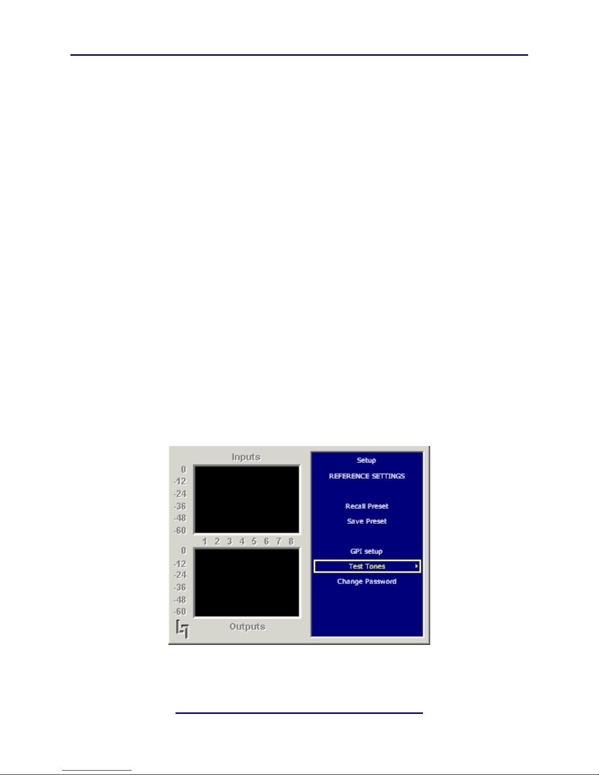
The Setup menu shows the current preset that the UPMAX 2251 is running and allows access to both recall other presets or store a modified preset:
Figure 4-3 Setup menu
21
Page 24

Linear Acoustic upMAX 2251 User Guide Menus
The Setup menu also allows for configuration of the GPI Inputs (currently not enabled),
selection of Test Tones for setup, as well as changing a password (if one has been set). Below are detailed descriptions of these submenus:
GPI Setup allows configuration of the GPI A and B inputs. Each can be set to provide a
specific function that will be active while the GPI pin (A or B) is held in a low state. When
GPI is enabled (the Enable GPI menu item is highlighted), the unit waits for an external
command via the GPI/O port and nothing else can be changed. To make a change to the
type of action each will produce, disable GPI by de-selecting the menu item. The available
functions include the following:
• Disable
• Upmix Off/On - Holding GPI low causes the upmixer to be activated. This mode is
useful when GPI A or B of the upMAX 2251 is being sourced from the Status Port of
a DP572 Dolby E Decoder as it will provide a constant 5.1 channel signal regardless
of whether the incoming signal is 5.1 channel Dolby E or PCM. See Section 3.1.1 for
more information.
• Upmix On/Off - Inverted operation of above; Holding GPI low causes the upmixer
to be de-activated
•Mute All Ext Inputs - Holding GPI low causes the Ext Center, LFE, Ls/Rs, and Lf/
Rf inputs to be muted.
• Mute Ext Center - Holding GPI low causes the External Center input to be muted
• Mute Ext LFE - Holding GPI low causes the External LFE input to be muted
• Mute Ext Surround - Holding GPI low causes the External Surround inputs to be
muted
• Mute Ext LfRf - Holding GPI low causes the External Left front and Right front inputs to be muted
Test Tones – Multiple setup tones are available to calibrate the upMAX 2251 and other
downstream equipment. The Level control is self-explanatory, but is set at the standard –
20 dBFS reference level and adjusts the overall level of the test signals. The available test
signals are:
• Sine – 1 kHz sine wave (frequency lower at lower sample rates)
• Voice – Voice ID of all selected channels
• Pink Noise – Equal energy-per-octave noise
22
Page 25
Linear Acoustic upMAX 2251 User Guide Menus
• White Noise – Equal level-per-octave noise
• Brown Noise – Low-pass-filtered noise
• Brown Nose – Try it (can’t be serious all the time- we’d crack)
• The last selection determines which channels will reproduce the selected test signals.
It can be adjusted by cycling through all channels, all channels of just the main program
(default), and individual channels.
Change Password – The password is either entered here for the first time or changed.
Use the rotary knob and the right arrow key to enter your password, then select Save. You
will be prompted several times, and then you will be reminded not to lose the password.
Please heed the warning! If you do happen to lose it, please call us to assist recovery without
losing presets. If you wish to remove the password, simply enter the old password, then
enter nothing for the new one and select Save. You will be prompted a few times, and then
it will be removed.
Save and Recall Preset – All configuration begins with a factory preset but these can be
modified, stored, and recalled.
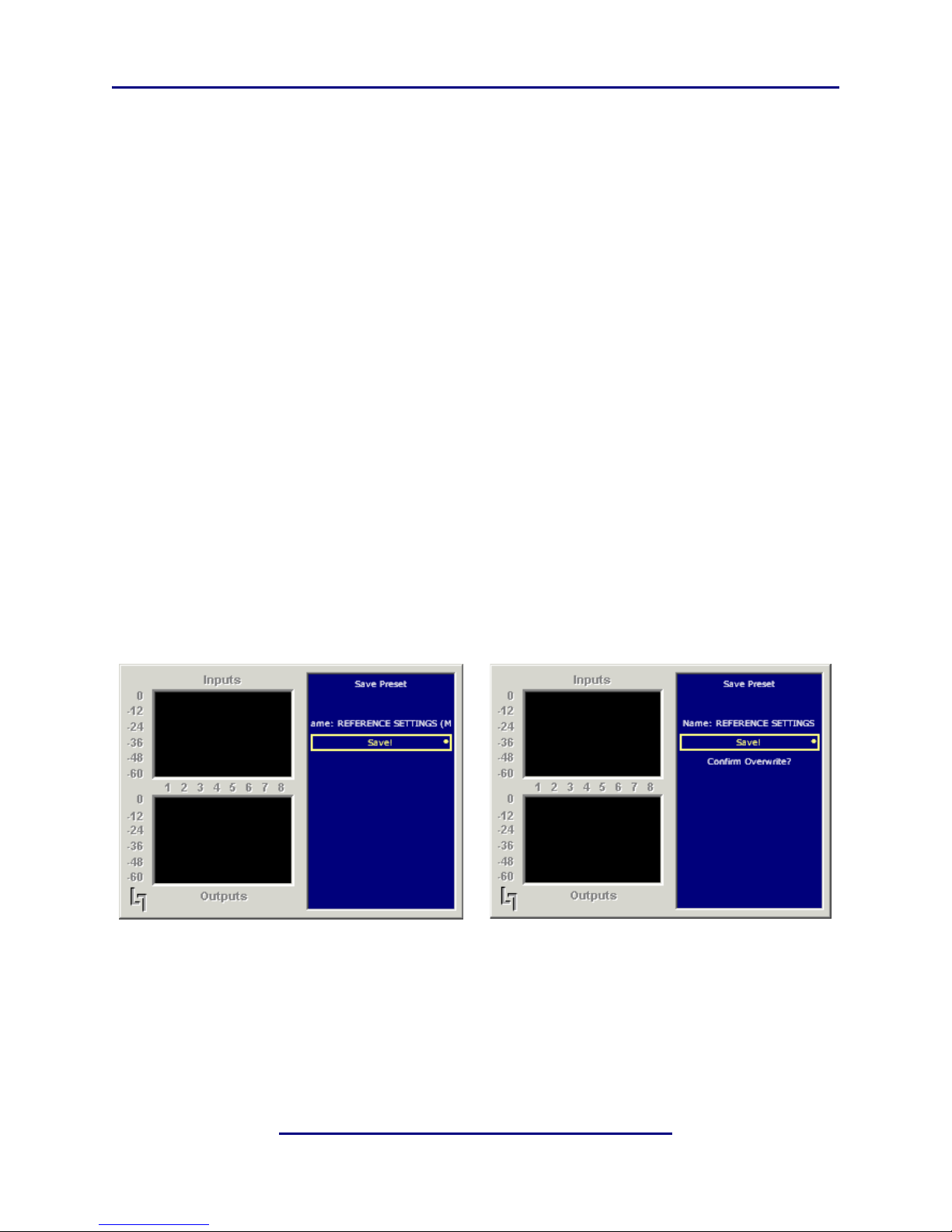
Saving a preset is a simple procedure. Adjusting any parameter in the Modify Processing
menu appends an M to the name of the original preset to indicate that it has been modified
but not yet saved yet. Figure 4-4 shows the Save Preset menu.
Figure 4-4 Save Preset menu before (left) and after (right) saving
The Save Preset screen allows you to keep the existing name or rename and save using
the arrow keys and the rotary encoder. If you remove the M and attempt to write over the
previously saved preset name, you will be prompted to confirm that you wish to overwrite
a stored preset.
23
Page 26

Linear Acoustic upMAX 2251 User Guide Menus
CAUTION:The system allows overwriting the factory stored presets, please rename!
4.1.3 System Info
The System Info menu provides the following statistics:
• Firmware Version
• CPU Usage – Normally around 20%
• Buffer Size
• Average SR – Average Sample Rate
• Samples Processed – This is a useless (but fun) statistic
4.1.4 System Options
The System Options menu provides the following functions:
• Master Bypass – Relay bypass of Digital Inputs to Digital Outputs
• LCD Shutoff – Select the time-out for the LCD backlight. The backlight turns on
once any control is pressed. The unit ships with a 15 minute setting to prolong the life
of the backlight tube. Although the unit is rated for long life, it will not last forever and
the entire costly LCD display must be replaced when it fails. We like the light show and
the meters and have not had a display fail in two years of almost constant use, but we
are being respectful of our customer’s budgets!
• Reinitialize – Fast reset of the system software and audio drivers
• Power Cycle – Slow reset of the entire system. Select this to perform a full system reboot and re-initialize; you are returned to the main menu.
4.1.5 Lock Front Panel
Select this menu to lock the front panel (funny enough).
24
Page 27

Linear Acoustic upMAX 2251 User Guide
Chapter 5: Specifications
Table 5-1 Electrical Specifications
Sampling Rate
Output Delay
Audio Word Length
Digital Audio In
Digital Audio Out
LtRt/Aux Output
Metadata Input
Metadata Output
GPIO Port
Ethernet Port
Analog Outputs
48 kHz (0.1%), 44.1 kHz (0.1%)
14 ms (min.), optional one video frame (PAL or NTSC)
Up to 24 bits
Five BNC female connectors, AES-3ID-1995/SMPTE 276M
Four BNC female connectors, AES-3ID-1995/SMPTE 276M
25-pin female D-connector, +4 dBu balanced (LtRt output
only)
RS-485, 9-pin female D-connector on rear panel
RS-485, 9-pin female D-connector on rear panel
TTL level, 25-pin female D-connector
RJ-45 female jack connector
Frequency Response
Distortion
Dynamic Range
Output Connectors
Digital I/O
Digital Audio Inputs
Digital Audio Outputs
REF Input
20 Hz–20 kHz, 0.5 dB
Less than 0.01% at 1 kHz
Less than 0.02%, 20 Hz–20 kHz
Greater than 106 dB
LtRt/Aux Output via 25-pin female D-connector
Four unbalanced female BNC connectors compatible with
AES-3ID-1995/SMPTE 276M specifications.
Four unbalanced female BNC connectors compatible with
AES-3ID-1995/SMPTE 276M specifications.
One unbalanced female BNC connectors compatible with AES3ID-1995/SMPTE 276M specifications.
25
Page 28

Linear Acoustic upMAX 2251 User Guide Specifications
Table 5-2 Mechanical Specifications
Dimensions
Net Weight
Shipping Weight
Power Requirements
Power Consumption
Table 5-3 Environmental Specifications
Operating Temperature
Non Operating Temperature
(Storage)
Humidity
EMC Radiation Limits
5.25 19 24 in (13.3 48.3 61 cm)
25 lb (12.6 kg) approx.
32 lb (15.75 kg) approx.
115/220 VAC, switchable, 50–60 Hz
40 W maximum
0oC to 50oC, fan cooled
o
–20
C to +70oC
Up to 98% relative humidity, non-condensing
FCC Part 15 Class A, ICES-003
26
Page 29

Linear Acoustic upMAX 2251 User Guide Specifications
Metadata Input Port
9-pin female D-connector with full-duplex RS-485 protocol running at 115 kbps. Pinout
is compatible with SMPTE 207M.
Table 5-4 Metadata Input Port Pinout
Pin Connection
1Shield
2TX A asynchronous data out –
3RX B asynchronous data in +
4Ground
5NC
6Ground
7TX B asynchronous data out +
8RX A asynchronous data in –
9Shield
Metadata Output Port
9-pin female, RS-485, full-duplex, 115 kbps. Pinout is compatible with SMPTE 207M.
Table 5-5 Metadata Output Port Pinout
1 Shield
2RX A asynchronous data in –
3TX B asynchronous data out +
4Ground
5NC
6Ground
Pin Connection
7RX B asynchronous data in +
8TX A asynchronous data out –
9 Shield
27
Page 30

Linear Acoustic upMAX 2251 User Guide Specifications
Ethernet Port
The Ethernet port is a standard RJ-45 female connector that supports 10 or 100BASE-T.
GPI/O Parallel Control Port
TTL level controls, active Low. GPI A and B are held low to activate their assigned function, while GPI 1-6 require momentary contact to ground to activate their functions. The
5-V output for external GPO indicators is limited by a self-resetting fuse.
Table 5-6 GPI/O Parallel Control Port Pinout
Pin Function Pin Function
1+ 5 V (150 mA) 14 + 5 V (150 mA)
2GPI A (Hold Low=On)15 Ground
3GPI B (Hold Low=On)16 Ground
4GPI 1 (Momentary) 17 Ground
5GPI 2 (Momentary) 18 Ground
6GPI 3 (Momentary) 19 Ground
7GPI 4 (Momentary) 20 Ground
8GPI 5 (Momentary) 21 Ground
9GPI 6 (Momentary) 22 Ground
10 No Connection 23 Ground
11 No Connection 24 GPO 1
12 GPO 2 25 Ground
13 Ground
28
Page 31

Linear Acoustic upMAX 2251 User Guide Specifications
Lt/Rt + 7/8 Analog Output
25-pin female D-connector. Uses similar pinout as DA-88 connector except that channel
4 has been replaced by an unbalanced AES digital output, and channels 2, 5, and 6 are not
used.
Table 5-7 Lt/Rt + 7/8 Analog Output Pinout
Pin Connection Pin Connection
1Rt + Out 14Rt – Out
2Rt Ground 15Lt + Out
3Lt – Out 16Lt Ground
4No Connection 17No Connection
5 RESERVED 18 RESERVED
6No Connection 19No Connection
7No Connection 20No Connection
8No Connection 21No Connection
9No Connection 22No Connection
10 No Connection 23 No Connection
11 No Connection 24 No Connection
12 No Connection 25 No Connection
13 No Connection
29
Page 32

Linear Acoustic upMAX 2251 User Guide Specifications
30
 Loading...