

Page 1
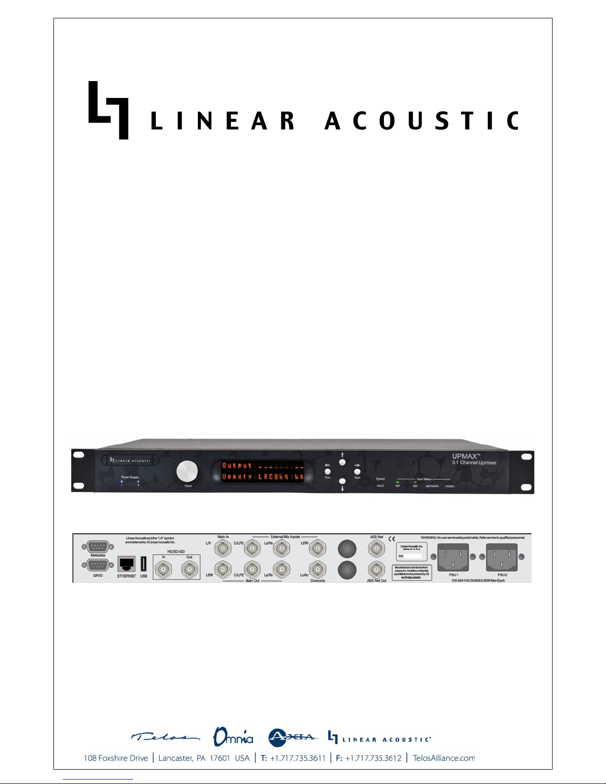
UPMAX
5.1-Channel Reference Upmixer
User Guide
Release Date: June 2013
Software Version: 0.98 and later
Linear Acoustic Inc.
Phone: 717-735-3611
FAX: 717-735-3612
Web: www.LinearAcoustic.com
Page 2

Warranty Information
DISCLAIMER OF WARRANTIES: Products manufactured by Linear Acoustic are warranted
against defects in material and workmanship for a period of two (2) years from the date of purchase.
THERE ARE NO OTHER IMPLIED OR EXPRESS WARRANTIES AND NO WARRANTY FOR MERCHANTABILITY OR FITNESS FOR A PARTICULAR PURPOSE.
During the warranty period Linear Acoustic Inc. will repair, or at our discretion replace, components
which prove to be defective, provided the unit is returned, shipped pre-paid to us directly with a return
authorization (RA) number clearly marked on the packaging. Please note, this RA number must be
present or package will be refused and returned to sender.
All requests for repairs MUST include the unit serial number to ensure quick and accurate service.
DEFECTS CAUSED BY UNAUTHORIZED MODIFICATIONS, MISUSE OR ACCIDENTS, UNAUTHORIZED CUSTOMER REPAIRS, OR ANY FURTHER DAMAGE
CAUSED BY INADEQUATE PACKAGING FOR SERVICE RETURN ARE NOT COVERED BY THIS WARRANTY.
PLEASE SAVE THE SHIPPING CARTON AND ALL PACKING MATERIALS. FAILURE
TO RETURN UNIT IN ORIGINAL SHIPPING CARTON AND PACKING MATERIALS
WILL RESULT IN A CHARGE FOR NEW SHIPPING MATERIALS.
LIMITATION OF PERIOD OF ACTION ON CONTRACT: No action, regardless of form,
arising out of the transactions under this agreement may be brought by buyer, its successors, agents
and/or assigns, more than three years from date of purchase.
LIMITATION OF LIABILITY: It is understood and agreed that Linear Acoustic’s liability whether
in contract, in tort, under any warranty, in negligence or otherwise shall not exceed the cost of repair
or replacement of the defective components and under no circumstances shall Linear Acoustic be liable
for incidental, special, direct, indirect or consequential damages, or loss of use, revenue or profit even
if Linear Acoustic or its agents have been advised, orally or in writing, of the possibility of such damages.
This product contains Audyne technology and is manufactured under license.
Linear Acoustic, the “LA” symbol, UPMAX, AEROMAX, AERO.100, AERO.air, AutoNorm, MetaMAX, AutoMAX-II, AutoVoiceover, AutoVOX, AutoSAP, and CrowdControl, are trademarks or
registered trademarks of Linear Acoustic Inc., all other trademarks remain the property of their respective owners.
Page 3
Regulatory Notices and Fusing Information
FCC
This equipment has been tested and found to comply with the limits for a Class A digital device,
pursuant to Part 15 of the FCC Rules. These limits are designed to provide reasonable protection
against harmful interference when the equipment is operated in a commercial environment. This
equipment generates, uses, and can radiate radio frequency energy and, if not installed and used in
accordance with this instruction manual, may cause harmful interference to radio communications.
Operation of this equipment in a residential area is likely to cause harmful interference in which case
the user will be required to correct the interference at his or her own expense.
Canada
This Class A digital apparatus complies with Canadian ICES-003.
UL
WARNING: Troubleshooting must be performed by a trained technician. Do not
attempt to service this equipment unless you are qualified to do so.
Check that the correct fuses have been installed. To reduce the risk of fire, replace
only with fuses of the same type and rating.
Exposed portions of the power supply assembly are electrically “hot”. In order to reduce the risk
of electrical shock, the power cord MUST be disconnected when the power supply assembly is
removed.
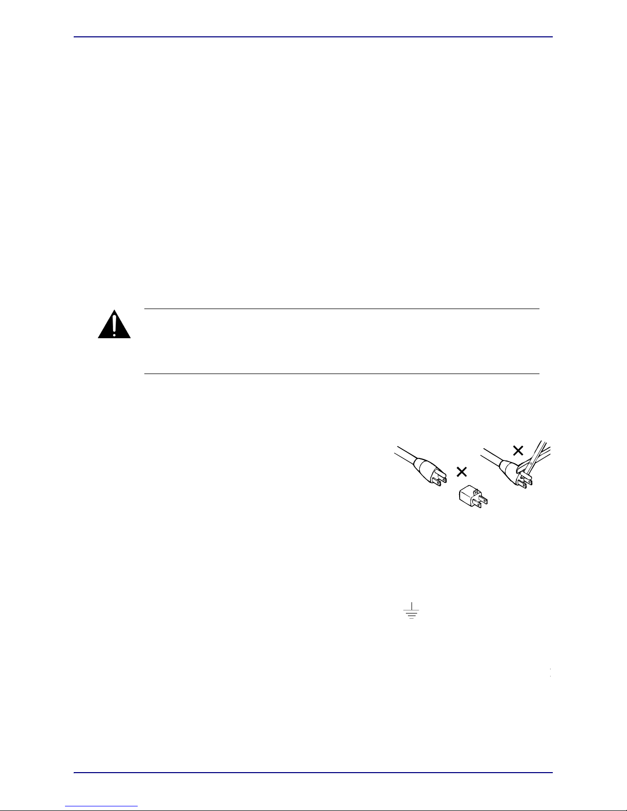
The ground terminal of the power plug is connected
directly to the chassis of the unit. For continued protection
against electric shock, a correctly wired and grounded
(earthed) three-pin power outlet must be used. Do not use
a ground-lifting adapter and never cut the ground pin on
the three-prong plug.
UK
As the colours of the cores in the mains lead may not correspond with the coloured markings
identifying the terminals in your plug, proceed as follows:
x The core that is coloured green and yellow must be connected to the terminal in the
plug identified by the letter E or by the earth symbol
or coloured green or green
and yellow.
x The core that is coloured blue must be connected to the terminal that is marked with t
letter N or coloured black.
x The core that is coloured brown must be connected to the terminal that is marked with
the letter L or coloured red.
x This apparatus must be earthed.
Page 4

s equipment complies with the EMC requirements of EN55103-1 and EN55103-2 when operated in an E2 environment
IMPORTANT SAFETY NOTICE
unit complies with the safety standard EN60065. The unit shall not be exposed to dripping or splashing and no objects filled with liquids, such as
Ensure that your mains supply is in the correct range for the input power requirement of the unit.
Ensure fuses fitted are the correct rating and type as marked on the unit.
The unit must be earthed by connecting to a correctly wired and earthed power outlet.
The power cord supplied with this unit must be wired as follows:
Live—Brown Neutral—Blue Earth—Green/Yellow
IMPORTANT – NOTE DE SECURITE
choc électrique ou tout risque d'incendie, veillez à observer les recommandations suivantes.
Le selecteur de tension doit être placé sur la valeur correspondante à votre alimentation réseau.
Les fusibles doivent correspondre à la valeur indiquée sur le materiel.
Le materiel doit être correctement relié à la terre.
Le cordon secteur livré avec le materiel doit être cablé de la manière suivante:
Phase—Brun Neutre—Bleu Terre—Vert/Jaune
WICHTIGER SICHERHEITSHINWEIS
e Gefäße, z.B. Kaffeetassen, auf das Gerät. Für das sichere Funktionieren des Gerätes und zur Unfallverhütung (elektrischer Schlag, Feuer) sind die
Der Spannungswähler muß auf Ihre Netzspannung eingestellt sein.
Die Sicherungen müssen in Typ und Stromwert mit den Angaben auf dem Gerät übereinstimmen.
Die Erdung des Gerätes muß über eine geerdete Steckdose gewährleistet sein.
Das mitgelieferte Netzkabel muß wie folgt verdrahtet werden:
Phase—braun Nulleiter—blau Erde—grün/gelb
NORME DI SICUREZZA – IMPORTANTE
Assicurarsi che il selettore di cambio tensione sia posizionato sul valore corretto.
Assicurarsi che la portata ed il tipo di fusibili siano quelli prescritti dalla casa costruttrice.
L'apparecchiatura deve avere un collegamento di messa a terra ben eseguito; anche la connessione rete deve
avere un collegamento a terra.
Il cavo di alimentazione a corredo dell'apparecchiatura deve essere collegato come segue:
Filo tensione—Marrone Neutro—Blu Massa—Verde/Giallo
AVISO IMPORTANTE DE SEGURIDAD
unidad cumple con la norma de seguridad EN60065. La unidad no debe ser expuesta a goteos o salpicaduras y no deben colocarse sobre el equipo
Asegúrese que el selector de tensión esté ajustado a la tensión correcta para su alimentación.
Asegúrese que los fusibles colocados son del tipo y valor correctos, tal como se marca en la unidad.
La unidad debe ser puesta a tierra, conectándola a un conector de red correctamente cableado y puesto a tierra.
El cable de red suministrado con esta unidad, debe ser cableado como sigue:
Vivo—Marrón Neutro—Azul Tierra—Verde/Amarillo
VIKTIGA SÄKERHETSÅTGÄRDER!
Kontrollera att spänningsväljaren är inställd på korrekt nätspänning.
Konrollera att säkringarna är av rätt typ och för rätt strömstyrka så som anvisningarna på enheten föreskriver.
Enheten måste vara jordad genom anslutning till ett korrekt kopplat och jordat el-uttag.
El-sladden som medföljer denna enhet måste kopplas enligt foljande:
Fas—Brun Neutral—Blå Jord—Grön/Gul
BELANGRIJK VEILIGHEIDS-VOORSCHRIFT:
Controleer of de spanningscaroussel op het juiste Voltage staat.
Gebruik alleen zekeringen van de aangegeven typen en waarden.
Aansluiting van de unit alleen aan een geaarde wandcontactdoos.
De netkabel die met de unit wordt geleverd, moet als volgt worden aangesloten:
Fase—Bruin Nul—Blauw Aarde—Groen/Geel
F
E
NL
S
I
D
GB
Page 5
Fusing Information
WARNING: To reduce the risk of fire, replace fuses only with the same type
and rating.
Both units use a universal switching power supply that handles the full range of
nominal mains voltages between 90 and 264 VAC and any frequency between 50 Hz
and 60 Hz.
Check Main Fuse
The Main fuse rating is:
T 1A L (1 Amp, 250 V, 20 mm, time-lag, low breaking capacity) for all operating
voltages.
WARNING: The power to the unit must be off when the following steps are
p
erformed. Ensure that the main power cable to the unit is not connected to a
p
ower source.
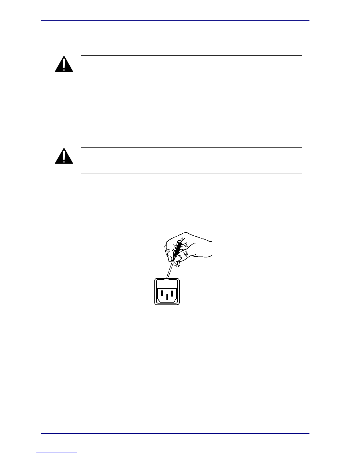
1. Open the fuse compartment door in the AC power input housing with a small flatblade screwdriver (Figure 1). Carefully pull out the fuse carrier.
2. Check that the replacement fuse has the correct rating. The fuse carrier must be
inserted into the compartment carefully. Do not force the carrier into the
compartment or both could be damaged.
3. Snap the fuse compartment door closed.
Figure 1 Checking the Main Fuse
Internal Fuse
The switching power supply contains a separate fuse. Most fault conditions should be
protected by the main fuse.
If you find it necessary to replace the internal fuse, be certain to replace it with a fuse
of the same type and rating as printed on the switching power supply board.
Page 6

Page 7

Linear Acoustic UPMAX User Guide
Table of Contents
List of Figures..........................................................................................................................................3
Chapter 1: Introduction.................................................................................................................5
1.1 Principles of Operation..........................................................................................5
1.2 Warranty and Feedback .........................................................................................7
Chapter 2: Connections and Quick Setup.....................................................................9
2.1 Unpacking and Inspection ....................................................................................9
2.2 Installation ...............................................................................................................9
2.3 Rear Panel ..............................................................................................................10
2.3.1 Connection Ports .................................................................................10
2.4 Quick Setup Notes ...............................................................................................11
Chapter 3: Applications..............................................................................................................13
3.1 Typical Scenarios ..................................................................................................13
3.1.1 Two-Channel Commercials and Interstitial Programming............14
3.2 Factory Presets ......................................................................................................16
Chapter 4: Detailed Operation...............................................................................................17
4.1 Menu Navigation ..................................................................................................17
4.1.1 Output and Upmix Status ...................................................................17
4.1.2 Statistics .................................................................................................17
4.1.3 UPMAX Setup......................................................................................17
4.1.4 I/O Menu..............................................................................................18
4.1.5 Communication ....................................................................................19
4.1.6 System ....................................................................................................19
1
Page 8

Linear Acoustic UPMAX User Guide
Chapter 5: Troubleshooting....................................................................................................23
5.1 Problems and Possible Causes............................................................................23
5.1.1 Unit won’t power on............................................................................23
5.1.2 Output Audio Clicks and Pops ..........................................................23
5.1.3 Unit is Not Upmixing..........................................................................24
5.1.4 Cannot Manually Control Upmixing.................................................24
Chapter 6: Specifications..........................................................................................................25
2
Page 9

Linear Acoustic UPMAX User Guide
List of Figures
1-1 Audio Block Diagram .........................................................................................................................6
2-1 Rear Panel ...........................................................................................................................................10
3-1 UPMAX in a commercial upmixing application ...........................................................................14
3-2 UPMAX with Dolby DP572 Dolby E Decoder ...........................................................................15
6-1 Electrical .............................................................................................................................................25
3
Page 10

Linear Acoustic UPMAX User Guide
4
Page 11

Linear Acoustic UPMAX User Guide
Chapter 1: Introduction
The Linear Acoustic UPMAX produces a 5.1 channel audio signal that is perfect for eventual transmission via Dolby Digital (also known as AC-3) to all consumers. The unit accepts a 2-channel input and “upmixes” it to fill as many of the 5.1 output channels as the
user selects. Any input signal from mono to LtRt (Left Total/Right Total) surround encoded audio can be applied to the Main Input and an output will be produced that maintains consistency with other 5.1 channel programming.
The UPMAX provides the following features:
• Advanced upmixing algorithm for stable, convincing surround experience.
• The only Upmixer fully downmix compatible with Dolby Digital (AC-3).
• Upmixed surround field is infinitely adjustable.
• External inputs allow crossfaded bypassing of upmixing to enable discrete 5.1 channel
audio to automatically pass untouched.
• Built-in independent LoRo/LtRt encoder
• Relay bypassed digital inputs for “mission critical” broadcast applications.
• Dual redundant auto-ranging power supplies
1.1 Principles of Operation
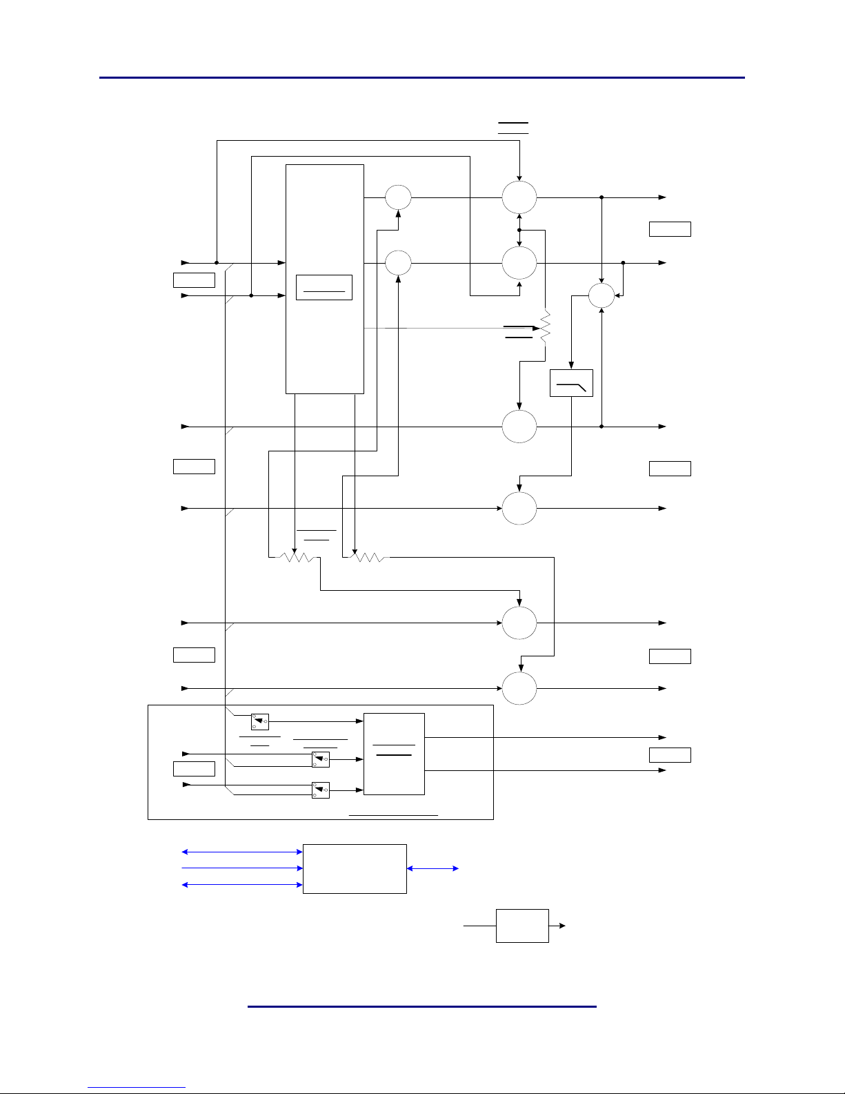
The UPMAX contains two paths for audio signals. The first path contains an upmixer, a
bass extension filter to create the LFE (Low Frequency Effects) or subwoofer channel, and
a simple but powerful set of mix controls to vary each element of the surroundfield. The
second path provides discrete inputs for the Center, LFE, Ls (Left Surround), Rs (Right
Surround), Lf (Left Front) and Rf (Right Front) channels. The upmixed and discrete outputs can be crossfaded between to allow smooth transitions between upmixed and discrete
audio.
Please refer to Figure 1-1. It should be noted that this diagram is a general representation
of signal flow. Please consult the appropriate section of this manual for an accurate description of actual functionality.
5
Page 12
Linear Acoustic UPMAX User Guide Introduction
Main In
Lt/Lo
Left
Center
Right
UPMAX
Surroun d
+
+
Byp In
Center
Center
Width
80 Hz
+
Byp In
LFE
+
+
Byp In
Ls
Byp In
Rs
Surround
Depth
Main
Out Rs
Main
Out Ls
Main
Out LFE
Main
Out C
Main
Out Rf
Main
Out Lf
Main In
Rt/Ro
Lf
Rf
Main Out
Lo/Lt
1/2 In
3/4 In
5/6 In
7/8 In
7/8 Out
5/6 Out
3/4 Out
1/2 Out
+
+
+
+
Upmix
On/Off
0% 100%
C,LFE,Ls,Rs
LoRo/LtRt
Encoder
Lf/Lt
Rf/Rt
Enc. Lf/Rf src=
1/2 or 7/8
Main Out
Ro/Rt
DOWNMIX ENCODER
0%
100%
Upmix On=
Mute
CPU
(FPUI, I/ O , PSU Mon,
System Control)
PSU
100-240
50/60Hz
PS
Mon
GPIO
Metadata
ETHERNET
Ctrl
Figure 1-1 Audio Block Diagram
6
Page 13

Linear Acoustic UPMAX User Guide Introduction
1.2 Warranty and Feedback
Please take a moment to fill out the postage-paid warranty card included with the unit and
drop it in the mail. This will enable us to contact you if there are any software or documentation issues. Also, we are very interested in your feedback. This unit was designed based
on input gathered from many broadcast engineers and it will evolve further thanks to ongoing suggestions and comments from users.
We look forward to hearing from you!
7
Page 14

Linear Acoustic UPMAX User Guide Introduction
8
Page 15

Linear Acoustic UPMAX User Guide
Chapter 2: Connections and Quick Setup
This chapter covers all required connections for the UPMAX.
2.1 Unpacking and Inspection
Before unpacking the unit, inspect the outer carton for shipping damage. If the carton
shows damage, inspect the unit in those areas. Please save the carefully designed shipping
carton and packing materials. In the unlikely event that the unit needs to be returned to the
factory, alternate cartons or packing materials may not be adequate and can cause damage
not covered by warranty.
The following essential items are provided with the unit:
• Bag containing:
• Quick-start sheet to get you up and running
• Two IEC power cords (style matches country of order);
• this manual, and a handy black pen.
• Warranty information: Please fill out and return the warranty card to Linear Acoustic
to ensure your software and documentation are kept up to date.
2.2 Installation
UPMAX installation requires:
• One standard rack space unit with ADEQUATE VENTILATION (the unit relies on
convection cooling from side-panel vents);
• standard 75-Ohm BNC cables for digital signal connections;
To connect to digital equipment with 110-Ohm XLR connectors, use impedancematching transformers (available from Canare, Neutrik and other manufacturers).
• Proper reference. The unit will default to internal 48kHz with no signals applied, but
either AES 1/2 or 3/4 can be used as the reference. For proper plant timing, it is
strongly recommend that one of these two AES inputs be supplied with a 48kHz AES
signal and used for reference.
9
Page 16
Linear Acoustic UPMAX User Guide Connections and Quick Setup
2.3 Rear Panel
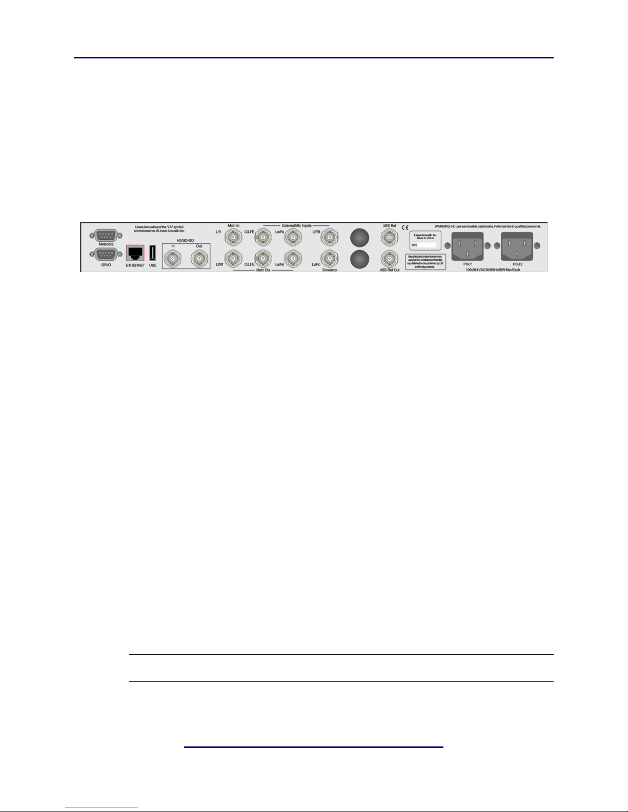
The rear panel of the UPMAX contains its electrical I/O.
2.3.1 Connection Ports
All UPMAX connections are on the rear panel and are described in detail below. See Chapter 5: Specifications for specific pinouts.
Figure 2-1 Rear Panel
• Metadata I/O: RS-485 connection accepts the metadata output of any Dolby equipment (DP572, DP570, etc...) or any Dolby-compatible metadata source. Used to control upmixing and other functions.
• SDI Input/SDI Output: Allows access to all 16 audio channels for HD and SD-SDI
embedding and de-embedding.
• GPI/O: Connect dry contact closures here to control upmixing on/off. Note that
GPI functions require held closures for the duration of the desired function. Status of
upmixing will be reflected on the corresponding GPO pin.
• ETHERNET: Used for firmware upgrades.
• Main Audio Input (1/2): Connect the two channel source for upmixing to this input.
In many cases the first pair of a 5.1 channel signal (LfRf) is also the stereo signal that
needs to be upmixed (L/R).
• External Mix Inputs (3/4 and 5/6): Audio from C/LFE and Ls/Rs applied to these
connectors will be passed through when upmixing is disabled, allowing a 5.1 channel
program to pass through 1/2, 3/4 and 5/6. In parallel, these inputs also feed the LoRo
encoder, with Left Front/Right Front from 7/8, allowing simultaneous encoding and
upmixing of a single or different programs.
NOTE: Appropriate reference should be applied to Input 1/2 for proper operation.
• Main Audio Outputs: Main 48kHz processed digital audio outputs. 1/2 = Left
Front/Right Front, 3/4 = Center/LFE, 5/6 = Left Surround/Right Surround.
10
Page 17

Linear Acoustic UPMAX User Guide Connections and Quick Setup
• Downmix Output: An LoRo or LtRt encoded version of the main inputs (Ch. 1-6) is
available from this connector at all times. Optionally, the LfRf source can come from
7/8 to allow separate upmixing and downmixing (see I/O Settings)
2.4 Quick Setup Notes
The Linear Acoustic UPMAX is configured at the factory and is ready to go on the air after
making the proper input and output connections and determining if upmixing is desired.
• Apply a two channel (stereo or LtRt) signal to Main Input 1/2
• The Reference and Main Input front panel indicators should be green.
• The main menu will default to showing output meters, and you should see activity on
some or all of the first six meters.
• Upmixed audio will be output from the Main Out 1-6 AES outputs in the following
format: 1/2 = Left Front/Right Front, 3/4 = Center/LFE, 5/6 = Left Surround/
Right Surround
• Note that 7/8 is the downmix output and will show activity and produce output only
when signals are applied to the LoRo/LtRt encoder inputs.
The best way to learn the processor is to explore the different settings with audio applied
and monitored. There are several factory presets to support many different tastes. Some
presets may not sound much different at first, but will perform very depending on program
content. When in doubt, try turning the upmixing process off or as a last resort use the
Master Bypass feature which will remove the UPMAX completely from the signal path.
11
Page 18

Linear Acoustic UPMAX User Guide Connections and Quick Setup
12
Page 19

Linear Acoustic UPMAX User Guide
Chapter 3: Applications
The UPMAX is intended to be used either in the production or distribution stages of 5.1
channel programming, and also selectively in transmission environments. For transmission
applications such as at DTV stations, the Linear Acoustic AERO line of products may be
more appropriate as they also contain requisite loudness processing and additional useful
features such as voiceover and EAS insertion.
The Linear Acoustic UPMAX is
mix (if one is available), however it
That being said, the UPMAX is an excellent tool useful in either creating a 5.1 channel version of a program when few or no other elements exist, and also for creating a solid foundation for a true discrete multichannel mix.
This chapter discusses several applications of the UPMAX:
• Integrating 2-channel commercials into a 5.1 channel program
• Creating a 5.1 channel sports program from stereo plus natural sources
• Use for music programming
• Discussion of presets stored in the unit
3.1 Typical Scenarios
Below are some application examples to give users some guidance in real-world situations.
However, before continuing, it is absolutely imperative that a proper multichannel monitoring environment be set up and calibrated before every mix. If the mix cannot be heard
properly, then it cannot be created properly. Users are advised to obtain copies of ATSC
A/85 (www.atsc.org/standards) for detailed, accurate information on modern monitoring
practices.
not
a substitute for a good, discrete multichannel
is
a useful tool to help create one.
The Linear Acoustic
ated. From hands-on adjust-as-you-go environments like a music awards program to setand-forget applications like helping two-channel commercials fit into 5.1-channel programming, the UPMAX is the answer.
UPMAX is useful almost anywhere a multichannel mix must be cre-
13
Page 20
Linear Acoustic UPMAX User Guide Applications
Linear Acoustic
UPMAX
M ain In p u t
L t/R t
(R E F)
Byp/Enc
In p u t
C/LFE
Byp/Enc
Inpu t
Ls/Rs
X
X
Main Out
Lf/Rf
Main Out
C/LFE
Main Out
Ls/Rs
Encoder
Out
LoRo/LtR t
5.1 Chann el
Main Output
Two-Channel
U tilit y Out p u t
Two-Channel
Local Plant
Byp/Enc
In p u t
Lf/Rf
X
3.1.1 Two-Channel Commercials and Interstitial Programming
One of the largest complaints viewers of digital and high definition television programming is the annoying fact that stereo commercials don’t seem to “fit” into the 5.1-channel
program. This is because in many cases, the commercials are simply transmitted on the
Left and Right channels of a 5.1-channel program. The net result is that during the program, dialogue comes from the center speaker, but at commercial or station breaks, all of
the dialogue comes from the left and right speakers. It can be a jarring experience.
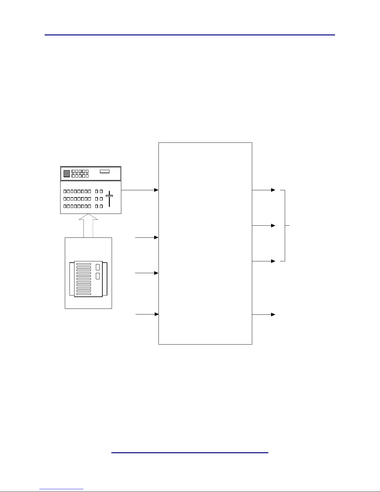
The first application is one where the UPMAX 2251 processes the stereo material allowing
it to fit nicely within a 5.1 channel program. Figure 3-1 shows this scenario.
Figure 3-1 UPMAX in a commercial upmixing application
Note that the two channel material is simply input to the UPMAX and a 5.1 channel signal
is available at the output. Either of the Commercial or Music presets can be chosen, and
are explained in detail at the end of this chapter.
14
Page 21
Linear Acoustic UPMAX User Guide Applications
Linear Acoustic
UPMAX
Main Input
Lt/Rt
(RE F)
Byp/Enc
Input
C/LFE
Byp/Enc
Input
Ls/Rs
Encode
Input
Lf/Rf
X
Main Out
Lf/R f
Main Out
C/LFE
Main Out
Ls/Rs
Encoder
Out
LoRo/LtRt
5.1 Channel
Ma in Outp ut
Two-Channel
Utilit y O u t p u t
DP572
Dolby E
Decoder
1/2
3/4
5/6
7/8
Delay
Out
Metadata
Metadata
Dolby E
or
PCM
Main
Input
Vref
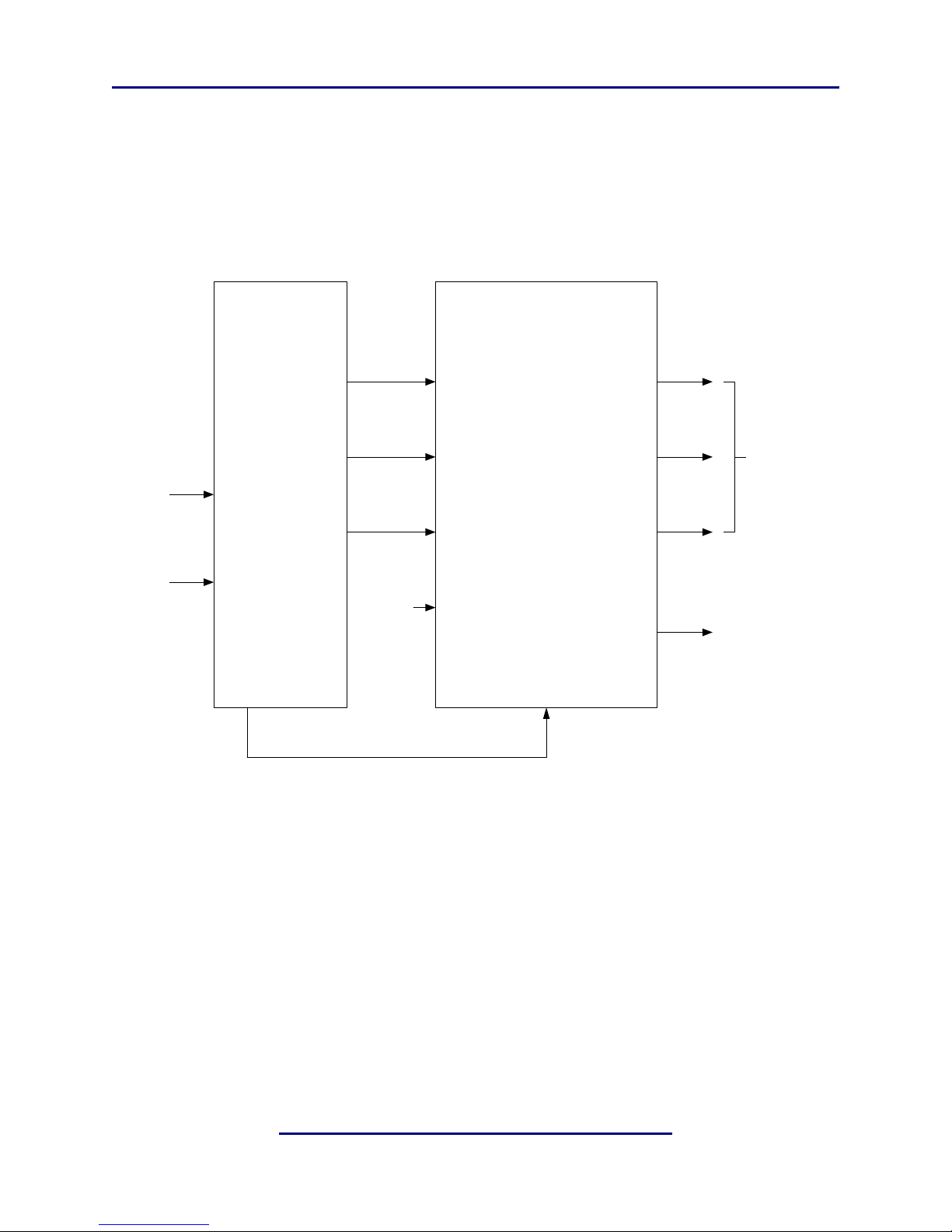
A similar situation can arise when the Dolby E system is in use, and can actually help to
automate the process of turning the upmixing process on and off with no user intervention. The metadata output of a Dolby E decoder (DP572 or other) provides information
that can be used by the UPMAX to control upmixing. Connecting a pin-to-pin cable between the metadata connectors on the two units, upmixing can automatically be turned on
and off, and audio will be smoothly crossfaded between the two modes. Figure 3-2 shows
how this can be easily accomplished.
Figure 3-2 UPMAX with Dolby DP572 Dolby E Decoder
The result is a clean, consistent 5.1 channel program that is discrete when Dolby E is present and is upmixed when PCM is present, but with no audible change apparent to listeners
or viewers.
15
Page 22

Linear Acoustic UPMAX User Guide Applications
3.2 Factory Presets
To get users up and running as quickly as possible, a few basic presets have been created
for different situations. The name of the game with this unit is “play”. There is no possible
way that presets appropriate for every situation could be generated, so we have included a
few to get you started. By all means, make adjustments, listen, store your new preset with
a name of your choice when you get it just right.
The UPMAX ships with the following factory presets:
• Music Full - Straight two-channel to 5.1 channel upmixing, with the center channel
spread across the Left front, Center, and Right front outputs. This is very useful for
programming that either contains dialogue with music or is just mono dialogue as it
nicely fills the front three channels, and feeds the surrounds when appropriate.
• MUSIC Narrow - Straight two-channel to 5.1 channel upmixing, but with the Center
channel kept fully discrete with no spread into Left front and Right front channels.
Useful for film mixes and certain music mixes. Two-channel mono programs will be
reproduced from the Center channel only. Note that Sum to LFE is enabled by default.
• COMMERCIAL DEEP - Straight two-channel to 5.1 channel upmix with the Surround audio positioned all the way to the back and the Center channel spread by the
standard 33%.
• Quad - Two-channel to 4.1 channel upmixing, with audio coming from Left front,
Right front, Left surround, Right surround and LFE channels and nothing from the
Center channel. This preset is useful for creating a surround “bed” with a hole in the
center into which a wet or ambient announce feed can be added. Innovated by Linear
Acoustic in 2004, this mode and Quad Spill have found widespread use in sports production including the Olympics.
• Quad Spill - Two channel quad upmixing, but with 33% “spilled” back into the Center
channel. Since there is some Center information still present, this preset is useful for
creating a 5.1 channel mix with a dry announce feed (little or no ambient information
such as audio from a voiceover booth).
• Bypass - Center Spread set to 100% and Surround Depth set to 0% resulting in two
channels in, two channels out. Useful for “soft bypass” comparisons, although using
the Up arrow from the main screen accomplishes the same thing.
16
Page 23

Linear Acoustic UPMAX User Guide
Chapter 4: Detailed Operation
This chapter discusses in detail the structure of the Linear Acoustic UPMAX, how to use
the front panel interface to access the menus, accessing and saving factory and user processing presets, and GPI and Metadata setup.
4.1 Menu Navigation
Most of it is rather obvious, and a bit of experimentation will quickly make you comfortable navigating through the submenus. If in doubt, use the Left Arrow to back out towards
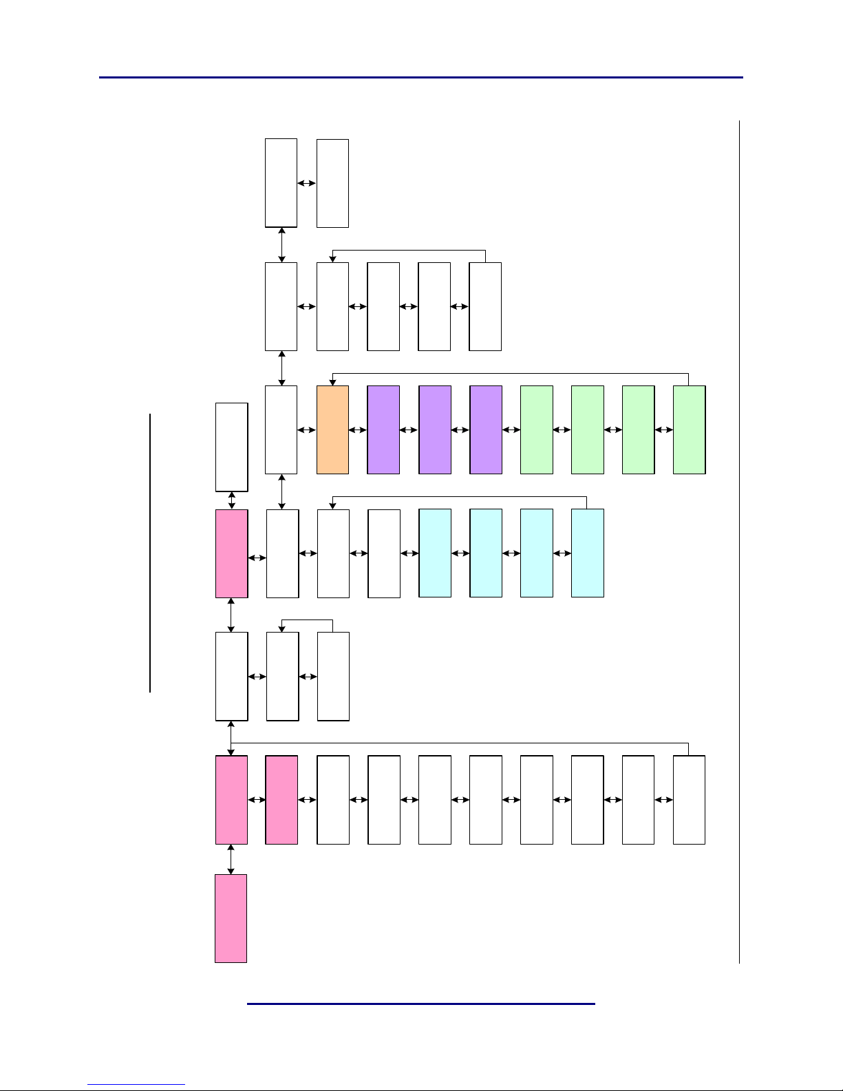
the Main menu. The menus and submenus are structured to access more complex functionality as you go deeper into the hierarchy. See the last page of this section for a detailed
menu tree.
4.1.1 Output and Upmix Status
This is the top level menu screen and it shows the output activity of the unit and the status
of the upmixing process (for local control it will show UM=y or UM=n (lower-case), and
for GPI or metadata it will show UM=Y or UM=N (upper-case). Audio channels are displayed in the order in which they appear on the physical outputs of the unit.
Sub-menus of the top menu can be accessed by pressing the Down arrow key:
• MD In PCF PGM 1-8: Metadata In Program Config as extracted from applied metadata, plus the audio coding mode (acmod) and dialnorm value from the selected program will be displayed (if that program is present in the metadata stream)
4.1.2 Statistics
Pressing the Down arrow key, the firmware revision and any installed firmware options are
displayed.
4.1.3 UPMAX Setup
This menu is the main entrance to all setup parameters for the unit, which are accessed via
the submenus described below:
• Presets Down To View: Press the Down arrow to view and modify presets- the default is the currently active preset.
• Active Preset: Preset_1 - Preset_16, or a named preset. Displays and recalls a preset
to be used by the UPMAX.
• View/Edit Preset: Select the preset to be adjusted in the following menus.
17
Page 24

Linear Acoustic UPMAX User Guide Detailed Operation
• Center Width: Controls how much of center channel output of the upmixer is spread
back into the Left and Right channel Main Outputs of the unit.!00% width equals all
Center channel information summed back into the Left and Right outputs, while 0%
equals all Center channel information sent to the Center Channel output; Default is
33%
• LCR Sum to LFE: Enable or disable the Low Frequency Effects (subwoofer) output
of the unit.
• LCR Sum Level: Controls how much of a 80Hz low pass filtered sum of the Left,
Center, and Right outputs of the upmixer is fed to the LFE channel Main Output; Default 25%
• Surround Depth: Controls back-to-front panning of the Surround output of the upmixer, where 100% equals full signal from the Left Surround and Right Surround Main
Outputs and 0% equals surround fully mixed back into the LCR outputs; Default:
100%.
4.1.4 I/O Menu
Provides for general input and output configuration via the following menus:
• Master Bypass: Activates the hard relay bypass of each AES input signal to the BNC
connector directly below it. Note that this is a “crash” switch and will likely produce
disturbances to downstream equipment. It will activate automatically in case of unit
failure and manual control is included to aid in troubleshooting.
• Clock Source: Selects the output reference source for the unit. Selections include AES
1 (default), AES 4, SDI and Internal 48kHz.
NOTE: All inputs pass through audio frame synchronization (SRCs) whose output is determined by the clock
setting. Inputs of many different sample rates can be accommodated, but reference must be from a 48kHz
source. Good clocking practices are strongly encouraged!
• Upmix On When: Controls how upmixing is engaged. Selections include:
• Set On Now (Local Control)
• GPI 1 is On - Pull GPI 1 low to turn on upmixing
• GPI 1 is Off - Pull GPI 1 low to turn off upmixing
• MD = 2/0 - If applied metadata = 2/0
• G1 or MD=2/0 - If GPI 1 is activate or metadata = 2/0
18
Page 25

Linear Acoustic UPMAX User Guide Detailed Operation
• Set off now (Local Control)
• MD = 2/0 Pgm Sel: Allows selection of any program present in an applied metadata
signal to control upmixing. This control is based on the acmod parameter of the selected program. Default is Pgm 1.
• Downmix LfRf Src (AES Input 1/AES Input 4): Selects the Left Front/Right
Front (LfRf) inputs for the downmixing encoder. To use the Upmixer and Downmixer
separately, set this to AES Input 4 and apply the LfRf signal for the downmixer to this
input. To use the LtRt or LoRo signal applied to the first AES pair (i.e. the input of the
upmixer) set this to AES Input 1.
• Upmix Src (AES Input 1 or AES Input 4): Allows the input to the upmixer to be
switched between AES 1 or AES 4. This function can also be controlled via a hot key
in the volume menu. While in the Volume menu, press Down to toggle between AES
1 and AES 4.
• When Upmixing (Mute AES In 2&3/Do Not Mute): Because AES Input 2 (C/
LFE) and 3 (LsRs) are also inputs to the Downmix encoder, it is necessary to mute
these inputs when using the upmixer and downmixer together. The upmixer will always mute these inputs, and this setting allows the same thing to happen for the downmixer. When using the downmixer for a separate program not related to the audio
applied to the upmixer (along with Downmix LfRf Src = AES Input 4), set this to Do
Not Mute.
• Downmix Type (LoRo/LtRt): Set for LoRo ITU style stereo downmix or LtRt sur-
round downmix compatible with Dolby Pro Logic and PL-II. Note that the LtRt setting introduces an additional 5msec of delay on the 7/8 output due to additional
filtering requirements of this mode.
4.1.5 Communication
Setup of TCP/IP parameters can be performed in this menu group
4.1.6 System
Selective reset to factory defaults can be performed in this menu group.
19
Page 26

Linear Acoustic UPMAX User Guide Detailed Operation
Page is very nearly blank (but good for notes)
20
Page 27
Linear Acoustic UPMAX User Guide Detailed Operation
Linear Acoustic
UPMAX V00.00.53
Input .. .. .. .. .. .. .. ..
L R C S Ls Rs L R
UPMAX Setup
Down To View
Presets
Down To View
Active Preset
Preset_1
View/Edit Preset
Preset_1
Linear Acoustic UPMA X M enu Tree
(S/W Version 0.0.98 and higher)
Statistics
Down To View
MD In PCF = 5.1+ 2
Pgm 1 2/0 DN=2 3
MD In PCF = 5.1+ 2
Pgm 2 2/0 DN=2 3
MD In PCF = 5.1+ 2
Pgm 3 2/0 DN=2 3
MD In PCF = 5.1+ 2
Pgm 4 2/0 DN=2 3
MD In PCF = 5.1+ 2
Pgm 5 2/0 DN=2 3
MD In PCF = 5.1+ 2
Pgm 6 2/0 DN=2 3
MD In PCF = 5.1+ 2
Pgm 7 2/0 DN=2 3
MD In PCF = 5.1+ 2
Pgm 8 2/0 DN=2 3
Firm w a re Version
5190 0007
De v ic e Option s
None
Center Width
33%
LCR Sum to LFE
Enable
LCR Sum Level
25%
Surro und Depth
100%
I/O
Down To View
**Master Bypass**
Disable
Clock Source
AES Input 1
When Upmixing
Mu te A ES In 2&3
Upmix On When
G1 On or MD = 2/0
MD = 2/0 Pgm S el
Pgm1
Communication
Down To View
System
Down To View
IP A ddress
192.168.0.20
Net Mask
255.255.255.255
Port
5190
MAC
0050:C2:51:21:00
Se t T o Defaults
IP Comm (All)
Downmix LfRf Src
AE S Input 4 (1)
Downmix Type
LoRo/LtRt
Upmix Src
AE S Input 1 (4)
Output .. .. .. .. .. .. .. ..
Upmx:Y L R C S Ls Rs Lo Ro
In .. .. .. .. .. .. .. ..
Out .. .. .. .. .. .. LtRt .. ..
21
Page 28

Linear Acoustic UPMAX User Guide Detailed Operation
22
Page 29

Linear Acoustic UPMAX User Guide
Chapter 5: Troubleshooting
The Linear Acoustic UPMAX is a very stable and reliable unit, and most problems can be
traced back to mis-wiring causing incorrect signals to be applied to the unit, or more than
likely mis-configuration. In an effort to speed troubleshooting, some common problems
and solutions are described below.
5.1 Problems and Possible Causes
One of the best troubleshooting features of the UPMAX is the hard-bypass of the audio
signals. This is useful because it allows instant removal of the unit from the signal path.
Hard-bypass can be accomplished two ways, the simplest being to remove AC power from
the unit by turning the power switch off. A less dramatic way to accomplish the same result
is to access the System Options menu and enable Master Bypass. If you are unsure of what
is happening in a particular system, simplifying the signal path is a good start and will help
isolate problems quickly.
5.1.1 Unit won’t power on
Check to make sure that the unit is connected to a live outlet (it happens...). If proper AC
voltage is being applied to the unit, remove power and check the fuse (the IEC inlet module has a fuse compartment that can be carefully opened with a small screwdriver). If the
fuse is blown there is a spare in the holder. Install the replacement fuse, re-insert the fuse
carrier, and re-apply power.
NOTE: Replace fuses only with the same size and rating: 5mmx20mm T1AL (250V)
5.1.2 Output Audio Clicks and Pops
This could indicate that the AES Reference is missing or at the wrong sample rate (the unit
expects to be locked to 48kHz). The unit is designed to default to an internal 48kHz reference in case the external reference is removed. This allows audio to continue, but due to
the sample rate converters present on each input pair, the outputs will be asynchronous
with the inputs. The solution is to make sure that the reference is connected.
It could also mean that audio applied to the unit is not properly referenced, or that the
equipment that the unit is feeding is not properly referenced. Using the master bypass
function of the unit is a helpful way to troubleshoot this issue.
23
Page 30

Linear Acoustic UPMAX User Guide Troubleshooting
5.1.3 Unit is Not Upmixing
From the main output screen, make sure that UM=Y (Upmix=Yes) is shown. If not, access the I/O menu, then “Upmix When” and set appropriately. Consult the Menu Tree in
Chapter 4 or the Quick Start Guide for more information.
If UM=Y, make sure that the unit is not in Master Bypass (relay bypass) under the I/O
menu.
Lastly, ensure that Center Width is between 0% and 33% and Surround Depth is 100%.
Adjusting these controls can set the surroundfield back to stereo. If Center Width is set to
100% (Center from Lf/Rf) and Surround Depth is set to 0% (Surround from LfRf), the
output signal will be stereo! Normally, these adjustments are Center = 0% and Surround
= 100%.
5.1.4 Cannot Manually Control Upmixing
If on the main screen UM=N or UM=Y (all caps), then the unit is set to respond to GPI
or metadata commands. Access the I/O menu and set the unit back to either of the manual
modes (Upmix On Now or Upmix Off Now).
24
Page 31
Linear Acoustic UPMAX User Guide
Chapter 6: Specifications
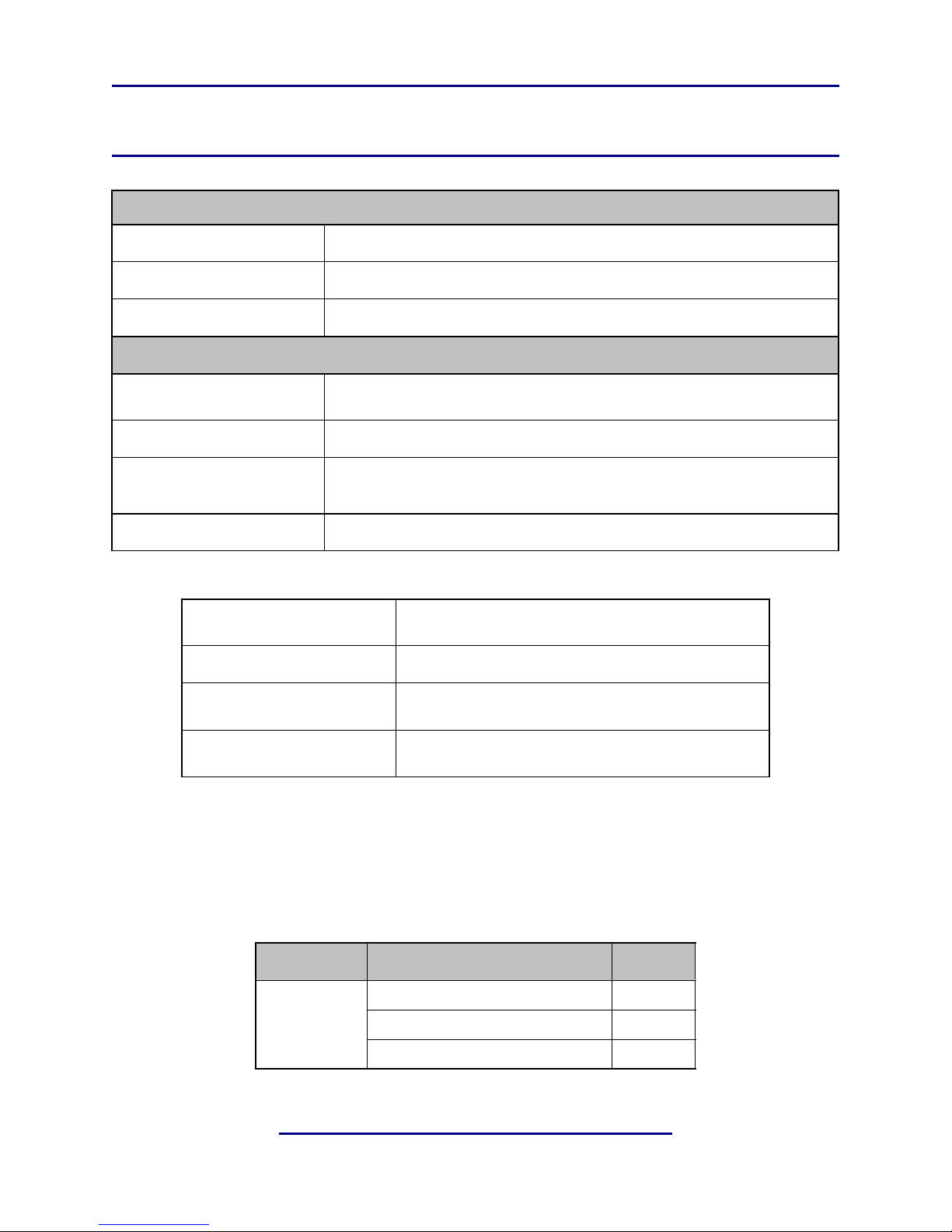
Figure 6-1 Electrical
Processing
Algorithm
Sampling Rate
Word Length
Digital I/O
Digital Audio I/O
Reference
HD/SD-SDI
Auto-Sensing I/O
Ethernet
Dimensions
Net Weight
UPMAX®: 5.1-channel upmixing, automatic bypass of discrete content
48kHz
24-bits
All inputs and outputs via BNC female connectors, unbalanced, 75-, with internal termi-
nation for the inputs. Signal levels per SMPTE 276M/ AES-3ID-2001
48 kHz via AES DARS reference or SDI input
De-embed up to 16 audio channels from SDI, process and/or encode, and re-embed up to 16
channels; Signal levels per SMPTE 292M /259M; Supports up to 1080i/60/59.94/50 Hz
100 to 1000 BASE-T via RJ-45 connector
Table 6-1 Physical
1RU
H = 1.75 in (45 mm) W = 19 in (483 mm) D = 13.25 in (337 mm)
12.5 lb (6 kg) approximate
Environmental
Power Requirements
Operating: 0 – 50ºC
Non-operating: -20 – 70ºC
Dual redundant auto-sensing power supplies, each rated at
100–240 VAC, 50–60 Hz, 40W maximum
Latency
The UPMAX has very low latency which is fixed for the main path. Downmix latency depends on the
type chosen but is also fixed.
Table 6-2 Fixed latency for different modes and functions
Mode Function Latency
Main Output 5 msec
Any
LoRo Downmix 6 msec
LtRt Downmix 11 msec
25
Page 32

Linear Acoustic UPMAX User Guide Specifications
Connector Pinouts
Table 6-3 Metadata Input Port Pinout
Pin Connection
1Shield
2 TX A asynchronous data out –
3 RX B asynchronous data in +
4Ground
5NC
6Ground
7 TX B asynchronous data out +
8 RX A asynchronous data in –
9Shield
F-DB9 connector with full-duplex RS-485 protocol running at 115 kbps. Pinout is compatible with
SMPTE 207M. Pin-for-pin compatible with Dolby Metadata (SMPTE RDD6).
Regulatory
North America: Designed to comply with the limits for a class A digital device pursuant to Part 15 of
the FCC rules (CFR). Designed for U.S. and Canadian listing with UL.
Europe: Designed to comply with the requirements of Low Voltage Directive 73/23/EEC and EMC
Directive 89/336/EEC. Designed for RoHS and WEEE compliance.
26
Page 33

Linear Acoustic UPMAX User Guide Specifications
27
Page 34

Linear Acoustic UPMAX User Guide Specifications
28
Page 35

Linear Acoustic UPMAX User Guide Specifications
29
Page 36

 Loading...