

Page 1
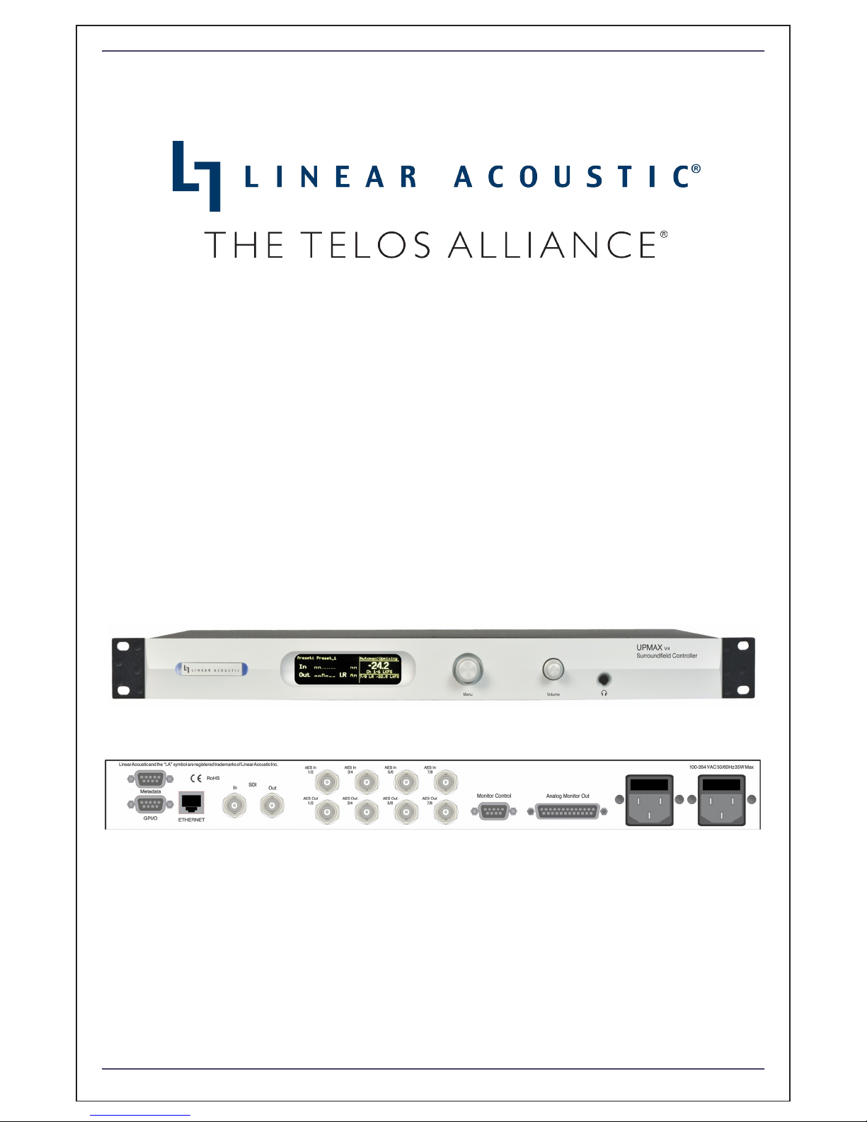
UPMAX v4 Surroundfield Controller
User Guide
Release Date: January 2019
Software Version: 0.0.20 and later
Linear Acoustic Inc.
Phone: 717-735-3611
FAX: 717-735-3612
Web:
TelosAlliance.com/Linear
Page 2

Warranty Information
For the latest Telos Alliance warranty, visit: telosalliance.com/warranty
Page 3

Regulatory Notices and Fusing Information
e
k
t
h
FCC
This equipment has been tested and found to comply with the limits for a Class A digital device,
pursuant to Part 15 of the FCC Rules. These limits are designed to provide reasonable protection
against harmful interference when the equipment is operated in a commercial environment. This
equipment generates, uses, and can radiate radio frequency energy and, if not installed and used in
accordance with this instruction manual, may cause harmful interference to radio communications.
Operation of this equipment in a residential area is likely to cause harmful interference in which cas
the user will be required to correct the interference at his or her own expense.
Canada
This Class A digital apparatus complies with Canadian ICES-003.
UL
WARNING: Troubleshooting must be performed by a trained technician. Do not
attempt to service this equipment unless you are qualified to do so.
Check that the correct fuses have been installed. To reduce the risk of fire, replace
only with fuses of the same type and rating.
Exposed portions of the power supply assembly are electrically “hot”. In order to reduce the ris
of electrical shock, the power cord MUST be disconnected when the power supply assembly is
removed.
The ground terminal of the power plug is connected
directly to the chassis of the unit. For continued protection
against electric shock, a correctly wired and grounded
(earthed) three-pin power outlet must be used. Do not use
a ground-lifting adapter and never cut the ground pin on
the three-prong plug.
UK
As the colours of the cores in the mains lead may not correspond with the coloured markings
identifying the terminals in your plug, proceed as follows:
x The core that is coloured green and yellow must be connected to the terminal in the
plug identified by the letter E or by the earth symbol
and yellow.
x The core that is coloured blue must be connected to the terminal that is marked with
letter N or coloured black.
x The core that is coloured brown must be connected to the terminal that is marked wit
the letter L or coloured red.
x This apparatus must be earthed.
or coloured green or green
Page 4

s equipment complies with the EMC requirements of EN55103-1 and EN55103-2 when operated in an E2 environment
e
ccordance with this manual.
unit complies with the safety standard EN60065. The unit shall not be exposed to dripping or splashing and no objects filled with liquids, such as
e cups, shall be placed on the equipment. To ensure safe operation and to guard against potential shock hazard or risk of fire, the following must be
rved:
Ensure that your mains supply is in the correct range for the input power requirement of the unit.
Ensure fuses fitted are the correct rating and type as marked on the unit.
The unit must be earthed by connecting to a correctly wired and earthed power outlet.
The power cord supplied with this unit must be wired as follows:
ateriel est conforme à la norme EN60065. Ne pas exposer cet appareil aux éclaboussures ou aux gouttes de liquide. Ne pas poser d'objets remplis de
de, tels que des tasses de café, sur l'appareil. Pour vous assurer d'un fonctionnement sans danger et de prévenir
choc électrique ou tout risque d'incendie, veillez à observer les recommandations suivantes.
Le selecteur de tension doit être placé sur la valeur correspondante à votre alimentation réseau.
Les fusibles doivent correspondre à la valeur indiquée sur le materiel.
Le materiel doit être correctement relié à la terre.
Le cordon secteur livré avec le materiel doit être cablé de la manière suivante:
es Gerät entspricht der Sicherheitsnorm EN60065. Das Gerät darf nicht mit Flüssigkeiten (Spritzwasser usw.) in Berührung kommen; stellen Sie
Gefäße, z.B. Kaffeetassen, auf das Gerät. Für das sichere Funktionieren des Gerätes und zur Unfallverhütung (elektrischer Schlag, Feuer) sind die
nden Regeln unbedingt einzuhalten:
Der Spannungswähler muß auf Ihre Netzspannung eingestellt sein.
Die Sicherungen müssen in Typ und Stromwert mit den Angaben auf dem Gerät übereinstimmen.
Die Erdung des Gerätes muß über eine geerdete Steckdose gewährleistet sein.
Das mitgelieferte Netzkabel muß wie folgt verdrahtet werden:
ta apparecchiatura è stata costruita in accordo alle norme di sicurezza EN60065. Il prodotto non deve essere sottoposto a schizzi, spruzzi e
iolamenti, e nessun tipo di oggetto riempito con liquidi, come ad esempio tazze di caffè, deve essere appoggiato sul dispositivo. Per una perfetta
ezza ed al fine di evitare eventuali rischi di scossa êlettrica o d'incendio vanno osservate le seguenti misure di sicurezza:
Assicurarsi che il selettore di cambio tensione sia posizionato sul valore corretto.
Assicurarsi che la portata ed il tipo di fusibili siano quelli prescritti dalla casa costruttrice.
L'apparecchiatura deve avere un collegamento di messa a terra ben eseguito; anche la connessione rete deve
avere un collegamento a terra.
Il cavo di alimentazione a corredo dell'apparecchiatura deve essere collegato come segue:
unidad cumple con la norma de seguridad EN60065. La unidad no debe ser expuesta a goteos o salpicaduras y no deben colocarse sobre el equipo
ientes con liquidos, como tazas de cafe. Para asegurarse un funcionamiento seguro y prevenir cualquier posible peligro de descarga o riesgo de
dio, se han de observar las siguientes precauciones:
Asegúrese que el selector de tensión esté ajustado a la tensión correcta para su alimentación.
Asegúrese que los fusibles colocados son del tipo y valor correctos, tal como se marca en la unidad.
La unidad debe ser puesta a tierra, conectándola a un conector de red correctamente cableado y puesto a tierra.
El cable de red suministrado con esta unidad, debe ser cableado como sigue:
a enhet uppfyller säkerhetsstandard EN60065. Enheten får ej utsättas för yttre åverkan samt föremål innehållande vätska, såsom kaffemuggar, får ej
ras på utrustningen." För att garantera säkerheten och gardera mot eventuell elchock eller brandrisk, måste följande observeras:
Kontrollera att spänningsväljaren är inställd på korrekt nätspänning.
Konrollera att säkringarna är av rätt typ och för rätt strömstyrka så som anvisningarna på enheten föreskriver.
Enheten måste vara jordad genom anslutning till ett korrekt kopplat och jordat el-uttag.
El-sladden som medföljer denna enhet måste kopplas enligt foljande:
unit voldoet aan de EN60065 veiligheids-standaards. Dit apparaat mag niet worden blootgesteld aan vocht. Vanwege het risico dat er druppels in
pparaat vallen, dient u er geen vloeistoffen in bekers op te plaatsen. Voor een veilig gebruik en om het gevaar van electrische schokken en het risico
rand te vermijden, dienen de volgende regels in acht te worden genomen:
Controleer of de spanningscaroussel op het juiste Voltage staat.
Gebruik alleen zekeringen van de aangegeven typen en waarden.
Aansluiting van de unit alleen aan een geaarde wandcontactdoos.
De netkabel die met de unit wordt geleverd, moet als volgt worden aangesloten:
Live—Brown Neutral—Blue Earth—Green/Yellow
Phase—braun Nulleiter—blau Erde—grün/gelb
Filo tensione—Marrone Neutro—Blu Massa—Verde/Giallo
Vivo—Marrón Neutro—Azul Tierra—Verde/Amarillo
IMPORTANT SAFETY NOTICE
GB
IMPORTANT – NOTE DE SECURITE
F
Phase—Brun Neutre—Bleu Terre—Vert/Jaune
WICHTIGER SICHERHEITSHINWEIS
D
NORME DI SICUREZZA – IMPORTANTE
I
AVISO IMPORTANTE DE SEGURIDAD
E
VIKTIGA SÄKERHETSÅTGÄRDER!
S
Fas—Brun Neutral—Blå Jord—Grön/Gul
BELANGRIJK VEILIGHEIDS-VOORSCHRIFT:
NL
Fase—Bruin Nul—Blauw Aarde—Groen/Geel
Page 5
Fusing Information
p
p
WARNING: To reduce the risk of fire, replace fuses only with the same type
and rating.
Both units use a universal switching power supply that handles the full range of
nominal mains voltages between 90 and 264 VAC and any frequency between 50 Hz
and 60 Hz.
Check Main Fuse
The Main fuse rating is:
T 1A L (1 Amp, 250 V, 20 mm, time-lag, low breaking capacity) for all operating
voltages.
WARNING: The power to the unit must be off when the following steps are
erformed. Ensure that the main power cable to the unit is not connected to a
ower source.
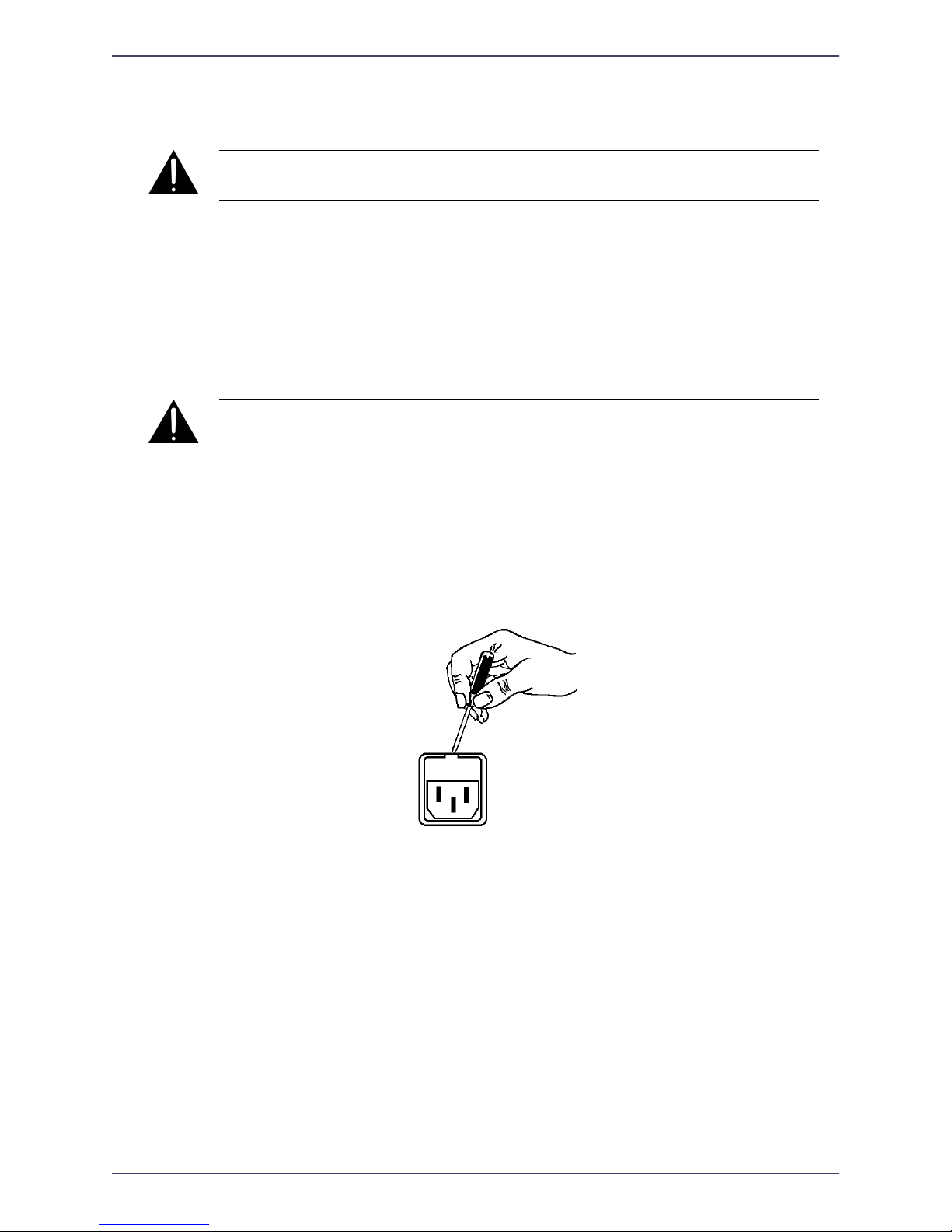
1. Open the fuse compartment door in the AC power input housing with a small flatblade screwdriver (Figure 1). Carefully pull out the fuse carrier.
2. Check that the replacement fuse has the correct rating. The fuse carrier must be
inserted into the compartment carefully. Do not force the carrier into the
compartment or both could be damaged.
3. Snap the fuse compartment door closed.
Internal Fuse
The switching power supply contains a separate fuse. Most fault conditions should be
protected by the main fuse.
If you find it necessary to replace the internal fuse, be certain to replace it with a fuse
of the same type and rating as printed on the switching power supply board.
Figure 1 Checking the Main Fuse
Page 6

Page 7

Linear Acoustic AERO.100 User Guide
Table of Contents
List of Figures .........................................................................................................................................xi
Chapter 1: Introduction .................................................................................................................5
1.1 Principles of Operation..........................................................................................5
1.2
Warranty...................................................................................................................7
Chapter 2: Connections and Quick Setup.....................................................................9
2.1 Unpacking and Inspection.....................................................................................9
2.2 Installation ...............................................................................................................9
2.3 Rear Panel ..............................................................................................................10
2.3.1 Connection Ports..................................................................................10
2.4 Quick Setup Notes ...............................................................................................11
Chapter 3: Applications ..............................................................................................................13
3.1 Typical Scenarios ..................................................................................................13
3.1.1 General Notes.......................................................................................14
3.1.2 Two-Channel Interstitial Programming ............................................14
3.1.3 Sports Production ................................................................................14
3.1.4 Music Applications...............................................................................15
3.2 Factory Presets ......................................................................................................15
Chapter 4: Detailed Operation...............................................................................................17
4.1 User Interface........................................................................................................17
4.2 Menu Navigation ..................................................................................................17
4.3 Statistics..................................................................................................................17
4.4 UPMAX Setup ......................................................................................................18
4.4.1 Presets Down To View .......................................................................18
4.4.2 User Preset ............................................................................................18
vii
Page 8

Linear Acoustic AERO.100 User Guide
4.4.3 Preset Params........................................................................................18
4.5 I/O Menu ..............................................................................................................19
4.5.1 Master Bypass .......................................................................................19
4.5.2 GPI Control Enable.............................................................................19
4.5.3 GPI Function (1 - 4) ............................................................................19
4.5.4 GPI Preset (1 - 4) .................................................................................20
4.5.5 Monitor Mode.......................................................................................20
4.5.6 Upmix LfRf When ...............................................................................20
4.5.7 When Upmixing, (Mute Ch 3 - 6 / Do Not Mute).........................20
4.5.8 Downmix Type.....................................................................................20
4.5.9 Downmix --> 7/8 ................................................................................20
4.5.10 Downmix Center Level .......................................................................20
4.5.11 Downmix Surround Level ..................................................................20
4.5.12 Downmix LFE Level...........................................................................21
4.5.13 7/8 in Channel Mode ..........................................................................21
4.5.14 SRC Bypass............................................................................................21
4.5.15 Headphone Boost ................................................................................21
4.5.16 Clock Source Type ...............................................................................21
4.5.17 Clock Source .........................................................................................21
4.5.18 Audio Input Sources (Channels 1-8).................................................21
4.5.19 SDI Embed ...........................................................................................22
4.5.20 SDI Out Destination (Channels 1-16) ..............................................22
4.5.21 Metadata Setup .....................................................................................22
4.5.22 Loudness Measurement.......................................................................23
4.5.23 GPO Alert When (1-4)........................................................................23
4.5.24 GPO Threshold (1-4) ..........................................................................23
4.5.25 GPO On Delay (1-4) ...........................................................................23
4.5.26 GPO Off Delay (1-4)...........................................................................23
4.6 Test Tone Control ................................................................................................23
4.6.1 Test Tone...............................................................................................23
4.6.2 Test Tone Type.....................................................................................24
viii
Page 9

Linear Acoustic AERO.100 User Guide
4.6.3 Test Tone Frequency ...........................................................................24
4.6.4 Test Amplitude .....................................................................................24
4.7 Analog Control......................................................................................................24
4.8 Communication.....................................................................................................24
4.9 System.....................................................................................................................24
4.10 Monitor Calibration (Analog Outputs)..............................................................24
4.10.1 Main Channel SPL Adjustment..........................................................25
4.10.2 Subwoofer SPL Adjustment ...............................................................26
Chapter 5: Troubleshooting ....................................................................................................27
5.1 Problems and Possible Causes............................................................................27
5.1.1 Unit won’t power on............................................................................27
5.1.2 Output Audio Clicks and Pops ..........................................................27
5.1.3 Unit is Not Upmixing ..........................................................................28
5.1.4 Cannot Manually Control Upmixing.................................................28
5.1.5 Analog Outputs Have Noise ..............................................................28
Chapter 6: Specifications ..........................................................................................................29
ix
Page 10

Linear Acoustic AERO.100 User Guide
x
Page 11

Linear Acoustic UPMAX v4 User Guide
List of Figures
1-1 Audio Block Diagram .........................................................................................................................6
2-1 Rear Panel ...........................................................................................................................................10
6-1 Electrical .............................................................................................................................................29
xi
Page 12

Linear Acoustic UPMAX v4 User Guide
xii
Page 13

Linear Acoustic UPMAX v4 User Guide Introduction
Chapter 1: Introduction
The Linear Acoustic UPMAX v4 produces a 5.1 channel audio signal that is perfect for
eventual transmission to all consumers. The unit accepts a 2-channel input and “upmixes”
it to fill as many of the 5.1 output channels as the user selects. Any input signal from mono
to stereo to LtRt (Left Total/Right Total) surround encoded audio and even three channel
(M&E plus Dialog) can be applied to the Main Inputs and an output will be produced that
maintains consistency with other 5.1 channel programming.
The UPMAX v4 provides the following features:
• Advanced upmixing algorithm for stable, convincing surround experience.
• Fully downmix compatible
• Upmixed surroundfield is infinitely adjustable
• External inputs allow crossfaded bypassing of upmixing to enable discrete 5.1 channel
audio to pass untouched, or mixing of external and upmixed content
• Built-in independent LoRo/LtRt encoder
• Relay bypassed I/O for “mission critical” broadcast applications.
• HD/SD-SDI I/O for audio and metadata
1.1 Principles of Operation
The UPMAX v4 contains two paths for audio signals. The first path contains an upmixer,
a bass extension filter to create the LFE (Low Frequency Effects) or subwoofer channel,
and a simple but powerful set of mix controls to vary each element of the surroundfield.
The second path provides discrete inputs for the Center, LFE, Ls (Left Surround), Rs
(Right Surround), Lf (Left Front) and Rf (Right Front) channels. The upmixed and discrete
outputs can be crossfaded between to allow smooth transitions between upmixed and discrete audio.
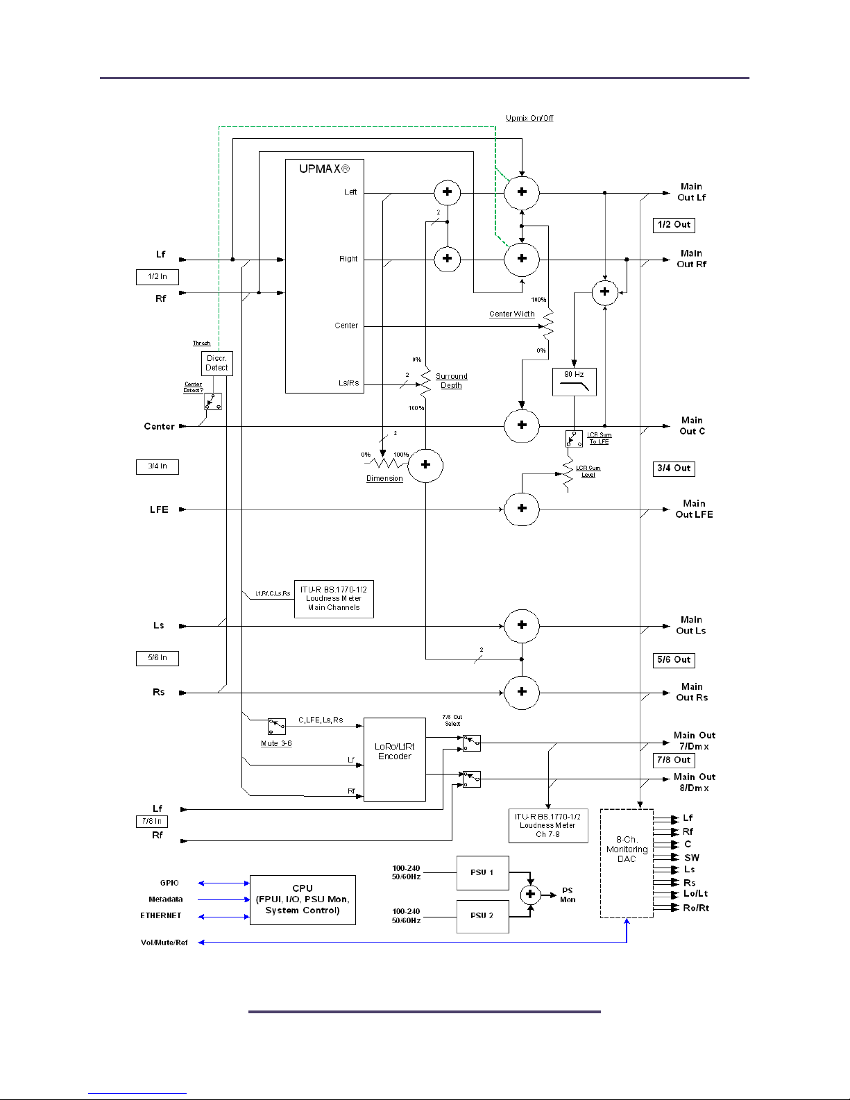
Please refer to Figure 1-1. It should be noted that this diagram is a general representation
of signal flow. Please consult the appropriate section of this manual for an accurate description of actual functionality.
5
Page 14
Linear Acoustic UPMAX v4 User Guide Introduction
Figure 1-1 Audio Block Diagram
6
Page 15

Linear Acoustic UPMAX v4 User Guide Introduction
1.2 Warranty
For the latest Telos Alliance warranty, visit: telosalliance.com/warranty
7
Page 16

Linear Acoustic UPMAX v4 User Guide Connections and Quick Setup
Chapter 2: Connections and Quick Setup
This chapter covers all required connections for the UPMAX v4.
2.1 Unpacking and Inspection
Before unpacking the unit, inspect the outer carton for shipping damage. If the carton
shows damage, inspect the unit in those areas. Please save the carefully designed shipping
carton and packing materials. In the unlikely event that the unit needs to be returned to the
factory, alternate cartons or packing materials may not be adequate and can cause damage
not covered by warranty.
The following essential items are provided with the unit:
• Bag containing:
• Quick-start sheet to get you up and running
• Two IEC power cords (style matches country of order);
• USB stick with this manual
• Spare fuses and a handy black pen.
• Warranty information: Please fill out and return the warranty card to Linear Acoustic
to ensure your software and documentation are kept up to date.
2.2 Installation
UPMAX v4 installation requires:
• One standard rack space unit with ADEQUATE VENTILATION (the unit relies on
convection cooling from side-panel vents);
• standard 75-Ohm BNC cables for digital signal connections;
To connect to digital equipment with 110-Ohm XLR connectors, use impedancematching transformers (available from Canare, Neutrik and other manufacturers).
• Proper reference. The unit will default to internal 48kHz with no signals applied, but
AES 1/2 or SDI can be used as the reference. For proper plant timing, proper reference selection in imperative. Note that if SDI embedding is active, clock source will
automatically be forced to SDI.
9
Page 17
Linear Acoustic UPMAX v4 User Guide Connections and Quick Setup
2.3 Rear Panel
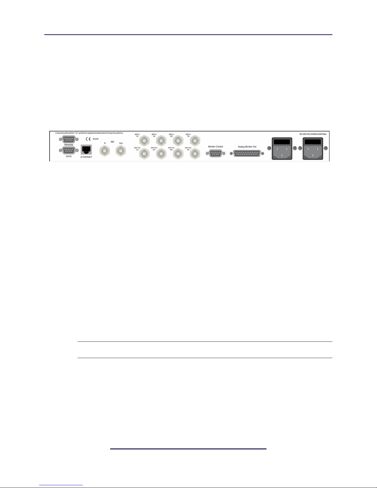
The rear panel of the UPMAX v4 contains its electrical I/O.
2.3.1 Connection Ports
All of the UPMAX v4’s connections are on the rear panel and are described in detail below.
See Chapter 5: Specifications for specific pinouts.
Figure 2-1 Rear Panel
• Metadata I/O: RS-485 connection accepts the metadata output of any SMPTE
RDD6 (i.e. Dolby) compliant metadata source. Can be used to control upmixing and
recall of presets.
• SDI Input/SDI Output: Allows access to all 16 audio channels for embedding and
de-embedding. VANC metadata per SMPTE 2020 can also be extracted.
• GPI/O: Connect dry contact closures here to control upmixing on/off. Note that
GPI functions require held closures for the duration of the desired function. Status of
GPI will be reflected on the corresponding GPO pin.
• ETHERNET: Used for software upgrades and SNMP monitoring.
• Main Audio Input: Connect the 48kHz PCM signals to these inputs. The input channels are arranged as follows: 1/2 = Left front/Right front, 3/4 = Center/LFE, 5/6 =
Left surround/Right surround, and 7/8 = Stereo Aux input.
NOTE: Appropriate reference should be applied AND selected for proper operation.
• Main Audio Outputs: Main 48kHz processed digital audio outputs. 1/2 = Left
Front/Right Front, 3/4 = Center/LFE, 5/6 = Left Surround/Right Surround.
• 7/8 (LoRo/LtRt) Output: A two channel downmixed version of the audio applied
to Inputs 1-6, or a time-aligned passthrough of the 7/8 input.
• Monitor Control: Remote control of analog volume, mute, and return to reference using a standard rotary encoder, switches, and LEDs (with series resistors). A suitable
high-quality remote control is available from Linear Acoustic.
10
Page 18

Linear Acoustic UPMAX v4 User Guide Connections and Quick Setup
• Analog Monitor Outputs: A +4dBu balanced analog version of outputs 1-8. Volume
can be controlled from the front panel joystick encoder or via the Remote port.
2.4 Quick Setup Notes
The Linear Acoustic UPMAX v4 is configured at the factory and is ready to go on the air
after making the proper input and output connections and determining if upmixing is desired.
• Apply a two-channel (stereo or LtRt) signal to Main Input 1/2
• The main menu will default to showing output meters, and you should see activity on
some or all of the first six meters.
• Upmixed audio will be output from the Main Out 1-6 AES outputs in the following
format: 1/2 = Left Front/Right Front, 3/4 = Center/LFE, 5/6 = Left Surround/
Right Surround
• You will also have audio on the analog outputs in the same format as above.
The best way to learn the processor is to explore the different settings with audio applied
and monitored. There are several factory presets to support many different tastes. Some
presets may not sound much different at first, but will perform very depending on program
content. When in doubt, try turning the upmixing process off or as a last resort use the
Master Bypass feature which will remove the UPMAX v4 completely from the signal path.
11
Page 19

Linear Acoustic UPMAX v4 User Guide Applications
Chapter 3: Applications
The UPMAX v4 is intended to be used either in the production or distribution stages of
5.1 channel programming, and also selectively in transmission environments. Cable and
satellite facilities may find it useful as the distribution and transmission sections are usually
very close together. For terrestrial emission (transmission) applications such as at DTV stations, the Linear Acoustic AERO series of processors may be a more appropriate choice
as they contain requisite loudness control, dynamic range processing and additional useful
features such as Dolby encoding and decoding.
The Linear Acoustic UPMAX v4 is not a substitute for a good, discrete multichannel mix
(if one is available), however it is a useful tool for creating one.
That being said, the UPMAX v4 is an excellent tool useful in either creating a 5.1 channel
version of a program when few or no other elements exist, and also for creating a solid
foundation for a true discrete multichannel mix.
This chapter discusses several applications of the UPMAX v4:
• General application notes
• Integrating 2-channel commercials into a 5.1 channel program
• Creating a 5.1 channel sports program from stereo plus natural sources
• Use for music programming
• Discussion of presets stored in the unit
3.1 Typical Scenarios
Below are some application examples to give users some guidance in real-world situations.
However, before continuing, it is absolutely imperative that a proper multichannel monitoring environment be set up and calibrated before every mix. If the mix cannot be heard
properly, then it cannot be created properly.
The Linear Acoustic
created. From hands-on adjust-as-you-go environments like a music awards program to
set-and-forget applications like helping two-channel commercials fit into 5.1-channel programming, the UPMAX v4 is the answer.
UPMAX v4 is useful almost anywhere a multichannel mix must be
13
Page 20

Linear Acoustic UPMAX v4 User Guide Applications
3.1.1 General Notes
The latency of the UPMAX v4 has been kept as low as possible. To take best advantage of
this, make sure it is installed in a synchronous system (i.e. as a send and return to a console)
and set the Sample Rate Converter Bypass to ON (i.e. SRCs are off). This will keep the
latency at around 4msec. Make sure to take care not to bring up both the send and return
audio else even this very low 4msec might cause comb filtering.
In general, an upmixer responds to level to control Left to Center to Right positioning, and
phase to control front to back positioning. UPMAX v4 operates across multiple bands to
minimize low frequency content causing center channel build-up. However, dialog can do
the same thing, especially announce dialog. It was discovered some years ago that simply
separating a mix into two parts: Main Stereo (no announce) and a separate Announce channel then upmixing only the Main Stereo and combining with a time aligned version of the
Announce audio produces a very wide and stable result free of odd sounding artifacts.
3.1.2 Two-Channel Interstitial Programming
One of the largest complaints viewers is the annoying fact that stereo commercials don’t
seem to “fit” into the 5.1-channel program. This is because in many cases, the commercials
are simply transmitted on the Left and Right channels of a 5.1-channel program. The net
result is that during the program, dialogue comes from the center speaker, but at commercial or station breaks, all of the dialogue comes from the left and right speakers. It can be
a jarring experience.
The first application is one where the UPMAX v4 processes the stereo material allowing
it to fit nicely within a 5.1 channel program. Figure 3-1 shows this scenario. Note that the
two channel material is simply input to the UPMAX v4 and a 5.1 channel signal is available
at the output. Either of the Commercial or Music presets can be chosen, and are explained in detail at the end of this chapter.
3.1.3 Sports Production
Sports production could be as simple as creating an excellent and wide stereo mix with dialog on a separate bus. Using the UPMAX v4, the stereo mix can be turned into 5.1 and
the announce audio passed around the upmixer.
A Center Detect control was added to the Auto mode to facilitate handling this type of 3channel audio. It ignores the presence of audio on channel 3 (i.e. the announce audio), time
aligning it and summing it with the upmixed version of the audio from input channels 1-2.
This mode is also useful if the audio might be of several different flavors. With Center Detect set to off, Stereo, 3-channel, and 5.1 channel input audio can be automatically handled
with no operator intervention. A tip would be to adjust the crossfade timing to be as fast
as practical.
14
Page 21

Linear Acoustic UPMAX v4 User Guide Applications
3.1.4 Music Applications
Upmixing stereo music stems is an excellent application of the UPMAX v4. In general, either of the music presets can be chosen, with the only difference being that Music Full
spreads some of the upmixed center channel audio back into Left front and Right front.
The default Center Width of 33% was determined mathematically and verified by professional audio mixers who adjusted the width until they could just tell that audio was also
coming from Left front and Right front, then backed it down a notch. Good old science
proven out by practical experience!
If you desire a music mix that uses only some of the Center channel, a common practice,
try flipping the Center Width percentage: i.e. set it for 67%. This can leave a nice spot for
lead vocals or announce if they are available as isolated outputs.
Another control that is useful to try with music is the Dimension control which determines
how much of the upmixed Left front/Right Front audio to leak into Left surround and
Right surround. This has the effect of filling in the hole that can sometimes exist between
the front and rear channels - the audible result is similar to pushing the sides out a bit. Note
that it really does not take much to produce a decent effect, around 10% is good. Too
much can become problematic during certain downmixes so use with care.
3.2 Factory Presets
To get users up and running as quickly as possible, a few basic presets have been created
for different situations. The name of the game with this unit is “play.” There is no possible
way that presets appropriate for every situation could be generated, so we have included a
few to get you started. By all means, make adjustments, listen, store your new preset with
a name of your choice when you get it just right.
The UPMAX v4 ships with the following factory presets:
• Music Full- Straight two-channel to 5.1 channel upmixing, with the Center Width at
33%. This is very useful for programming that either contains dialogue with music or
is just mono dialogue as it nicely fills the front three channels, and feeds the surrounds
when appropriate.
• Music Narrow - Straight two-channel to 5.1 channel upmixing, but with the Center
channel kept discrete. Useful for film mixes and certain music mixes.
• Music Wide - Straight two-channel to 5.1 channel upmixing, but with the Center
Width spreading audio 67% to the Left front and Right front outputs and Center
Channel Detect set to Off. It appropriately fills the front three channels, and feeds the
surrounds when appropriate. Importantly, it upmixed content lower in the Center
channel leaving a “hole” with some music, perfect for announce audio or even an isolated bus with lead vocals.
15
Page 22

Linear Acoustic UPMAX v4 User Guide Applications
• Commercial Deep - Useful for “blind” upmixing (i.e. no skilled operator present).
Conservative two-channel to 5.1 channel upmix with the Surround audio positioned
100% to the back and Center Width at the standard 33%. Dimension is set to 0% to
protect against oddly mixed content
• Sports 3 Chan - Upmixes audio present on input channels 1-2 with Center Width at
33%, time aligns and mixes audio on channel 3 with the resulting upmixed audio. Center Detect is set to Off so that 3-channel audio will not trigger automatic upmixing.
Note that any discrete LFE information applied to channel 4 will also pass.
• Sprts 3 Ch Wide- Upmixes audio present on input channels 1-2 with Center Width at
67%, and time aligns and mixes audio on channel 3 with the resulting upmixed audio.
Center Detect is set to Off so that 3-channel audio will not trigger automatic upmixing.
Note that any discrete LFE information applied to channel 4 will also pass.
16
Page 23

Linear Acoustic UPMAX v4 User Guide Detailed Operation
Chapter 4: Detailed Operation
This chapter discusses in detail the structure of the Linear Acoustic UPMAX v4, how to
use the front panel interface to access the menus, accessing and saving factory and user
processing presets, and GPI and Metadata setup.
4.1 User Interface
With the exception of headphone output volume control, all adjustments are made using
the joystick on the front panel.
Joystick Operations
• Pressing the joystick to the left acts as an escape key and backs you out towards the
main menu.
• Pressing the joystick to the right navigates through the menu or submenu categories.
It also acts as an Enter control when adjusting parameters
• Pressing the joystick up or down navigates through a particular menu or submenu category.
• Turning the joystick allows adjustment of parameters and control settings.
• Pressing the joystick in cycles through the upmix modes.
4.2 Menu Navigation
Most of it is rather obvious, and a bit of experimentation will quickly make you comfortable navigating through the submenus. If in doubt, press the joystick repeatedly to the left
to back out towards the Main menu. The menus and submenus are structured to access
more complex functionality as you go deeper into the hierarchy. See the last page of this
section for a detailed menu tree.
4.3 Statistics
Pressing the joystick down, the firmware revision, any installed firmware options, and information regarding the DSPs and application are displayed.
17
Page 24

Linear Acoustic UPMAX v4 User Guide Detailed Operation
4.4 UPMAX Setup
This menu is the main entrance to all setup parameters for the unit, which are accessed via
the submenus described below:
4.4.1 Presets Down To View
Press the Down arrow to view and modify presets- the default is the currently active preset.
4.4.2 User Preset
Six factory presets (See Chapter 3) plus user Preset_7 - Preset_16, or a named preset. Displays and recalls a preset to be used by the UPMAX v4 or edited by the user.
4.4.3 Preset Params
The parameters stored in a preset may be adjusted in the following menus.
• Center Width: Controls how much of center channel output of the upmixer is spread
back into the Left and Right channel Main Outputs of the unit. 100% width equals all
Center channel information summed back into the Left and Right outputs, while 0%
equals Center channel information sent to the Center Channel output; Default is 33%
• Surround Depth: Controls back-to-front panning of the Surround output of the upmixer, where 100% equals full signal from the Left Surround and Right Surround Main
Outputs and 0% equals surround fully mixed back into the LCR outputs; Default:
100%.
• Auto Threshold: Controls the level at which upmixing will start or stop when in Auto
mode. NOTE: Set above noise floor and below average audio levels to present false
triggering. Around -75 is a good starting point, adjust higher for noisier sources.
• Auto Speed: Controls the rate of transition between upmixed output and discrete
multichannel passthrough when in Auto mode.
• Center Detect: Selects whether audio present on the Center channel input is used to
determine if the content is discrete. For applications using 3.0 channel mode (mix+dialog), this should be set to off.
• Dimension: Controls how much of the LfRf signals from the upmixer are added into
the surround outputs. This helps audibly widen the image and a little goes a long way,
and a decent maximum would be around 10%.
• LCR Sum to LFE: Enable or disable the Low Frequency Effects (bass enhancement)
output of the upmixer. Note this does not affect the discrete LFE input.
18
Page 25

Linear Acoustic UPMAX v4 User Guide Detailed Operation
• LCR Sum Level: Controls how much of an 80Hz low pass filtered sum of the Left,
Center, and Right outputs of the upmixer is fed to the LFE channel Main Output; Default should be around 12%
4.5 I/O Menu
Provides for general input and output configuration via the following menus:
4.5.1 Master Bypass
Activates the hard relay bypass of each AES input signal to the BNC connector directly
below it. Note that this is a “crash” switch and will likely produce disturbances to downstream equipment. It will activate automatically in case of unit failure and manual control
is included to aid in troubleshooting.
4.5.2 GPI Control Enable
Enables or disables the GPI control for the UPMAX v4.
4.5.3 GPI Function (1 - 4)
These select the function to be controlled by GPI 1 - 4. Available options are:
• None
• Preset (Recall Preset)
• Reset LKFS (Reset Loudness Measurement)
• Upmix Off/On
• Upmix On/Off
• Upmix Off/Auto
• Upmix Auto/Off
• Upmix Auto/On
• Downmix to 7/8 Off/On
• Downmix to 7/8 On/Off
• MonMode Ful/Dmx (Monitor Mode Full/Downmix)
19
Page 26

Linear Acoustic UPMAX v4 User Guide Detailed Operation
4.5.4 GPI Preset (1 - 4)
Selects the preset to be recalled via GPI controls 1 through 4.
4.5.5 Monitor Mode
determines whether outputs 1 - 6 are multichannel output or the output from the downmix
stage. Note: This is a global adjustment and affects, the Analog outputs, AES outputs, and
HD-SDI output.
4.5.6 Upmix LfRf When
Controls how upmixing is engaged. Selections include:
• Set On Now (Local Control)
• Set off now (Local Control)
4.5.7 When Upmixing, (Mute Ch 3 - 6 / Do Not Mute)
Because Input 2 (C/LFE) and 3 (Ls/Rs) are also inputs to the Downmix encoder, it is necessary to mute these inputs when using the upmixer and downmixer together. The upmixer
will always mute these inputs, and this setting allows the same thing to happen for the
downmixer. When using the downmixer for a separate program not related to the audio
applied to the upmixer, set this to Do Not Mute.
4.5.8 Downmix Type
Set for LoRo ITU style stereo downmix or LtRt surround downmix compatible with Dolby Pro Logic and Pro Logic II. Note that the LtRt setting introduces an additional 5 msec
of delay on the 7/8 output due to additional filtering requirements of this mode.
4.5.9 Downmix --> 7/8
Routes the downmix to output 7/8.
4.5.10 Downmix Center Level
Controls the level which the Center channel is attenuated and included in the downmix
4.5.11 Downmix Surround Level
Controls the level which the Surround channels are attenuated and included in the downmix.
20
Page 27

Linear Acoustic UPMAX v4 User Guide Detailed Operation
4.5.12 Downmix LFE Level
Controls the level which the LFE channel is attenuated and included in the downmix. This
parameter allows the downmix to contain LFE information for a little extra “punch” when
desired.
NOTE: When emulation of a consumer device is desired, this parameter should be set to “OFF”
4.5.13 7/8 in Channel Mode
Selects the audio mode for inputs 7/8. Selections include: Stereo, Mono, Mono Ch1, Mono
Ch2
4.5.14 SRC Bypass
Selects whether input audio is passed through Sample Rate Converters before processing.
Input audio can be either a different sample rate (44.1 kHz) or more typically is a different
clock reference than the output audio. Unless the input and output audio are known to
synchronous, SRC Bypass should be set to “OFF” (SRCs in the path)
4.5.15 Headphone Boost
Enables or disables a 10 dB boost at the headphone output.
4.5.16 Clock Source Type
Selects whether the reference clock source a stable source or a changing source
4.5.17 Clock Source
Selects the output reference source for the unit. Selections include: Internal 48kHz (default), AES 1, and SDI.
NOTE: All inputs pass through audio frame synchronization (SRCs) whose output is determined by the clock
setting. Inputs of many different sample rates can be accommodated, but reference must be from a 48kHz
source. Good clocking practices are strongly encouraged!
4.5.18 Audio Input Sources (Channels 1-8)
Selects between applied AES audio or audio de-embedded from SDI. Each of the input
pairs 1/2, 3/4, 5/6, and 7/8 can be sourced from its corresponding AES input pair or any
21
Page 28

Linear Acoustic UPMAX v4 User Guide Detailed Operation
SDI pair. Default is AES.
4.5.19 SDI Embed
Selects whether to enable audio re-embedding or pass the SDI signal through the UPMAX
v4 untouched. Note this does not affect de-embedding which is active at all times.
4.5.20 SDI Out Destination (Channels 1-16)
Selects source of audio for re-embedding into an applied SDI signal. Choices are Mute,
AES (corresponding pair), and any of the SDI pairs. This menu can be used as a router or
pair shuffler within SDI.
4.5.21 Metadata Setup
The UPMAX v4 has been designed to take best advantage of metadata. The incoming or
Dolby-compatible metadata stream is parsed on a program-by-program basis and the dialogue loudness and audio coding mode (channel count) parameters are used to scale processing and control upmixing respectively. Setup of metadata can be accomplished in the
UPMAX v4 -> I/O menu.
UPMAX v4 Metadata Setup Procedure:
• Metadata Source: Selects between the RS-485 serial metadata input and metadata extracted from the Vertical Ancillary (VANC) of an applied HD-SDI signal. For VANC
metadata there are several other settings:
• VANC MD is Async: Disabled for standard VANC metadata, Enabled for CBS-style
VANC metadata. Default is Disabled.
• VANC DID: Selects the Data ID of the metadata signal in hex. SMPTE RP2020 recommends this value be set to 0x45 and this is the default.
• VANC SDID: Selects the Secondary DID of the VANC metadata signal in hex.
SMPTE RP2020 recommends this value be set to 0x01 and this is the default.
• VANC MD Line: Selects the video line to extract VANC metadata from. SMPTE
RP2020 recommends that metadata be inserted on Line 9, but we have seen a great
deal of variation, thus the default is Auto.
• MD Pgm Select: Allows selection of any program present in an applied metadata signal to control upmixing. This control is based on the acmod parameter of the selected
program. Default is Pgm 1
• MD=2/0 Function: Determines the behavior of the UPMAX v4 when the acmod
field in the metadata is set for 2/0. The selections are: None and Upmix LfRf.
22
Page 29

Linear Acoustic UPMAX v4 User Guide Detailed Operation
4.5.22 Loudness Measurement
Configures the Loudness Measurement/Estimation engine, using the following parameters:
• LKFS Integration: Determines the integration time constant for the Loudness Measurement. The selections are: 3 sec, 10 sec, 30 sec, and Infinite.
• LKFS Type: This selects whether the Loudness Measurement follows ITU BS.17701 (-70 LKFS safety gate) or BS.1770-2 (-70 LKFS safety gate plus relative gate).
4.5.23 GPO Alert When (1-4)
Determines the function for GPO 1-4, and determines what will cause the GPO to activate
and pull low. Each GPO has its own control. The selections are: Never (off), Follow GPI,
LKFS Over Threshold, LKFS Under Threshold, Silence Detection, and Loss of Reference.
4.5.24 GPO Threshold (1-4)
Adjusts the threshold for GPO functions such as LKFS Over Threshold, and LKFS Under Threshold.
4.5.25 GPO On Delay (1-4)
Sets a delay on triggering the GPO. The GPO condition must be active for the amount of
the delay before the GPO is pulled low. This can be used to allow the GPO condition to
momentarily occur without triggering the output. An example of this is allowing the loudness measurement to momentarily cross the threshold.
4.5.26 GPO Off Delay (1-4)
Sets a delay on releasing the GPO once the condition has ceased. This control and GPO
On Delay allow hysteresis to be added to the GPO functions in order to prevent many annoying “false” triggers.
4.6 Test Tone Control
The UPMAX v4 includes test tone generation for troubleshooting, calibration of operating
levels, and calibration of the listening room environment.
4.6.1 Test Tone
Enables and disables the tone generator.
23
Page 30

Linear Acoustic UPMAX v4 User Guide Detailed Operation
4.6.2 Test Tone Type
Selects either a Sine wave tone or Pink Noise.
4.6.3 Test Tone Frequency
Adjusts the frequency of the test tone. Range is from 20 Hz to 20 kHz. From 20 Hz to 1
kHz, the generator is adjustable in 10 Hz increments. From 1 kHz to 20 kHz, the increments are 100 Hz.
4.6.4 Test Amplitude
Adjusts the level for the tone/noise generator.
4.7 Analog Control
• Analog Headroom Adjusment: Allows up to 10 dB of attenuation to be applied to
all channels at the analog output.
• Analog Trim (Left through RoRt): Allows up to 10dB of attenuation to be applied
in 0.5dB steps individually to each analog output channel. These values are stored for
recall during power-up. These channel trims are used to calibrate a listening environment after first adjusting power amplifiers or powered speakers (see below).
• Analog Mute (Left through RoRt): Allows individual muting of output channels.
This is useful for troubleshooting and channel ID use. Note that these values are not
saved and will return to their normal un-muted state when the unit is power cycled.
4.8 Communication
Setup of TCP/IP parameters can be done in this menu group
4.9 System
Selective reset to factory defaults can be performed in this menu group.
4.10 Monitor Calibration (Analog Outputs)
The Linear Acoustic UPMAX v4 is supplied with a monitoring grade digital-to-analog converter that provides balanced outputs of all eight audio channels. The level of these outputs
can be controlled by the front panel rotary encoder or from an external volume control (a
high quality “big knob” remote is available from Linear Acoustic).
The individual channels can be calibrated over a 10-dB range to allow matching the unit to
24
Page 31

Linear Acoustic UPMAX v4 User Guide Detailed Operation
power amplifiers or powered speakers. To maintain the lowest noise and widest dynamic
range, it is important to manage analog gain stages properly and in order.
It is strongly recommended that gains be adjusted in the following order:
• Gains of power amplifiers or powered speakers
• UPMAX v4 channel trims
• UPMAX v4 volume control
With an input level of -20dBFS, the analog outputs will be at +4dBu. While appropriate
for most every power amplifier/speaker combination, many powered loudspeakers will
produce excessive output SPL when driven at this level and thus will usually contain continuously adjustable input gain controls for trimming. In some cases, these might not have
enough range or the gain controls may just be coarse adjustments. In this case, it will be
necessary to use an external attenuator to match the reference levels of the UPMAX v4
and the powered speaker or amplifier. Contact the factory for more information.
4.10.1 Main Channel SPL Adjustment
Monitor calibration is the single most important part of calibrating an UPMAX v4 and a
proper mix environment. Take the time to get this right and check it regularly.
With the UPMAX v4 properly referenced, set to NOT upmix (pass through), and volume
and channel trims at 0dB, apply pink noise at plant reference (such as -20dBFS) to one
channel at a time starting with the Center channel. This is best accomplished via a console
where the pink noise can be “eyeball averaged” at 0VU and routed to one channel at a time.
If the pink noise can only be supplied as a two-channel signal, this will also work by either
disconnecting the speaker that is not being adjusted, or setting its Output Trim setting to
“Mute”.
Using a sound pressure level (SPL) meter set to “C-weighted” and “Slow Response” adjust
the Center channel power amplifier to the desired SPL. Typical industry levels range from
78-79dB/C/Slow for near field television mixing to 85dB/C/Slow for far-field film mixing. It is important to note that while an overall reference level is very important, it is more
important to ensure that all main channels are set to the same SPL.
If the power amplifier or powered speaker is adjusted as low as possible and the desired
target SPL cannot be reached, use the Center channel output trim on the UPMAX v4 to
adjust to the desired SPL.
Repeat this procedure for all of the main audio channels, again making sure that the UPMAX v4 volume control remains at 0dB. This allows the “return to reference” function to
support any desired volume setting while mixing, and a simple return to the calibrated SPL
during final mixing or mastering.
25
Page 32
Linear Acoustic UPMAX v4 User Guide Detailed Operation
4.10.2 Subwoofer SPL Adjustment
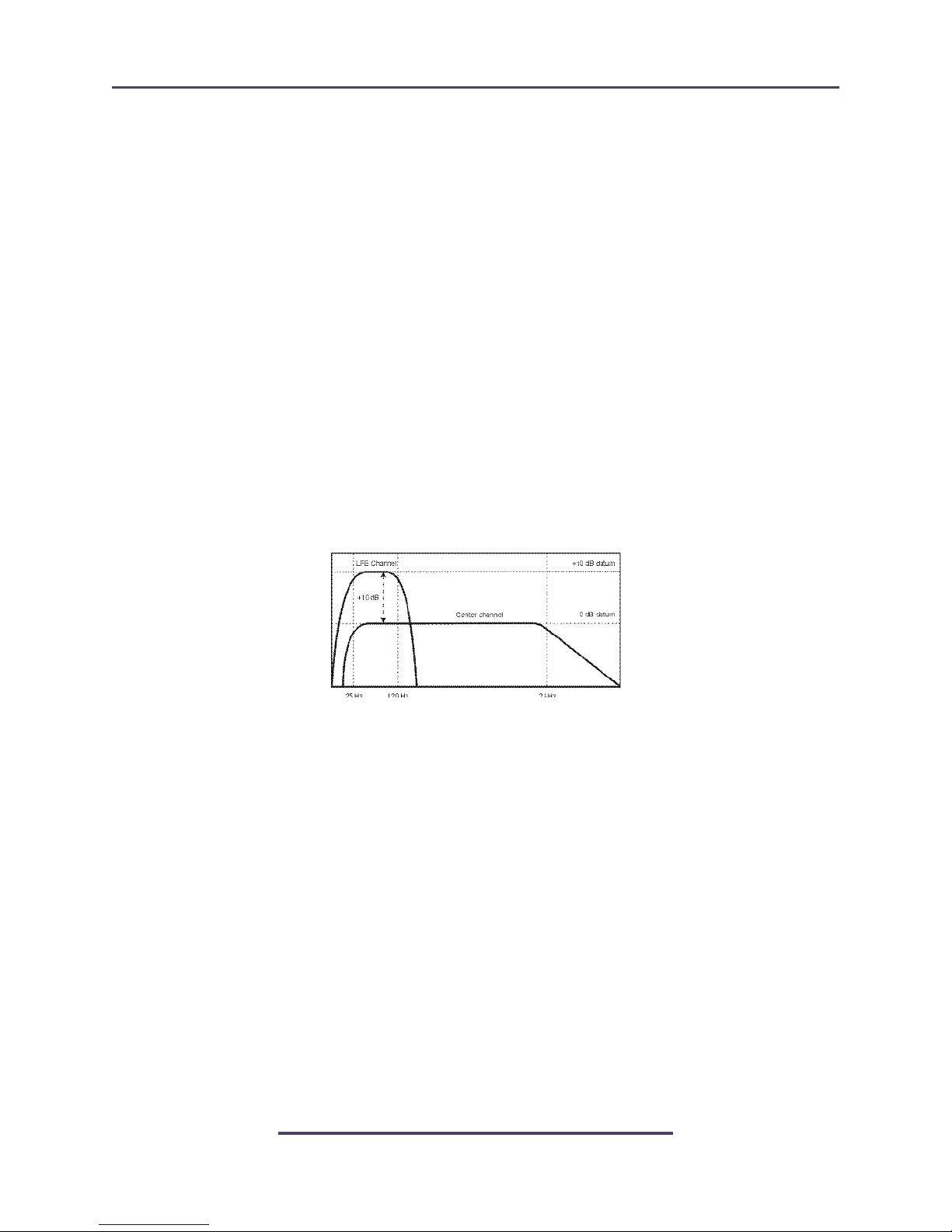
For 5.1 channel mixing, the subwoofer is required to apply 10dB of gain to the signal applied to it. This means that if the reference SPL of the main channels is set to 79dBSPL/
C/Slow, then the subwoofer is set to 89dBSPL/C/Slow. This is based on the long-standing practice in film to allow an extra 10dB of headroom in the Low Frequency Effects
(LFE) channel and was originally required by optical and magnetic tracks that could not
pass high-level low frequency information without severe overload. Modern 5.1 systems
no longer have a headroom issue, but for compatibility with industry practice and legacy
material, the increased reproduction level of the subwoofer is maintained.
It is strongly recommended that this adjustment be made with a real-time analyzer (RTA)
due to constraints of frequency response of typical SPL meters. The procedure is simple:
after calibrating the main channels, apply pink noise to the Center channel and note the
average level. Next, apply pink noise though the LFE channel to the subwoofer and adjust
its level so that it has 10dB of additional mid-band level as compared to the Center channel.
The desired relationship between Center and Subwoofer is shown below
Note that this is a real-time analyzer display of the response of a typical film mixing stage.
Due to the large distance from the speakers to the mixer, there is a natural roll off above
2 kHz (described in SMPTE 202M, and sometimes called the "X-curve.") In small mixing
and control rooms this response would be flat.
Once the alignment of all channels is complete, play some content through the system and
listen to make sure things sound normal. Never underestimate the effectiveness of taking a
listen to known content to make sure that things are really what they seem.
26
Page 33

Linear Acoustic UPMAX v4 User Guide Troubleshooting
Chapter 5: Troubleshooting
The Linear Acoustic UPMAX v4 is a very stable and reliable unit, and most problems can
be traced back to mis-wiring causing incorrect signals to be applied to the unit, or more
than likely mis-configuration. In an effort to speed troubleshooting, some common problems and solutions are described below.
5.1 Problems and Possible Causes
One of the best troubleshooting features of the UPMAX v4 is the hard-bypass of the audio
signals. This is useful because it allows instant removal of the unit from the signal path.
Hard-bypass can be accomplished two ways, the simplest being to remove AC power from
the unit. A less dramatic way to accomplish the same result is to access the System Options
menu and enable Master Bypass. If you are unsure of what is happening in a particular system, simplifying the signal path is a good start and will help isolate problems quickly.
5.1.1 Unit won’t power on
Check to make sure that the unit is connected to a live outlet (it happens...). If proper AC
voltage is being applied to the unit, remove power and check the fuse (the IEC inlet module has a fuse compartment that can be carefully opened with a small screwdriver). If the
fuse is blown there is a spare in the holder. Install the replacement fuse, re-insert the fuse
carrier, and re-apply power.
NOTE: Replace fuses only with the same size and rating: 5mmx20mm T1AL (250V)
5.1.2 Output Audio Clicks and Pops
This could indicate that the AES Reference is missing or at the wrong sample rate (the unit
expects to be locked to 48kHz). The unit is designed to default to an internal 48kHz reference in case the external reference is removed. This allows audio to continue, but the
outputs may be asynchronous with the rest of the plant. The solution is to make sure that
the reference is connected.
It could also mean that audio applied to the unit is not properly referenced, or that the
equipment that the unit is feeding is not properly referenced. Using the master bypass
function of the unit is a helpful way to troubleshoot this issue.
27
Page 34

Linear Acoustic UPMAX v4 User Guide Troubleshooting
5.1.3 Unit is Not Upmixing
From the main output screen, make sure that Upmix=On is shown. If not, press the joystick knob to alternate between upmix on/off.
Next, make sure that Center Width is between 0% and 33% and Surround Depth is 100%.
Adjusting these controls can set the surroundfield back to stereo. If Center Width is set to
100% (Center from Lf/Rf) and Surround Depth is set to 0% (Surround from LfRf), the
output signal will be stereo! Normally, these adjustments are Center = 0% and Surround
= 100%.
Lastly, if upmix is on but the unit is still is not upmixing, make sure that the unit is not in
Master Bypass (relay bypass) under the I/O menu.
5.1.4 Cannot Manually Control Upmixing
The unit may be set to respond to GPI or metadata commands. Access the I/O menu and
turn GPI control off.
5.1.5 Analog Outputs Have Noise
Ensure that the system has been set with proper gain structure. This means adjusting the
power amplifiers or powered speakers first, UPMAX v4 channel trims second, and volume
control last. Not following this will cause unnecessary increase of the noise floor and will
impact overall dynamic range. If the Master Volume is set to -40 for normal listening, the
system is not adjusted properly! Consult Chapter 4 for more detailed alignment instructions.
28
Page 35

Linear Acoustic UPMAX v4 User Guide Specifications
Chapter 6: Specifications
Figure 6-1 Electrical
Processing
Structure
Algorithm
Options
Headphone Output
Frequency
Response
Level
Connector
Analog Monitor Output
Frequency
Response
Level
Dynamic Range
Connector
5.1 channel main path plus LoRo/LtRt downmix
UPMAX®: 5.1-channel upmixing, automatic bypass of discrete content
Option 01: Remote Volume Control
20 Hz–20 kHz, 1 dB (upmix=Off)
+12 dBu maximum
1/4-in (6.35-mm) front panel jack with volume control
20 Hz–20 kHz, 1 dB, Upmixing Off
4dBu @-20dBFS, +24dBu into 600 Ohms @0dBFS
Greater than 85dB
DB25-F, pinout below
Digital I/O
Digital Audio I/O
Ethernet
GPI/O Parallel
Control Port
Metadata Input
Reference
HD/SD-SDI
Auto-Sensing I/O
All inputs are unbalanced, 75-, with internal termination
1-2, 3-4, 5-6, 7-8 use BNC-F connectors
Signal levels per SMPTE 276M/ AES-3ID-2001
100 BASE-T via RJ-45 connector
DB9-F connector, 0–5 V TTL levels
DB9-F connector, 115 kbps, pinout per SMPTE 207M (RS-422/485)
Interfaces directly with Dolby Metadata (SMPTE RDD6)
48 kHz via AES 1 or SDI input
De-embed up to 16 audio channels from SDI, process and re-embed up to 16 channels
Signal levels per SMPTE 292M /259M
Supports SMPTE 2020 A and B VANC metadata
Supports up to 1080i/60/59.94/50 Hz
29
Page 36

Linear Acoustic UPMAX v4 User Guide Specifications
Table 6-1 Physical
Dimensions
Net Weight
Environmental
Power Requirements
1RU
H = 1.75 in (45 mm) W = 19 in (483 mm) D = 11.5 in (293 mm)
6 lb (2.72 kg) approximate
Operating: 0 – 50ºC
Non-operating: -20 – 70ºC
Dual redundant auto-sensing power supplies, each rated at
100–240 VAC, 50–60 Hz, 35 W maximum
Latency
Latency is fixed regardless of surroundfield settings.
Table 6-2 Fixed latency for different signal paths
Function Latency
Main Out
Downmix Out LoRo 5 msec
Downmix Out LtRt 11 msec
7 msec, SRC Byp Off
4.6msec, SRC Byp On
30
Page 37

Linear Acoustic UPMAX v4 User Guide Specifications
Connector Pinouts
Table 6-3 Analog I/O (DB25-F)
Pin Function Pin Function
1 Ch 8 Ro/Rt + Out 14 Ch 8 Ro/Rt - Out
2 Ch 8 Ro/Rt Gnd 15 Ch 7 Lo/Lt + Out
3 Ch 7 Lo/Lt - Out 16 Ch 7 Lo/Lt Gnd
4 Ch 6 Rs + Out 17 Ch 6 RS - Out
5 Ch 6 Rs Gnd 18 Ch 5 Ls + Out
6 Ch 5 Ls - Out 19 Ch 5 Ls Gnd
7 Ch 4 Subwoofer + Out 20 Ch 4 Subwoofer - Out
8 Ch 4 Subwoofer Gnd 21 Ch 3 Center + Out
9 Ch 3 Center - Out 22 Ch 3 Center Gnd
10 Ch 2 Right + Out 23 Ch 2 Right - Out
11 Ch 2 Right Gnd 24 Ch 1 Left + Out
12 Ch 1 Left - Out 25 Ch 1 Left Gnd
13 NC
DB-25 Female connector with an electrical pinout that matches the Tascam DA-88 format. Signals are
+4dBu nominal with a digital input signal of -20dBFS, and have a maximum balanced output of
+24dBu into 600 ohms.
31
Page 38

Linear Acoustic UPMAX v4 User Guide Specifications
Table 6-4 Metadata Input Port Pinout
Pin Connection
1 Shield
2 TX A asynchronous data out –
3 RX B asynchronous data in +
4 Ground
5NC
6 Ground
7 TX B asynchronous data out +
8 RX A asynchronous data in –
9 Shield
DB9-F connector with full-duplex RS-485 protocol running at 115 kbps. Pinout is compatible with
SMPTE 207M. Pin-for-pin compatible with Dolby Metadata (SMPTE RDD6)
Table 6-5 Remote Volume Control Port (DB9-F)
Pin Connection
1 Mute (GPI A)
2 Return to Ref (GPI B)
3 GPO A (High when Muted)
4 GPO B (High when at Ref)
5 Ground
6 Encoder Phase A Input
7NC
8 Encoder Phase B Input
9 +5V, 200 mA Max
Female DB-9 connector accepts TTL level controls, active Low. GPIs require a momentary contact
closure to activate their assigned function. The 5-V output for external GPO indicators is limited by a
self-resetting fuse.
32
Page 39

Linear Acoustic UPMAX v4 User Guide Specifications
Table 6-6 GP I/O Parallel Control Port (DB9-F)
Pin Function
1 GPI 1 (Active Low)
2 GPI 2 (Active Low)
3 GPI 3 (Active Low)
4 GPI 4 (Active Low)
5 Ground
6 GPO 1 (+5V TTL)
7 GPO 2 (+5V TTL)
8 GPO 3 (+5V TTL)
9 GPO 4 (+5V TTL)
Female DB-9 connector accepts TTL level controls, active Low.
Regulatory
North America: Designed to comply with the limits for a class A digital device pursuant to Part 15 of
the FCC rules (CFR). Designed for U.S. and Canadian listing with UL.
Europe: Designed to comply with the requirements of Low Voltage Directive 73/23/EEC and EMC
Directive 89/336/EEC. Designed for RoHS and WEEE compliance.
33
 Loading...