

Page 1

Model LA-5448
AC-3 Frame Synchronizer and Rate Shaper
User’s Guide
Page 2

Page 3
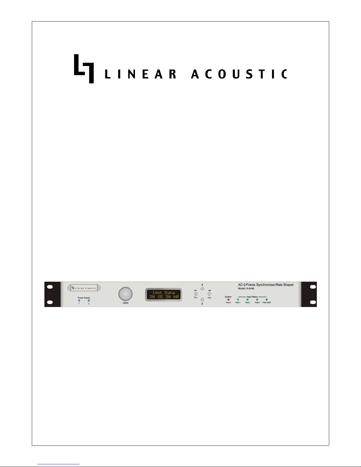
Model LA-5448
AC-3 Frame Synchronizer and Rate Shaper
User Guide
Release Date: February, 2006
Software Version: 01.00.21 and later
Linear Acoustic Inc.
Phone: 888-292-3117
FAX: 717-735-3612
email: www.LinearAcoustic.com
Page 4

Warranty Information
DISCLAIMER OF WARRANTIES: Products manufactured by Linear Acoustic Inc. are warranted against defects in material and workmanship for a period of two (2) years from the date
of purchase. THERE ARE NO OTHER IMPLIED OR EXPRESS WARRANTIES AND
NO WARRANTY FOR MERCHANTABILITY OR FITNESS FOR A PARTICULAR
PURPOSE.
During the warranty period Linear Acoustic Inc. will repair, or at our discretion replace, components which prove to be defective, provided the unit is returned, shipped pre-paid to us directly
with a return authorization (RA) number clearly marked on the packaging. Please note, this
RA number must be present or package will be refused and returned to sender.
All requests for repairs MUST include the unit serial number to ensure quick and accurate service.
DEFECTS CAUSED BY UNAUTHORIZED MODIFICATIONS, MISUSE OR ACCIDENTS, UNAUTHORIZED CUSTOMER REPAIRS, OR ANY FURTHER DAMAGE
CAUSED BY INADEQUATE PACKAGING FOR SERVICE RETURN ARE NOT COVERED BY THIS WARRANTY.
PLEASE SAVE THE SHIPPING CARTON AND ALL PACKING MATERIALS. FAILURE TO RETURN UNIT IN ORIGINAL SHIPPING CARTON AND PACKING
MATERIALS WILL RESULT IN A CHARGE FOR NEW SHIPPING MATERIALS.
LIMITATION OF PERIOD OF ACTION ON CONTRACT: No action, regardless of form,
arising out of the transactions under this agreement may be brought by buyer, its successors,
agents and/or assigns, more than two years from date of purchase.
LIMITATION OF LIABILITY: It is understood and agreed that Linear Acoustic’s liability
whether in contract, in tort, under any warranty, in negligence or otherwise shall not exceed the
cost of repair or replacement of the defective components and under no circumstances shall
Linear Acoustic be liable for incidental, special, direct, indirect or consequential damages, or loss
of use, revenue or profit even if Linear Acoustic or its agents have been advised, orally or in
writing, of the possibility of such damages.
StreamStacker, upMAX, AutoNorm, metaMAX, CrowdControl and AEROMAX-TV are registered trademarks of Linear Acoustic Inc., all other trademarks remain the property of their
respective owners.
Page 5

Linear Acoustic LA-5448 AC-3 Frame Synchronizer/Rate Shaper User Guide
Table of Contents
List of Figures.......................................................................................................................................... vii
Chapter 1: Introduction...................................................................................................................5
1.1 Principles of Operation..........................................................................................5
1.2 Location of LA-5448..............................................................................................6
1.3 Future Updates........................................................................................................6
1.4 Warranty and Feedback .........................................................................................7
Chapter 2: Connections..................................................................................................................9
2.1 Unpacking and Inspection ....................................................................................9
2.2 Installation ...............................................................................................................9
2.3 Rear Panel ..............................................................................................................10
2.3.1 Connection Ports .................................................................................10
2.4 Quick Setup Notes ...............................................................................................11
Chapter 3: Applications................................................................................................................13
3.1 AC-3 (Dolby Digital) Notes................................................................................15
3.1.1 Output Mode ........................................................................................15
3.1.2 Multiplexer Timing Issues...................................................................15
Chapter 4: Menus..............................................................................................................................17
4.1 Main Menu Level..................................................................................................19
4.1.1 Status Menu...........................................................................................19
4.1.2 Statistics Menu ......................................................................................19
4.1.3 Setup Menu ...........................................................................................19
Chapter 5: Troubleshooting.......................................................................................................21
5.1 Problems and Possible Causes............................................................................21
5.1.1 Status Lights are Green, but Display Shows Random Data ..........21
5.1.2 Program 4/REF Input LED is Amber.............................................21
v
Page 6

Linear Acoustic LA-5448 AC-3 Frame Synchronizer/Rate Shaper User Guide
5.1.3 Unit Produces 448 kbps Output, but it is Silent..............................21
Chapter 6: Specifications............................................................................................................23
vi
Page 7

Linear Acoustic LA-5448 AC-3 Frame Synchronizer/Rate Shaper User Guide
List of Figures
1-1 LA-5448 Frame Synchronizer/Rate Shaper Block Diagram ........................................................ 6
2-1 Rear Panel ...........................................................................................................................................10
3-1 LA-5448 processing three individual AC-3 streams, rate shaping disabled ..............................13
3-2 LA-5448 processing three separate streams, rate shaping enabled. ...........................................14
vii
Page 8

Linear Acoustic LA-5448 AC-3 Frame Synchronizer/Rate Shaper User Guide
Chapter 1: Introduction
The Linear Acoustic LA-5448 AC-3 Frame Synchronizer and Rate Shaper accepts
three independent AC-3 streams and synchronizes them to a reference signal applied
to the fourth input. This fourth input will accept 48kHz AES signals containing
PCM or AC-3. If an AC-3 signal is applied, it will also be processed as a fourth program, but as it is also reference, it must be a stable 48kHz source (AC-3 data rate does
not matter).
The Linear Acoustic LA-5448 has the following features:
• High density frame synchronization of AC-3 bitstreams
• Silent frame mode replaces errored or missing AC-3 frames with known good
versions
• Rate shape mode allows output data rate to be fixed at 448 kbps while the input
data rate can vary between 96 kbps and 448 kbps
• Features combine to allow artifact free, stable switching of pre-encoded content
(i.e. commercial insertion) while maintaining critical AC-3 parameters
• Dual, redundant power supplies and hard-bypass for mission critical applications.
1.1 Principles of Operation
Figure 1-1 shows the internal audio path of the LA-5448.
It should be noted that this diagram is a general representation of signal flow. Please
consult the appropriate section of this manual for specific functionality.
5
Page 9

Linear Acoustic LA-5448 AC-3 Frame Synchronizer/Rate Shaper User Guide Introduction
2
4
Bypass
PGM 1
PGM 1
PGM 2
PGM 3
Ref/PGM 4
AES
Rcvr
AES
Rcvr
AES
Rcvr
AES
Rcvr
PLL/
Clock
Frame
Sync
Frame
Sync
Frame
Sync
Frame
Sync
Rate
Shape
Rate
Shape
Rate
Shape
Rate
Shape
Delay
Delay
Delay
Delay
Format &
AES Tx
Format &
AES Tx
Format &
AES Tx
Format &
AES Tx
Bypass
Bypass
Bypass
Out
PGM
Out
PGM 3
Out
PGM
Out
Figure 1-1 LA-5448 Frame Synchronizer/Rate Shaper Block Diagram
1.2 Location of LA-5448
The Linear Acoustic LA-5448 Demultiplexer/Splicer is best located near network
satellite receivers or just prior to a multiplexer. In some cases, it maybe located near
AC-3 encoders such as a Dolby DP-569. As it will likely be in a transmission environment, dual redundant power supplies and hard relay bypass are provided for trouble free operation.
1.3 Future Updates
Software updates may become available in the future to add additional features and
performance. Updates will utilize the serial port to accomplish the installation of upgraded software, and a loader application will be provided for this purpose.
(FPUI, I/O , PSU Mon,
CPU
System Control)
6
Page 10

Linear Acoustic LA-5448 AC-3 Frame Synchronizer/Rate Shaper User Guide Introduction
1.4 Warranty and Feedback
Please take a moment to fill out the warranty card included with the unit and drop
it in the mail. This will enable us to contact you if there are any software or documentation issues. Also, we are very interested in your feedback. This unit was designed based on feedback gathered from many broadcast engineers and it will evolve
further thanks to ongoing suggestions and comments from users such as you.
We look forward to hearing from you!
7
Page 11

Linear Acoustic LA-5448 AC-3 Frame Synchronizer/Rate Shaper User Guide Introduction
8
Page 12

Linear Acoustic LA-5448 AC-3 Frame Synchronizer/Rate Shaper User Guide
Chapter 2: Connections
This chapter covers all required connections for the LA-5448.
2.1 Unpacking and Inspection
Before unpacking the unit, inspect the outer carton for shipping damage. If the carton shows damage, inspect the unit in those areas. Please save the carefully designed
shipping carton and packing materials. In the unlikely event that the unit needs to be
returned to the factory, alternate cartons or packing materials may not be adequate
and can cause damage not covered by warranty.
The following essential items are provided with the unit:
• Two power cords (style to match shipping location).
• Small bag with replacement fuses and a handy permanent marker.
• This manual.
• Warranty information: Please fill out and return the warranty card to Linear
Acoustic to ensure your software and documentation are kept up to date.
2.2 Installation
StreamStacker LA-5448 installation requires:
• One standard rack space units with ADEQUATE VENTILATION (the unit uses
convection cooling via vents on the left and right sides of the unit);
• standard 75 BNC cables for digital signal connections;
To connect to digital equipment with 110 XLR connectors, we strongly recommend
the use of impedance-matching transformers (baluns) which are available from Canare,
Neutrik and other manufacturers. We know it is tempting to use shortcuts, and they
will sometimes work just fine, however failure of such approaches are usually random
and always seem to happen during the most expensive programming. We encourage
the use of the inexpensive and widely available baluns, especially in a transmission environment.
9
Page 13

Linear Acoustic LA-5448 AC-3 Frame Synchronizer/Rate Shaper User Guide Connections
2.3 Rear Panel
The rear panel of the Linear Acoustic LA-5448 contains all signal and power I/O.
WARNING: Replace fuses only with the same type and rating
2.3.1 Connection Ports
All of the LA-5448’s connections are on the rear panel and are described in detail below.
See Chapter 5: Specifications for specific pinouts.
Figure 2-1 Rear Panel
•Remote: This RS232/485/422 port is used for software upgrades as well as serial
remote control of the unit.
• Status: This is the GPI/O connection for parallel control of the unit. There are
four GP Inputs and four GP Outputs whose function, polarity, and type (i.e. held
or momentary) are adjustable via the front panel user interface. FUTURE
• Main Inputs (PGM 1-PGM 3): Connect the AC-3 signals that are to be processed to these connectors. During power on and in the unlikely event of failure,
these inputs will be hard relay bypassed to the corresponding output connectors
located below each of them.
• REF/PGM 4: Apply 48 kHz AES reference, either PCM or AC-3.
WARNING:
A reference AC-3 signal MUST be connected to REF/PGM 4 at all times for proper
operation. Plain AES reference can also be used.
• Main Out Pgm 1-4: Main AC-3 (Dolby Digital) programs one through four.
During boot up or in the event of failure, the Main Input connector directly
above each output will be hard relay bypassed to it.
NOTE: Front panel LEDs indicate input signal condition: Off=No Signal present,
Orange=AES sync detected but no AC-3, Green=OK.
10
Page 14

Linear Acoustic LA-5448 AC-3 Frame Synchronizer/Rate Shaper User Guide Connections
2.4 Quick Setup Notes
The LA-5448 requires only minimal setup to be up and running.
• Apply power to BOTH IEC AC power inlet modules.
• Note that once booted (~ 5 seconds), the front panel will display “No Reference” if no connections have been made to the rear panel.
• Connect a locally referenced 48kHz AC-3 signal (data rate or other parameters
do not matter) or an AES reference to the REF/PGM4 input
• Verify that the front panel indicator shows either a Green (AC-3) or Amber
(AES) signal has been detected on Input 4.
• Connect one or more AC-3 signals to be processed to the remaining PGM 1PGM 3 connectors
• Frame synchronized, rate shaped (to 448kbps) versions of these programs will be
produced at the corresponding Main Out Pgm 1-PGM 3 connectors.
11
Page 15

Linear Acoustic LA-5448 AC-3 Frame Synchronizer/Rate Shaper User Guide Connections
12
Page 16

Linear Acoustic LA-5448 AC-3 Frame Synchronizer/Rate Shaper User Guide
f
Chapter 3: Applications
The LA-5448 is intended to be used in an emission (transmission) environment. This
chapter shows several applications of the system as it is intended to be used. Of
course other applications are possible:
• Frame synchronizer for multiple AC-3 streams, no rate shaping
• Frame synchronizer plus rate shaping for multiple AC-3 streams
Satellite
384
kbps
AC-3
384 kbps
Local 48 kHz AES Re
(AC -3 or P CM )
X
AC-3 448 kbps
Synchronized to Local
Reference
AC-3 192 kbps
448
192
kbps
kbps
Multiplexer
Figure 3-1 LA-5448 processing three individual AC-3 streams, rate shaping disabled
Figure 3-1 above shows three sources being frame synchronized to a local plant reference signal. Data rates at the output are unchanged, but errors can be mitigated by
enabling Silent Frame mode.
13
Page 17

Linear Acoustic LA-5448 AC-3 Frame Synchronizer/Rate Shaper User Guide Applications
f
Satellite
VTR/Server
AC-3
384 kbps
AC-3
448 kbps
AC-3 384/448 kbps
Synchronized to Local
Reference, fixed at 448 kbps
AC-3 192 kbps
448
448
kbps
kbps
Multiplexer
448
kbps
AC-3
384 kbps
Local 48 kHz AES Re
(AC -3 or PC M )
X
Figure 3-2 LA-5448 processing three separate streams, rate shaping enabled.
Figure 3.2 shows multiple AC-3 sources being frame synchronized to a local plant
reference as well as being rate shaped to a constant 448 kbps output data rate. Also
shown is a “crash switch” between two AC-3 sources that will be cleaned up and kept
at a constant data rate by the LA-5448. This is useful for commercial insertion applications.
14
Page 18

Linear Acoustic LA-5448 AC-3 Frame Synchronizer/Rate Shaper User Guide Applications
3.1 AC-3 (Dolby Digital) Notes
The maximum data rate that is supported by the LA-5448 is 448 kbps. Rates higher
than this will be displayed as an error condition. When stream shaping is turned on,
no changes are made to AC-3 content. All metadata and audio parameters are passed
exactly as originally encoded with the exception that the data rate will now be fixed
at 448 kbps.
Several additional parameters and configurations are described below.
3.1.1 Output Mode
Typical external AC-3 encoders (i.e. Dolby DP569) or other AC-3 sources may have
several selections for output mode, which simply determines where inside an AES
pair the relatively tiny AC-3 data packets are carried. It does not matter which selection is chosen as long as the LA-5448 and the encoder match. The default for the LA5448 is Pro-32, the default for most known professional equipment that generates or
passes AC-3. The result of mis-setting this is that the output audio will mute.
3.1.2 Multiplexer Timing Issues
Tandberg encoders supply an AES reference signal that may be in the form of a fifth
wire with a BNC connector attached (later models), or it may be an XLR connector,
possibly of the opposite sex (i.e. an XLR Female) requiring an AES balun. There also
may be a menu setting to enable this reference output (automatically enabled in later
models). This reference MUST be used to drive the local AC-3 encoder’s reference
input. It is NOT necessarily the same as plant reference as it is derived from the encoder’s internal 27MHz clock. Save some headaches and lost sleep, and use this provided connection!
NOTE: Tandberg encoders provide an external reference output which MUST be
used to lock the local AC-3 encoder.
15
Page 19

Linear Acoustic LA-5448 AC-3 Frame Synchronizer/Rate Shaper User Guide Applications
16
Page 20

Linear Acoustic LA-5448 AC-3 Frame Synchronizer/Rate Shaper User Guide
Chapter 4: Menus
This chapter discusses how to use the front panel LED interface to access the menus. Most
of it is rather obvious, and a bit of experimentation will quickly make you comfortable navigating through the submenus. The menus and submenus are structured to access more
complex functionality as you go deeper into the hierarchy.
The following two pages show the menu structure for the LA5124. All up/down access is
by the up/down front panel buttons, all left/right access is by the left/right (Prev/Next)
front panel buttons, and parameter changes (where applicable) are by the use of the rotary
encoder knob. When a parameter is changed, an asterisk (*) will be displayed next to the
parameter denoting that it has changed and that in order for this change to be stored, the
right (Next) front panel button must be pressed. To continue without storing the change,
press the left (Prev) front panel button.
Like all of our products, when in doubt you can simply use the Left Arrow (Prev) to back
out towards the Main menu level.
17
Page 21
Linear Acoustic LA-5448 AC-3 Frame Synchronizer/Rate Shaper User Guide Menus
Linear A coustic
LA5448 V 01.00.21
P1 P2 P3 P4
384 + 192 + --- + 448
PGM 1 Status
384kb 3/2L 448kb
PGM 2 Status
192kb 2/0 448kb
PGM 3 Status
----- ---- P C M
PGM 4 Status
448kb 3/2L 448kb
Statistics
Down To View
Firm w are Version
5448 0025
D e v ice O p tio n s
None
PGM 1
CRC errors: 0
PGM 2
CRC errors: 0
PGM 3
CRC errors: 0
PGM 4
CRC errors: 0
LA5448 Setup
Down To View
Down To View
PGM 1 Form at
Pro 32-Bit
PGM 2 Form at
Pro 32-Bit
PGM 3 Form at
Pro 32-Bit
PGM 4 Form at
Pro 32-Bit
Output Format
Pro 32-Bit
I/O
System
Down To View
Set To Defaults
Set: G PIs
PGM 1 Delay
32 m Sec
PGM 2 Delay
32 m Sec
PGM 3 Delay
32 m Sec
Valid Bit
Valid
Silent Frame
Enable
Stream Shaper
Enable
18
Page 22

Linear Acoustic LA-5448 AC-3 Frame Synchronizer/Rate Shaper User Guide Menus
4.1 Main Menu Level
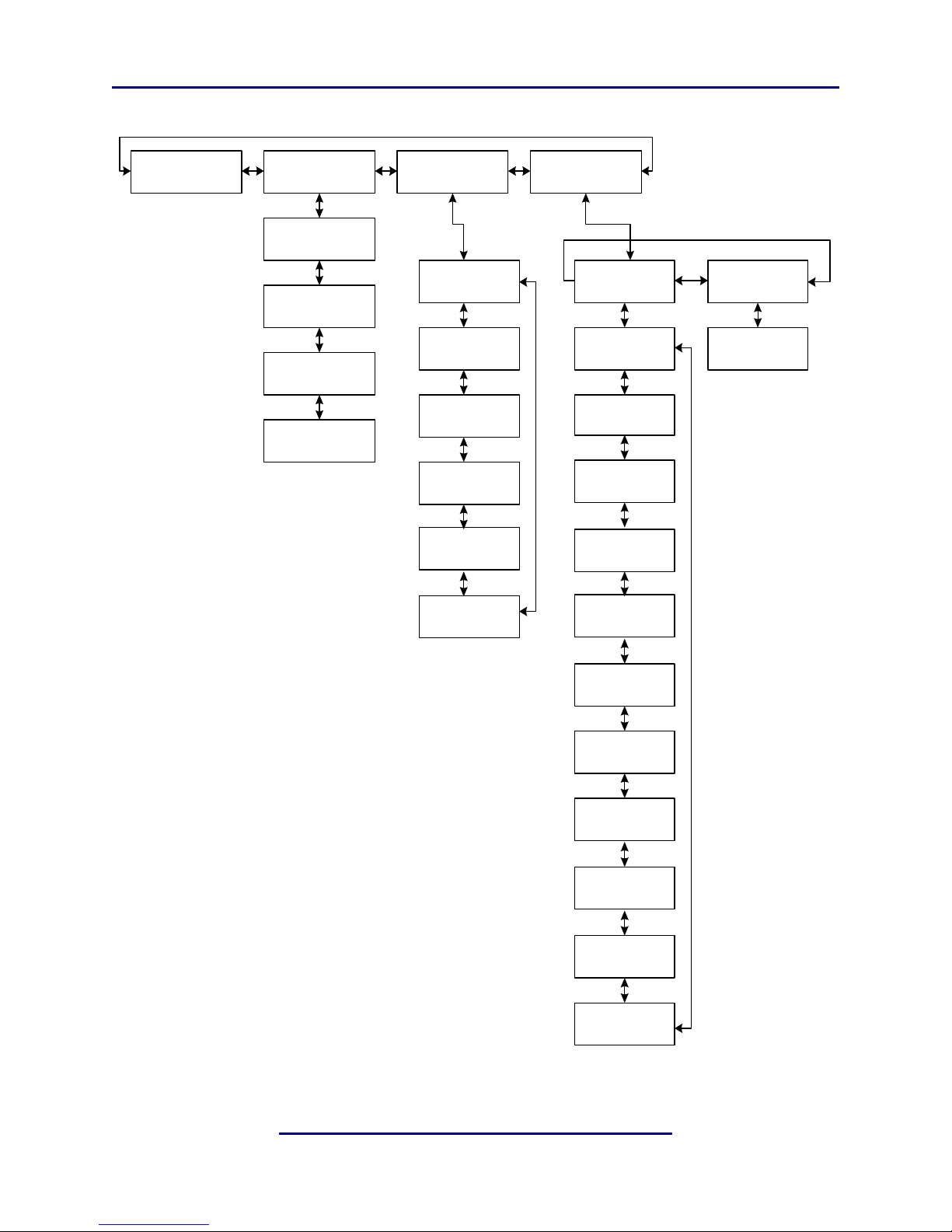
Referring to the menu tree on the preceding page, it can be seen that the Main Menu level
can be scrolled through using either the left or right arrows. The choices are: Version, Status, Statistics, and Setup, each of which have sub menus (except the version screen). The
submenus can be accessed by pressing the down arrow. Note that both the Status and Statistics screens are informational and have no adjustments.
4.1.1 Status Menu
Upon booting, the Version screen in briefly displayed then switched to the Status Menu.
The Status Menu shows the data rate for the AC-3 signals applied to each of the four Main
Inputs, and displays dashes (----) for programs that are not present.
Pressing the Down arrow will step through each of the four main input programs,
showing the input data rate, followed by the audio coding mode (acmod) metadata
parameter, followed by the output data rate. If Stream Shaping is disabled, the input
and output data rates will match. If Stream Shaping is enabled, the output data rate
will be fixed at 448 kbps.
4.1.2 Statistics Menu
The Statistics menu provides more detailed information about the health of each of the
input signals applied to the LA-5448. The main status LEDs on the front panel give the
first indication of trouble when illuminated red, while further details about the error condition can be found under this menu. Currently, the CRC of the AES carrier is counted
and displayed and future revisions will expand this to show details of the AC-3 CRCs contained within each AES input.
As a general rule of thumb, the AES CRC indicates interface issues stemming from the corruption of the physical AES interface. These types of errors are most likely due to problems such as clocking, termination, or asynchronous switching. The AC-3 CRC is useful
for determining upstream issues where the physical interface may be valid but clicking or
popping might be heard after decode as the AC-3 packets are being damaged. The cause
of an inner-interface issue such as this can stem from many things, but one likely suspect
is a satellite receiver that is losing lock due to rainfade or other RF issues- the AES carrier
may still be present as it is generated locally, but its AC-3 payload could be damaged or
missing.
4.1.3 Setup Menu
This menu contains settings for the main digital audio I/O as well as a method to restore
factory defaults. To adjust a particular parameter, simply rotate the rotary encoder knob
until the desired value is displayed. An asterisk (*) is also displayed noting that the change
will be made and stored to memory when the Right (Next) front panel button is pressed.
19
Page 23

Linear Acoustic LA-5448 AC-3 Frame Synchronizer/Rate Shaper User Guide Menus
I/O Menu
The AES input formats of the LA5124 can be set to Professional 32-Bit, Consumer (also
32-bit with the Pro/Consumer mode bit set to Consumer), 16-Bit Channel 1, and 16-Bit
channel 2. These can be independently adjusted on an input-by-input basis, and defaults
to Pro 32-Bit. Note that most all gear is set to 32-bit mode, and only in rare cases does the
pro/consumer bit matter.
The format of all of the outputs can be varied between Pro 32-Bit and Consumer. This is
a single setting for all outputs and defaults to Pro 32-Bit. We have found that the Aastra/
Harris Flexicoder requires this setting to be Consumer, but that is the only case of which
we are aware.
Delays can be independently set for each of the inputs, and are adjustable in 32 msec
(single AC-3 frame) increments up to about four seconds.
The AES output validity bit can also be set, and is defaulted to “Invalid” to indicate that
the signals present in the AES stream are not suitable for direct conversion back to analog.
As the interpretation of this bit varies by manufacturer, we have made it adjustable to
match any situation.
Silent frame mode is enabled by default and has the function of keeping a continuous
AC-3 stream flowing from each output of the LA-5448 in case of input error or loss.
If a corrupt AC-3 frame is detected, the last good frame is repeated, then silent frames
equal to the data rate and channel mode (acmod) of this last good frame are output
until valid error free AC-3 frames return. Note that if Silent Frame mode is required
and automatically enabled for Stream Shaping functionality.
Stream Shape mode is enabled by default and has the function of keeping the output
data rate fixed at 448 kbps regardless of the input data rate. No audio or metadata is
affected by this. When combined with frame synchronization and silent frame, it allows AC-3 streams of the same or different rates to be switched upstream via an AES
router or other synchronous or asynchronous switch and a single-rate error-free will
be output synchronized to plant reference.
System Menu
Under this menu, the LA5124 can have all of its parameters reset to factory defaults.
20
Page 24

Linear Acoustic LA-5448 AC-3 Frame Synchronizer/Rate Shaper User Guide
Chapter 5: Troubleshooting
The Linear Acoustic LA-5448 is a very stable and reliable unit, and most problems can be
traced back either to mis-wiring causing incorrect signals to be applied to the unit or more
than likely to mis-configuration. In an effort to speed troubleshooting, some common
problems and their solutions are described below.
5.1 Problems and Possible Causes
Most problems can be traced back to the input signals applied to the LA-5448. Experience
has shown many early high definition satellite IRDs used for the reception of network signals to be rather unreliable when presented with changing transport streams. The input status menus on the LA-5448 are very useful for tracking down data rate and audio coding
mode discontinuities, as well as for monitoring CRC errors.
5.1.1 Status Lights are Green, but Display Shows Random Data
To recap, the LEDs have three states: Off = no signal applied, Red= AES carrier detected
but AC-3 is not detected, Green = AES signal is present, correct data type marked. So how
is it that with all green LEDs that data can still be wrong? There are multiple places where
the contents of a typical AES signal are tagged with their identities. One is in the AES
header itself (unreliable), one is before the actual data (called the IEC header), and one is
in the data itself, in this case inside the AC-3 packets. Think of the LEDs detecting the first
two: AES presence, and IEC header present, while the display shows the last: AC-3
present.
Once common cause of this is directly attributable to satellite IRDs which will output a
blank AES stream with an IEC header that signifies AC-3, but with either a random or
blank audio payload (i.e. no AC-3 data is actually present). This can be caused by the receiver being set to an invalid or missing PID, or by the PID disappearing.
5.1.2 Program 4/REF Input LED is Amber
The reference signal applied is PCM and not AC-3. This is a perfectly acceptable condition,
and Amber is simply used to indicate that the input is valid, but is not AC-3 in nature. The
LA-5448 locks to the frequency of the reference input, and the payload is ignored. However, if the reference input is fed with an AC-3 signal, in addition to it providing the frequency reference for the unit, the signal will also be frame synchronized, have silent frames
inserted if necessary, and be rate shaped if desired.
5.1.3 Unit Produces 448 kbps Output, but it is Silent
Stream Shaper is enabled (and by requirement, so is silent frame), and the input for the
channel in question is either missing, or errored.
21
Page 25

Linear Acoustic LA-5448 AC-3 Frame Synchronizer/Rate Shaper User Guide Troubleshooting
22
Page 26

Linear Acoustic LA-5448 AC-3 Frame Synchronizer/Rate Shaper User Guide
Chapter 6: Specifications
Table 6-1 Electrical Specifications
Sampling Rate
Output Delay
Programs
Audio Resolution
Main Input Program 1-3
Program 4/Ref Input
Main Outputs (Pgm 1-4)
Processing
Remote (RS-232/485/422)
48 kHz (0.1%)
1.5 AC-3 frames, +/- 0.5 frames (48 msec, +/- 16 msec)
minimum, can be increased in 32 msec steps to provide up to
4 seconds of delay to match external equipment.
Up to four separate AC-3 programs
AC-3 Codec dependent, LA-5448 is transparent
75-Ohm BNC female connectors, per AES-3ID-1995/SMPTE
276M, internally terminated
48 kHz AES input, PCM or AC-3, can be used as a fourth processing channel. 75-Ohm BNC female connector, per AES3ID-1995/SMPTE 276M, internally terminated.
Four 75-Ohm BNC female connectors per AES-3ID-1995/
SMPTE 276M, with relay bypass from corresponding inputs
AC-3 frame synchronization, selectable silent frame insertion
upon input error or loss, selectable rate shaping: any input rate
up to 448 kbps will be output at a fixed 448 kbps
9-pin female D-connector
Status (GPIO) Port
Ethernet Port
Boot Time
TTL level, 9-pin female D-connector
RJ-45 female jack connector, 10/100 BASE-T
Less than 5 seconds
23
Page 27
Linear Acoustic LA-5448 AC-3 Frame Synchronizer/Rate Shaper User Guide Specifications
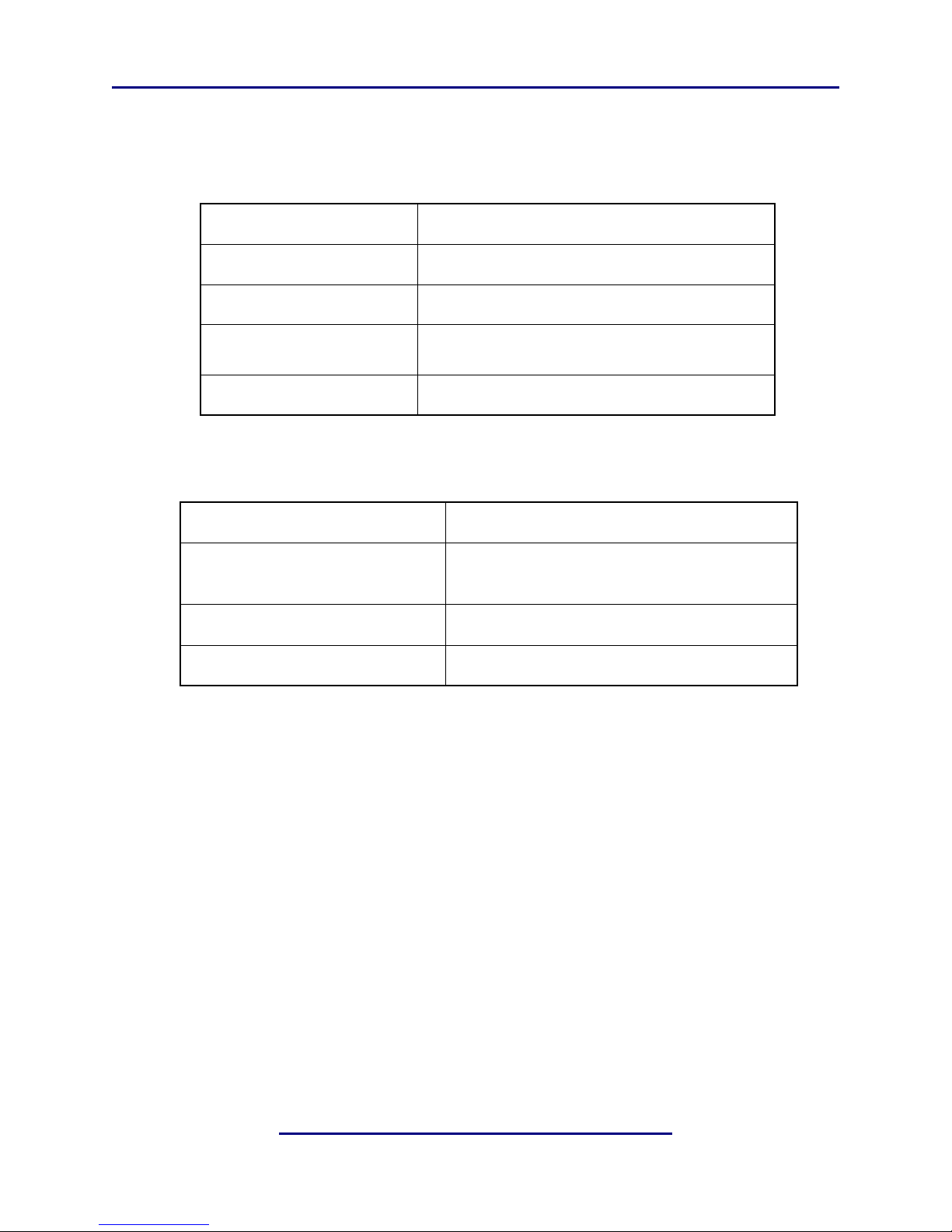
Table 6-2
Table 6-3 Mechanical Specifications
Dimensions
Net Weight
Shipping Weight
Power Requirements
Power Consumption
Table 6-4 Environmental Specifications
Operating Temperature
Non Operating Temperature
(Storage)
Humidity
EMC Radiation Limits
1.75 19 24 in (4.45 48.3 61 cm)
6 lb (12.6 kg) approx.
8 lb (15.75 kg) approx.
115/220 VAC, auto ranging, 50–60 Hz,
2 supplies for redundancy
35 W total maximum
0oC to 50oC, convection cooled
o
–20
C to +70oC
Up to 98% relative humidity, non-condensing
FCC Part 15 Class A, ICES-003
24
Page 28

Linear Acoustic LA-5448 AC-3 Frame Synchronizer/Rate Shaper User Guide Specifications
RS485/422/232 Port
9-pin female D-connector with full-duplex RS-485 protocol running up to 115 kbps. Pinout is compatible with SMPTE 207M.
Table 6-5 RS-485/422/232 Input Port Pinout
Pin Connection
1Shield
2TX A asynchronous data out –
3RX B asynchronous data in +
4Ground
5NC
6Ground
7TX B asynchronous data out +
Status (GPI/O) Port
9-pin female D-connector, TTL compatible levels.
Table 6-6 Status (GPI/O) Port Pinout
8RX A asynchronous data in –
9Shield
Pin Connection
1 GP Input 1
2 GP Input 2
3 GP Input 3
4 GP Input 4
5Ground
6GP Output 1
7GP Output 2
8GP Output 3
9GP Output 4
25
Page 29

Linear Acoustic LA-5448 AC-3 Frame Synchronizer/Rate Shaper User Guide Specifications
Ethernet Port
The Ethernet port is a standard RJ-45 female connector that supports 10 or 100BASE-T.
This connector is currently not active, but will be enabled in a future software release.
26
 Loading...