

Page 1
Release Date:
Linear Acoustic Inc.
Phone:
Web:
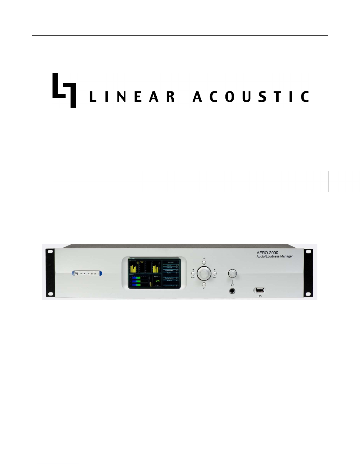
AERO.2000 Audio/Loudness Manager
User Guide
Software Version:
July, 2016 v2
3.15.26
and later
717-735-3611
FAX:
717-735-3612
www.LinearAcoustic.com
Page 2

AERO.2000 User Guide July 2016
1111 Warranty Information
Warranty Information
Warranty InformationWarranty Information
DISCLAIMER OF WARRANTIES: Products manufactured by Linear Acoustic are warranted
against defects in material and workmanship for a period of two (2) years from the date of
purchase. THERE ARE NO OTHER IMPLIED OR EXPRESS WARRANTIES AND NO WARRANTY
FOR MERCHANTABILITY OR FITNESS FOR A PARTICULAR PURPOSE.
During the warranty period Linear Acoustic Inc. will repair, or at our discretion replace,
components which prove to be defective, provided the unit is returned, shipped pre-paid to us
directly with a return authorization (RA) number clearly marked on the packaging. Please note,
this RA number must be present or package will be refused and returned to sender.
All requests for repairs MUST include the unit serial number to ensure quick and accurate
service.
1. DEFECTS CAUSED BY UNAUTHORIZED MODIFICATIONS, MISUSE OR ACCIDENTS,
UNAUTHORIZED CUSTOMER REPAIRS, OR ANY FURTHER DAMAGE CAUSED BY
INADEQUATE PACKAGING FOR SERVICE RETURN ARE NOT COVERED BY THIS
WARRANTY.
L16/1/18039
PLEASE SAVE THE SHIPPING CARTON AND ALL PACKING MATERIALS. FAILURE TO RETURN
UNIT IN ORIGINAL SHIPPING CARTON AND PACKING MATERIALS WILL RESULT IN A CHARGE
FOR NEW SHIPPING MATERIALS.
LIMITATION OF PERIOD OF ACTION ON CONTRACT: No action, regardless of form, arising out
of the transactions under this agreement may be brought by buyer, its successors, agents
and/or assigns, more than three years from date of purchase.
LIMITATION OF LIABILITY: It is understood and agreed that Linear Acoustic’s liability whether in
contract, in tort, under any warranty, in negligence or otherwise shall not exceed the cost of
repair or replacement of the defective components and under no circumstances shall Linear
Acoustic be liable for incidental, special, direct, indirect or consequential damages, or loss of
use, revenue or profit even if Linear Acoustic or its agents have been advised, orally or in
writing, of the possibility of such damages.
This product contains Audyne dynamic range processing and is manufactured under license.
This product optionally contains technologies from Dolby® Laboratories. Manufactured under
license from Dolby Laboratories. Dolby and the double-D symbol are trademarks of Dolby
Laboratories.
This product optionally contains Nielsen Watermarking technology and is manufactured under
license.
©2016 LINEAR ACOUSTIC INC. THE TELOS ALLIANCE. ALL RIGHTS RESERVED
Page ii
Page 3

AERO.2000 User Guide July 2016
L16/1/18039
Linear Acoustic, the “LA” symbol, UPMAX, AEROMAX, AERO.2000, AERO.air, AutoNorm,
MetaMAX, AutoMAX-II, AutoVoiceover, AutoVOX, AutoSAP, and CrowdControl, are trademarks
or registered trademarks of Linear Acoustic Inc., all other trademarks remain the property of
their respective owners.
©2016 LINEAR ACOUSTIC INC. THE TELOS ALLIANCE. ALL RIGHTS RESERVED
Page iii
Page 4
AERO.2000 User Guide July 2016
2222 Regulatory Notices and Fusing Information
Regulatory Notices and Fusing Information
Regulatory Notices and Fusing InformationRegulatory Notices and Fusing Information
2.1
2.1 FCC
FCC
2.12.1
FCCFCC
This equipment has been tested and found to comply with the limits for a Class A digital device,
pursuant to Part 15 of the FCC Rules. These limits are designed to provide reasonable
protection against harmful interference when the equipment is operated in a commercial
environment. This equipment generates, uses, and can radiate radio frequency energy and, if
not installed and used in accordance with this instruction manual, may cause harmful
interference to radio communications. Operation of this equipment in a residential area is likely
to cause harmful interference in which case the user will be required to correct the interference
at his or her own expense.
2.2
2.2 Canada
Canada
2.22.2
CanadaCanada
This Class A digital apparatus complies with Canadian ICES-003.
2.3
2.3 UL
UL
2.32.3
ULUL
L16/1/18039
WARNING: Troubleshooting must be performed by a trained technician. Do not
attempt to service this equipment unless you are qualified to do so.
Check that the correct fuses have been installed. To reduce the risk of fire,
replace only with fuses of the same type and rating.
Exposed portions of the power supply assembly are electrically “hot”. In order to reduce the
risk of electrical shock, the power cord MUST be disconnected when the power supply assembly
is removed.
The ground terminal of the power plug is connected directly to the chassis of the unit. For
continued protection against electric shock, a correctly wired and grounded (earthed) three-pin
power outlet must be used. Do not use a ground-lifting adapter and never cut the ground pin
on the three-prong plug.
©2016 LINEAR ACOUSTIC INC. THE TELOS ALLIANCE. ALL RIGHTS RESERVED
Page iv
Page 5

AERO.2000 User Guide July 2016
L16/1/18039
2.4
2.4 UK
UK
2.42.4
UKUK
As the colours of the cores in the mains lead may not correspond with the coloured markings
identifying the terminals in your plug, proceed as follows:
• The core that is coloured green and yellow must be connected to the terminal in the
plug identified by the letter E or by the earth symbol or coloured green or green and
yellow.
• The core that is coloured blue must be connected to the terminal that is marked with
the letter N or coloured black.
• The core that is coloured brown must be connected to the terminal that is marked with
the letter L or coloured red.
• This apparatus must be earthed.
2.5
2.5 EU
EU
2.52.5
EUEU
This equipment complies with the EMC requirements of EN55103-1 and EN55103-2 when
operated in an E2 environment in accordance with this manual.
IMPORTANT SAFETY NOTICE
T
HIS UNIT COMPLIES WITH THE SAFETY STANDARD
AND NO OBJECTS FILLED WITH LIQUID S, SUCH AS COFFEE CUPS, SHALL BE PLACED ON THE EQUIPMENT. TO ENSURE SAFE
OPERATION AND TO GUARD AGAINST POTENTIAL SHOCK HAZARD OR RISK OF FIRE, THE FOLLOWING MUST BE OBSERVED
• E
NSURE THAT YOUR MAINS SUPPLY IS IN THE CORRECT RANGE FOR THE INPUT POWER REQUIREMENT OF THE UNIT
• E
NSURE FUSES FITTED ARE THE CORRECT RATING AND TYPE AS MARKED ON THE U NIT
• T
HE UNIT MUST BE EARTHED BY CONNECTING TO A CORRECTLY WIRED AND EARTHED POWER OUTLET
• T
HE POWER CORD SUPPLIED WITH THIS UNIT MUST BE WIRED AS FOLLOWS
L
IVE—BROWN NEUTRAL—BLUE EARTH—GREEN/YELLOW
EN60065. T
HE UNIT SHALL NOT BE EXPOSED TO DRIPPING OR SPLASHING
:
.
.
.
:
IMPORTANT – NOTE DE SECURITE
C
E MATERIEL EST CONFORME À LA NORME
DE LIQUIDE. NE PAS POSER D'OBJETS REMPLIS DE LIQUIDE, TELS QUE DES TASSES D E CAFÉ, SUR L'APPAREIL. POUR VOUS
ASSURER D'UN FONCTIONNEMENT SANS DANGER ET DE PRÉVENIR TOUT CHOC ÉLECTRIQUE OU TOUT RISQUE D'INCENDIE,
VEILLEZ À OBSERVER LES RECOMMANDATIONS SUIVANTES
• L
E SELECTEUR DE TENSION DOIT ÊTRE PLACÉ SUR LA VALEUR CORRESPOND ANTE À VOTRE ALIMENTATION RÉSEAU
• L
ES FUSIBLES DOIVENT CORRESPONDRE À LA VALEUR INDIQUÉE SUR LE MATERIEL
• L
E MATERIEL DOIT ÊTRE CORRECTEMENT RELIÉ À LA TERRE
• L
E CORDON SECTEUR LIVRÉ AVEC LE MATERIEL DOIT ÊTRE CABLÉ D E LA MANIÈRE SUIVANTE
EN60065. N
E PAS EXPOSER CET APPAREIL AUX CLABOUSSURES OU AUX GOUTTES
.
.
P
HASE—BRUN NEUTRE—BLEU TERRE—VERT/JAUNE
.
.
:
WICHTIGER SICHERHEITSHINWEIS
D
IESES GERÄT ENTSPRICHT DER SICHERHEITSNORM
U SW.) IN BERÜHRUNG KOMMEN; STELLEN SIE KEINE GEFÄßE, Z
TIONIEREN DES GERÄTES UND ZUR UNFALLVERHÜTUNG (ELEKTRISCHER SCHLAG, FEUER) SIND DIE FOLGEND EN
UNBEDINGT EINZUHALTE
UNBEDINGT EINZUHALTENNNN
UNBEDINGT EINZUHALTEUNBEDINGT EINZUHALTE
• DDDD
ER
ER
SSSS
PANNUNGSWÄHLER MUß A
PANNUNGSWÄHLER MUß AUF
ER ER
PANNUNGSWÄHLER MUß APANNUNGSWÄHLER MUß A
• DDDD
IE
IE
SSSS
ICHERUNGEN MÜSSEN IN
ICHERUNGEN MÜSSEN IN
IE IE
ICHERUNGEN MÜSSEN INICHERUNGEN MÜSSEN IN
©2016 LINEAR ACOUSTIC INC. THE TELOS ALLIANCE. ALL RIGHTS RESERVED
::::
UF
UF UF
TTTT
YP UND
YP UND
YP UND YP UND
EN60065. D
IIII
HRE
HRE
NNNN
ETZSPANNUNG EINGESTE
ETZSPANNUNG EINGESTELL
HRE HRE
ETZSPANNUNG EINGESTEETZSPANNUNG EINGESTE
SSSS
TROMWERT MIT DEN
TROMWERT MIT DEN
TROMWERT MIT DEN TROMWERT MIT DEN
AS GERÄT DARF NICHT MIT FLÜSSIGKEITEN (SPRITZWASSER
.B. K
AFFEETASSEN, AUF DAS GERÄT. FÜR DAS SICHERE FUNK
LLT SEIN
T SEIN
....
LLLL
T SEINT SEIN
AAAA
NGABEN AUF DEM
NGABEN AUF DEM
NGABEN AUF DEM NGABEN AUF DEM
FOLGEND EN
FOLGEND EN FOLGEND EN
GGGG
ERÄT ÜBEREINSTIMMEN
ERÄT ÜBEREINSTIMMEN
ERÄT ÜBEREINSTIMMENERÄT ÜBEREINSTIMMEN
Page v
RRRR
EGELN
EGELN
EGELN EGELN
....
Page 6

AERO.2000 User Guide July 2016
L16/1/18039
• DDDD
IE
IE
EEEE
RDUNG DES
RDUNG DES
IE IE
RDUNG DES RDUNG DES
• DDDD
AS MITGELIEFERTE
AS MITGELIEFERTE
AS MITGELIEFERTE AS MITGELIEFERTE
QQQQ
UESTA APPARECCHIATUR
UESTA APPARECCHIATURA È STATA COSTRUITA
UESTA APPARECCHIATURUESTA APPARECCHIATUR
ESSERE SOTTOPOSTO A
ESSERE SOTTOPOSTO A SCHIZZI
ESSERE SOTTOPOSTO A ESSERE SOTTOPOSTO A
ESEMPIO TAZZE DI CAF
ESEMPIO TAZZE DI CAFFÈ
ESEMPIO TAZZE DI CAFESEMPIO TAZZE DI CAF
EVENTUALI RISCHI DI
EVENTUALI RISCHI DI SCOSSA ÊLETTRICA O D
EVENTUALI RISCHI DI EVENTUALI RISCHI DI
• AAAA
SSICURARSI CHE IL
SSICURARSI CHE IL SELETTORE DI CAMBIO
SSICURARSI CHE IL SSICURARSI CHE IL
• AAAA
SSICURARSI CHE LA PO
SSICURARSI CHE LA PORTATA ED IL TIPO DI
SSICURARSI CHE LA POSSICURARSI CHE LA PO
• L'
L'
APPARECCHIATURA DEVE
APPARECCHIATURA DEVE AVERE UN COLLEGAMEN
L'L'
APPARECCHIATURA DEVEAPPARECCHIATURA DEVE
RETE DEVE
RETE DEVE
RETE DEVERETE DEVE
•
AVERE U N COLLEGAMEN
AVERE U N COLLEGAMENTO A TERRA
AVERE U N COLLEGAMENAVERE U N COLLEGAMEN
• IIII
L CAVO DI ALIMENTAZI
L CAVO DI ALIMENTAZIONE A CORREDO DELL
L CAVO DI ALIMENTAZIL CAVO DI ALIMENTAZI
EEEE
STA UNIDAD CUMP LE C
STA UNIDAD CUMP LE CON LA
STA UNIDAD CUMP LE CSTA UNIDAD CUMP LE C
SALPICADURAS Y N O D
SALPICADURAS Y N O DEBEN COLOCARSE SOBRE
SALPICADURAS Y N O DSALPICADURAS Y N O D
ASEGURARSE UN FUNCIO
ASEGURARSE UN FUNCIONAMIENTO S EGURO Y P
ASEGURARSE UN FUNCIOASEGURARSE UN FUNCIO
SE HAN DE OB SERVAR
SE HAN DE OB SERVAR LAS SIGUIENTES PRECA
SE HAN DE OB SERVAR SE HAN DE OB SERVAR
• AAAA
SEGÚRESE QUE EL SELE
SEGÚRESE QUE EL SELECTOR DE TENSIÓN ESTÉ
SEGÚRESE QUE EL SELESEGÚRESE QUE EL SELE
• AAAA
SEGÚRESE QUE LOS FUS
SEGÚRESE QUE LOS FUSIBLES COLOCADOS SON
SEGÚRESE QUE LOS FUSSEGÚRESE QUE LOS FUS
• LLLL
A UNIDAD DEBE SER PU
A UNIDAD DEBE SER PUESTA A TIERRA
A UNIDAD DEBE SER PUA UNIDAD DEBE SER PU
PUESTO A TIERRA
PUESTO A TIERRA
PUESTO A TIERRAPUESTO A TIERRA
• EEEE
L CABLE DE RED SUMIN
L CABLE DE RED SUMINISTRAD O CON ESTA UN
L CABLE DE RED SUMINL CABLE DE RED SUMIN
GGGG
ERÄTES MUß ÜBER EINE
ERÄTES MUß ÜBER EINE GEERDETE
ERÄTES MUß ÜBER EINEERÄTES MUß ÜBER EINE
NNNN
ETZKABEL MUß WIE FOL
ETZKABEL MUß WIE FOLGT VERDRAHTET WERD E
ETZKABEL MUß WIE FOLETZKABEL MUß WIE FOL
PPPP
HASE
HASE
————
HASEHASE
NORME
NORME
NORMENORME
A È STATA COSTRUITA IN ACCORD O ALLE NOR
A È STATA COSTRUITA A È STATA COSTRUITA
SCHIZZI
,,,,
SPRUZZI E GOCCIOLAM
SCHIZZISCHIZZI
FÈ
FÈFÈ
SCOSSA ÊLETTRICA O D
SCOSSA ÊLETTRICA O DSCOSSA ÊLETTRICA O D
SPRUZZI E GOCCIOLAMENTI
SPRUZZI E GOCCIOLAMSPRUZZI E GOCCIOLAM
,,,,
DEVE ESSERE APPOGGI
DEVE ESSERE APPOGGIATO SUL DISPOSITIVO
DEVE ESSERE APPOGGIDEVE ESSERE APPOGGI
''''
INCENDIO VANNO OSSER
INCENDIO VANNO OSSERVATE LE SEGUENTI MIS
INCENDIO VANNO OSSERINCENDIO VANNO OSSER
SELETTORE DI CAMBIO TENSIONE SIA POS IZI
SELETTORE DI CAMBIO SELETTORE DI CAMBIO
RTATA ED IL TIPO DI FUSIBILI SIANO QUELL
RTATA ED IL TIPO DI RTATA ED IL TIPO DI
AVERE UN COLLEGAMENTO DI MESSA A TERRA
AVERE UN COLLEGAMENAVERE UN COLLEGAMEN
GEERDETE
GEERDETE GEERDETE
GT VERDRAHTET WERD ENNNN
GT VERDRAHTET WERD EGT VERDRAHTET WERD E
BRAUN
BRAUN
NNNN
ULLEIT
ULLEITER
BRAUN BRAUN
DI
DI
DIDI
IN ACCORD O ALLE NORME DI SICUREZZA
IN ACCORD O ALLE NORIN ACCORD O ALLE NOR
ATO SUL DISPOSITIVO
ATO SUL DISPOSITIVOATO SUL DISPOSITIVO
TENSIONE SIA POS IZIONATO SU L VALORE CO
TENSIONE SIA POS IZITENSIONE SIA POS IZI
ER
ULLEITULLEIT
ERER
SICUREZZA
SICUREZZA
SICUREZZASICUREZZA
ENTI
,,,,
E NESSUN TIPO DI OG
E NESSUN TIPO DI OGGETTO RIEMPITO
ENTIENTI
E NESSUN TIPO DI OGE NESSUN TIPO DI OG
FUSIBILI SIANO QUELLI PRESCRITTI DALLA C
FUSIBILI SIANO QUELLFUSIBILI SIANO QUELL
TO DI MESSA A TERRA BEN ESEGUITO
TO DI MESSA A TERRA TO DI MESSA A TERRA
TO A TERRA
TO A TERRATO A TERRA
ONE A CORREDO DELL
ONE A CORREDO DELLONE A CORREDO DELL
FFFF
ILO TENSIONE
ILO TENSIONE
ILO TENSIONEILO TENSIONE
ON LA NORMA DE SEGURIDAD
NORMA DE SEGURIDAD
ON LA ON LA
NORMA DE SEGURIDAD NORMA DE SEGURIDAD
EBEN COLOCARSE SOBRE EL EQUIPO RECIPIENT
EBEN COLOCARSE SOBREEBEN COLOCARSE SOBRE
NAMIENTO S EGURO Y PREVENIR CUALQUIER PO
NAMIENTO S EGURO Y PNAMIENTO S EGURO Y P
LAS SIGUIENTES PRECAUCIONES
LAS SIGUIENTES PRECALAS SIGUIENTES PRECA
CTOR DE TENSIÓN ESTÉ AJUSTADO A LA TENSI
CTOR DE TENSIÓN ESTÉCTOR DE TENSIÓN ESTÉ
IBLES COLOCADOS SON DEL TIPO Y VALOR COR
IBLES COLOCADOS SON IBLES COLOCADOS SON
ESTA A TIERRA
ESTA A TIERRAESTA A TIERRA
....
''''
AP PARECCHIATU RA DE
AP PARECCHIATU RA DEVE ESSERE COLLEGATO
AP PARECCHIATU RA DEAP PARECCHIATU RA DE
————MMMM
ARRONE
ARRONE
ARRONE ARRONE
AVISO
AVISO
AVISOAVISO
EL EQUIPO RECIPIENTES CON LIQUIDOS
EL EQUIPO RECIPIENTEL EQUIPO RECIPIENT
REVENIR CUALQUIER POS IBLE P ELIGRO DE D
REVENIR CUALQUIER POREVENIR CUALQUIER PO
UCIONES
UCIONESUCIONES
,,,,
CON ECTÁNDOLA A UN
CON ECTÁNDOLA A UN CONECTOR DE RED CORR
CON ECTÁNDOLA A UN CON ECTÁNDOLA A UN
NNNN
EUTRO
EUTRO
EUTROEUTRO
IMPORTANTE
IMPORTANTE
IMPORTANTEIMPORTANTE
EN60
EN60
065.
EN60EN60
065.065.
::::
AJUSTADO A LA TENSIÓN CORRECTA PARA SU
AJUSTADO A LA TENSIAJUSTADO A LA TENSI
DEL TIPO Y VALOR CORRECTOS
DEL TIPO Y VALOR CORDEL TIPO Y VALOR COR
....
ISTRAD O CON ESTA UNIDAD
ISTRAD O CON ESTA UNISTRAD O CON ESTA UN
VVVV
IVO
IVO
————MMMM
ARRÓN
IVOIVO
ARRÓN
ARRÓN ARRÓN
NNNN
EUTRO
EUTRO
EUTROEUTRO
IDAD
IDADIDAD
————AAAA
,,,,
SSSS
TECKDOSE GEWÄHRLEIS
TECKDOSE GEWÄHRLEIS TET SEIN
TECKDOSE GEWÄHRLEIS TECKDOSE GEWÄHRLEIS
TET SEIN
TET SEINTET SEIN
....
::::
————
BLAU
BLAU
EEEE
RDE
RDE
————
GRÜN
GRÜN
////
GELB
GELB
BLAU BLAU
RDERDE
GRÜNGRÜN
GELBGELB
––––
IMPORTANTE
IMPORTANTE
IMPORTANTEIMPORTANTE
ME DI SICUREZZA
ME DI SICUREZZA ME DI SICUREZZA
....
PPPP
ER UNA PERFETTA SICU
ER UNA PERFETTA SICUREZZA ED AL FINE DI
ER UNA PERFETTA SICUER UNA PERFETTA SICU
VATE LE SEGUENTI MISURE DI SICU REZZA
VATE LE SEGUENTI MISVATE LE SEGUENTI MIS
ONATO SU L VALORE CORRETTO
ONATO SU L VALORE COONATO SU L VALORE CO
I PRESCRITTI DALLA CASA COSTRU TTRICE
I PRESCRITTI DALLA CI PRESCRITTI DALLA C
VE ESSERE COLLEGATO COME SEGUE
VE ESSERE COLLEGATO VE ESSERE COLLEGATO
————BBBB
LU
LU
MMMM
ASSA
ASSA
LU LU
ASSAASSA
EN60065.
EN60065.
EN60065.EN60065.
GETTO RIEMPITO CON LIQUIDI
GETTO RIEMPITOGETTO RIEMPITO
BEN ESEGUITO
BEN ESEGUITOBEN ESEGUITO
————VVVV
ERDE
ERDE
ERDEERDE
CON LIQUIDI
CON LIQUIDICON LIQUIDI
REZZA ED AL FINE DI EVITARE
REZZA ED AL FINE DI REZZA ED AL FINE DI
URE DI SICU REZZA
URE DI SICU REZZAURE DI SICU REZZA
RRETTO
RRETTORRETTO
ASA COSTRU TTRICE
ASA COSTRU TTRICEASA COSTRU TTRICE
;;;;
ANCHE LA CON
ANCHE LA CONNESS IONE
ANCHE LA CONANCHE LA CON
/G
/G
IALLO
IALLO
IALLOIALLO
/G/G
DE
DE
SEGURIDAD
SEGURIDAD
DEDE
SEGURIDADSEGURIDAD
065.
LLLL
A UNIDAD NO DEBE SER
A UNIDAD NO DEBE SER EXPUESTA A GOTEOS O
A UNIDAD NO DEBE SERA UNIDAD NO DEBE SER
ES CON LIQUIDOS
ES CON LIQUIDOSES CON LIQUIDOS
S IBLE P ELIGRO DE DESC
S IBLE P ELIGRO DE DS IBLE P ELIGRO DE D
ÓN CORRECTA PARA SU ALIMENTACIÓN
ÓN CORRECTA PARA SU ÓN CORRECTA PARA SU
RECTOS
RECTOSRECTOS
CONECTOR DE RED CORRECTAMENTE CABLEADO Y
CONECTOR DE RED CORRCONECTOR DE RED CORR
DEBE SER CABLEADO C
DEBE SER CABLEADO COMO SIGU E
DEBE SER CABLEADO CDEBE SER CABLEADO C
ZU L
ZU L
TTTT
IERRA
IERRA
————VVVV
ERDE
ERDE
/A
ZU L ZU L
IERRAIERRA
ERDEERDE
/A
/A/A
EXPUESTA A GOTEOS O
EXPUESTA A GOTEOS OEXPUESTA A GOTEOS O
,,,,
COMO TAZAS DE CAFE
COMO TAZAS DE CAFE
COMO TAZAS DE CAFECOMO TAZAS DE CAFE
ESCARGA O RIESGO D E IN
ARGA O RIESGO D E INCENDIO
ESCESC
ARGA O RIESGO D E INARGA O RIESGO D E IN
,,,,
TAL COMO SE MAR
TAL COMO SE MARCA EN LA UNIDAD
TAL COMO SE MARTAL COMO SE MAR
ECTAMENTE CABLEADO Y
ECTAMENTE CABLEADO YECTAMENTE CABLEADO Y
OMO SIGU E
OMO SIGU EOMO SIGU E
MARILLO
MARILLO
MARILLOMARILLO
::::
IIII
L PRODOTTO NON DEVE
L PRODOTTO NON DEVE
L PRODOTTO NON DEVE L PRODOTTO NON DEVE
,,,,
COME AD
COME AD
COME AD COME AD
EVITARE
EVITARE EVITARE
::::
....
....
NESS IONE
NESS IONE NESS IONE
COME SEGUE
COME SEGUECOME SEGUE
::::
....
PPPP
ARA
ARA
ARA ARA
CENDIO
CENDIOCENDIO
ALIMENTACIÓN
ALIMENTACIÓNALIMENTACIÓN
CA EN LA UNIDAD
CA EN LA UNIDADCA EN LA UNIDAD
....
,,,,
....
VIKTIGA
DDDD
ENNA ENHET UPPFYLLER
ENNA ENHET UPPFYLLER SÄKERHETS STANDARD
ENNA ENHET UPPFYLLERENNA ENHET UPPFYLLER
INNEHÅLLANDE VÄTSKA
INNEHÅLLANDE VÄTSKA
INNEHÅLLANDE VÄTSKAINNEHÅLLANDE VÄTSKA
GARDERA MOT EVE
GARDERA MOT EVENTUELL ELCHOCK ELLER
GARDERA MOT EVEGARDERA MOT EVE
• KKKK
ONTROLLERA ATT SPÄNN
ONTROLLERA ATT SPÄNNINGSVÄLJAREN ÄR IN S
ONTROLLERA ATT SPÄNNONTROLLERA ATT SPÄNN
• KKKK
ONROLLERA ATT SÄKRIN
ONROLLERA ATT SÄKRINGARNA ÄR AV RÄTT TYP
ONROLLERA ATT SÄKRINONROLLERA ATT SÄKRIN
FÖRESKRIVER
FÖRESKRIVER
FÖRESKRIVERFÖRESKRIVER
• EEEE
NHETEN MÅ
NHETEN MÅSTE VARA JORDAD GENO
NHETEN MÅNHETEN MÅ
• EEEE
LLLL
----
SLADDEN SOM MEDFÖLJE
SLADDEN SOM MEDFÖLJER DENNA ENHET MÅSTE
SLADDEN SOM MEDFÖLJESLADDEN SOM MEDFÖLJE
SÄKERHETS STANDARD
SÄKERHETS STANDARD SÄKERHETS STANDARD
,,,,
S ÅSOM KAFFEMUGGAR
S ÅSOM KAFFEMUGGAR
S ÅSOM KAFFEMUGGARS ÅSOM KAFFEMUGGAR
NTUELL ELCHOCK ELLER BRANDRISK
NTUELL ELCHOCK ELLERNTUELL ELCHOCK ELLER
BRANDRISK
BRANDRISKBRANDRISK
INGSVÄLJAREN ÄR IN STÄLLD PÅ KORREKT NÄT
INGSVÄLJAREN ÄR IN SINGSVÄLJAREN ÄR IN S
GARNA ÄR AV RÄTT TYP OCH FÖR RÄTT STRÖMS
GARNA ÄR AV RÄTT TYPGARNA ÄR AV RÄTT TYP
....
STE VARA JORDAD GENOM ANSLUTNING TILL ET
STE VARA JORDAD GENOSTE VARA JORDAD GENO
R DENNA ENHET MÅSTE KOPPLAS ENLIGT FOLJA
R DENNA ENHET MÅSTE R DENNA ENHET MÅSTE
FFFF
AS
AS
————BBBB
ASAS
VIKTIGA
VIKTIGAVIKTIGA
SÄKERHETSÅTGÄRDER!
SÄKERHETSÅTGÄRDER!
SÄKERHETSÅTGÄRDER!SÄKERHETSÅTGÄRDER!
EN60065.
EN60065.
EN60065.EN60065.
,,,,
FÅR EJ PLACERAS PÅ
FÅR EJ PLACERAS PÅ UTRUSTNINGEN
FÅR EJ PLACERAS PÅ FÅR EJ PLACERAS PÅ
M ANSLUTNING TILL ETT KORREKT KOPPLAT OC
M ANSLUTNING TILL ETM ANSLUTNING TILL ET
RUN
RUN
NNNN
RUN RUN
EEEE
NHETEN FÅR EJ UTSÄTT
NHETEN FÅR EJ UTSÄTTAS FÖR YTTRE ÅVERKAN
NHETEN FÅR EJ UTSÄTTNHETEN FÅR EJ UTSÄTT
UTRUSTNINGEN
UTRUSTNINGENUTRUSTNINGEN
,,,,
MÅSTE FÖLJANDE OBS
MÅSTE FÖLJANDE OBS ERVERAS
MÅSTE FÖLJANDE OBS MÅSTE FÖLJANDE OBS
TÄLLD PÅ KORREKT NÄTSP ÄNNING
TÄLLD PÅ KORREKT NÄTTÄLLD PÅ KORREKT NÄT
OCH FÖR RÄTT STRÖMSTYRKA SÅ SOM ANVISN
OCH FÖR RÄTT STRÖMSOCH FÖR RÄTT STRÖMS
T KORREKT KOPPLAT OCH JORDAT EL
T KORREKT KOPPLAT OCT KORREKT KOPPLAT OC
KOPPLAS ENLIGT FOLJANDE
KOPPLAS ENLIGT FOLJAKOPPLAS ENLIGT FOLJA
EUTRAL
EUTRAL
————BBBB
LÅ
LÅ
JJJJ
ORD
ORD
EUTRALEUTRAL
LÅ LÅ
ORDORD
————GGGG
AS FÖR YTTRE ÅVERKAN SAMT FÖREMÅL
AS FÖR YTTRE ÅVERKANAS FÖR YTTRE ÅVERKAN
."
."
FFFF
ÖR ATT GARANTERA SÄK
ÖR ATT GARANTERA SÄKERHETEN OCH
."."
ÖR ATT GARANTERA SÄKÖR ATT GARANTERA SÄK
ERVERAS
ERVERAS ERVERAS
RÖN
RÖN
RÖNRÖN
::::
SP ÄNNING
SP ÄNNINGSP ÄNNING
TYRKA SÅ SOM ANVISN INGARNA PÅ ENHETEN
TYRKA SÅ SOM ANVISN TYRKA SÅ SOM ANVISN
NDE
::::
NDENDE
/G
/G
UL
UL
/G/G
ULUL
....
H JORDAT EL
H JORDAT ELH JORDAT EL
SAMT FÖREMÅL
SAMT FÖREMÅL SAMT FÖREMÅL
ERHETEN OCH
ERHETEN OCH ERHETEN OCH
INGARNA PÅ ENHETEN
INGARNA PÅ ENHETEN INGARNA PÅ ENHETEN
----
UTTAG
UTTAG
....
UTTAGUTTAG
BELANGRIJK
BELANGRIJK
BELANGRIJKBELANGRIJK
DDDD
EZE UN IT VOLDOET AA
EZE UN IT VOLDOET AAN DE
EZE UN IT VOLDOET AAEZE UN IT VOLDOET AA
VOCHT
VOCHT
....
VVVV
ANWEGE HET RISICO DA
VOCHTVOCHT
PLAATSEN
PLAATSEN
PLAATSENPLAATSEN
VERMIJDEN
VERMIJDEN
VERMIJDENVERMIJDEN
ANWEGE HET RISICO DAT ER DRUPPELS IN HET
ANWEGE HET RISICO DAANWEGE HET RISICO DA
....
VVVV
OOR EEN VEILIG GEBRU
OOR EEN VEILIG GEBRUIK EN OM HET GEVAAR
OOR EEN VEILIG GEBRUOOR EEN VEILIG GEBRU
,,,,
DIENEN DE VOLGENDE
DIENEN DE VOLGENDE REGELS IN ACHT TE WO
DIENEN DE VOLGENDE DIENEN DE VOLGENDE
• CCCC
ONTROLEER OF DE SPAN
ONTROLEER OF DE SPANNINGSCAROUSSEL OP HE
ONTROLEER OF DE SPANONTROLEER OF DE SPAN
N DE
N DE N DE
EN60065
EN60065
EN60065EN60065
VE
VEILIGHEIDS
ILIGHEIDS
VEVE
ILIGHEIDSILIGHEIDS
T ER DRUPPELS IN HET APPARAAT VALLEN
T ER DRUPPELS IN HETT ER DRUPPELS IN HET
IK EN OM HET GEVAAR VAN ELECTRIS CHE SCH
IK EN OM HET GEVAAR IK EN OM HET GEVAAR
REGELS IN ACHT TE WORDEN GENOMEN
REGELS IN ACHT TE WOREGELS IN ACHT TE WO
NINGSCAROUSSEL OP HET JUISTE
NINGSCAROUSSEL OP HENINGSCAROUSSEL OP HE
©2016 LINEAR ACOUSTIC INC. THE TELOS ALLIANCE. ALL RIGHTS RESERVED
VEILIGHEIDS
VEILIGHEIDS----VOORSCHRIFT:
VEILIGHEIDSVEILIGHEIDS
----
STANDAARDS
STANDAARDS
STANDAARDSSTANDAARDS
APPARAAT VALLEN
APPARAAT VALLENAPPARAAT VALLEN
VAN ELECTRIS CHE SCH OKK EN
VAN ELECTRIS CHE SCHVAN ELECTRIS CHE SCH
RDEN GENOMEN
RDEN GENOMENRDEN GENOMEN
T JUISTE
T JUISTE T JUISTE
VOORSCHRIFT:
VOORSCHRIFT:VOORSCHRIFT:
....
DDDD
IT APPARAAT MAG NIET
IT APPARAAT MAG NIET ORDEN BLOOTGESTELD
IT APPARAAT MAG NIETIT APPARAAT MAG NIET
,,,,
DIENT U ER GEEN VLO
DIENT U ER GEEN VLOEISTOFFEN IN BEKERS
DIENT U ER GEEN VLODIENT U ER GEEN VLO
OKK EN EN HET RISICO VAN B
OKK ENOKK EN
::::
VVVV
OLTAGE STAAT
OLTAGE STAAT
OLTAGE STAATOLTAGE STAAT
ORDEN BLOOTGESTELD AAN
ORDEN BLOOTGESTELD ORDEN BLOOTGESTELD
EISTOFFEN IN BEKERS OP TE
EISTOFFEN IN BEKERS EISTOFFEN IN BEKERS
EN HET RISICO VAN BRAND TE
EN HET RISICO VAN BEN HET RISICO VAN B
....
RAND TE
RAND TE RAND TE
Page vi
AAN
AAN AAN
OP TE
OP TE OP TE
Page 7

AERO.2000 User Guide July 2016
L16/1/18039
• GGGG
EB RUIK ALLEEN ZEKER
EB RUIK ALLEEN ZEKERINGEN VAN DE AANGEG
EB RUIK ALLEEN ZEKEREB RUIK ALLEEN ZEKER
• AAAA
AN SLUITING VAN DE U
AN SLUITING VAN DE UNIT ALLEEN AAN
AN SLUITING VAN DE UAN SLUITING VAN DE U
• DDDD
E N ETKABEL DIE MET
E N ETKABEL DIE MET DE UNIT WORDT GELEVE
E N ETKABEL DIE MET E N ETKABEL DIE MET
INGEN VAN DE AANGEG EVEN TYPEN EN WAARDE
INGEN VAN DE AANGEG INGEN VAN DE AANGEG
NIT ALLEEN AAN EEN GEAARDE WANDCON
NIT ALLEEN AANNIT ALLEEN AAN
DE UNIT WORDT GELEVERD
DE UNIT WORDT GELEVEDE UNIT WORDT GELEVE
FFFF
ASE
ASE
————BBBB
RUIN
RUIN
ASEASE
RUIN RUIN
EVEN TYPEN EN WAARDENNNN
EVEN TYPEN EN WAARDEEVEN TYPEN EN WAARDE
EEN GEAARDE WANDCON TACTDOOS
EEN GEAARDE WANDCONEEN GEAARDE WANDCON
RD
,,,,
MOET ALS VOLGT WORD
MOET ALS VOLGT WORDEN AAN GESLOTEN
RDRD
MOET ALS VOLGT WORDMOET ALS VOLGT WORD
NNNN
UL
UL
————BBBB
LAUW
LAUW
LAUW LAUW
AAAA
ULUL
ARDE
ARDE
ARDEARDE
TACTDOOS
TACTDOOSTACTDOOS
————GGGG
ROEN
ROENROEN
....
....
EN AAN GESLOTEN
EN AAN GESLOTENEN AAN GESLOTEN
ROEN
/G
/G
EEL
EEL
/G/G
EELEEL
::::
©2016 LINEAR ACOUSTIC INC. THE TELOS ALLIANCE. ALL RIGHTS RESERVED
Page vii
Page 8
AERO.2000 User Guide July 2016
2.6
2.6 Fusing Information
Fusing Information
2.62.6
Fusing InformationFusing Information
WARNING: To reduce the risk of fire, replace fuses only with the same type and
rating.
Both units use a universal switching power supply that handles the full range of
nominal mains voltages between 90 and 264 VAC and any frequency between 50 Hz and 60 Hz.
Check Main Fuse
The Main fuse rating is:
T 1A L (1 Amp, 250 V, 20 mm, time-lag, low breaking capacity) for all operating voltages.
WARNING: The power to the unit must be off when the following steps are
performed. Ensure that the main power cable to the unit is not connected to a
power source.
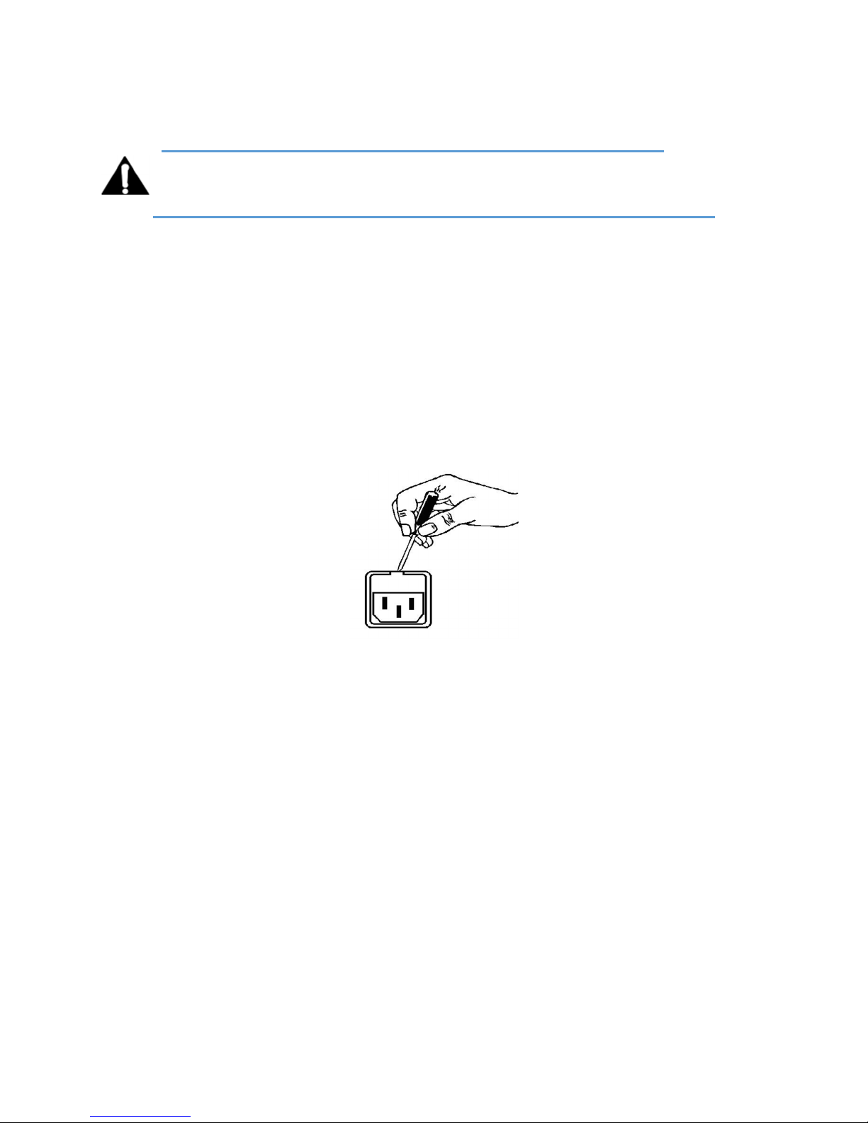
1. Open the fuse compartment door in the AC power input housing with a small flat
blade screwdriver (Figure 1). Carefully pull out the fuse carrier.
L16/1/18039
2. Check that the replacement fuse has the correct rating. The fuse carrier must be
inserted into the compartment carefully. Do not force the carrier into the compartment
or both could be damaged.
3. Snap the fuse compartment door closed.
Internal Fuse
The switching power supply contains a separate fuse. Most fault conditions should be protected
by the main fuse.
If you find it necessary to replace the internal fuse, be certain to replace it with a fuse of the
same type and rating as printed on the switching power supply board.
©2016 LINEAR ACOUSTIC INC. THE TELOS ALLIANCE. ALL RIGHTS RESERVED
Page viii
Page 9

AERO.2000 User Guide July 2016
2.7
2.7 NOTICE
NOTICE
2.72.7
NOTICENOTICE
All versions, claims of compatibility, trademarks, etc., of hardware and software products not
made by Linear Acoustic which are mentioned in this manual or accompanying material are
informational only. Linear Acoustic makes no endorsement of any particular product for any
purpose, nor claims any responsibility for operation or accuracy. We reserve the right to make
improvements or changes in the products described in this manual which may affect the
product specifications, or to revise the manual without notice.
2.8
2.8 UPDATES
UPDATES
2.82.8
UPDATESUPDATES
The operation and features of the AERO.2000 are determined largely by software. From time to
time we may release new versions to add features and fix bugs. Check the Linear Acoustic web
site for the latest information.
2.9
2.9 FEEDBACK
FEEDBACK
2.92.9
FEEDBACKFEEDBACK
We welcome feedback on any aspect of AERO.2000 or this manual. In the past, many good
ideas from users have made their way into software revisions or new products. Please contact
us with your comments.
L16/1/18039
2.10
2.10 SERVICE
2.102.10
You must contact Linear Acoustic before returning any equipment for factory service. We will
need your unit’s serial number, located on the back of the unit. Linear Acoustic will issue a
return authorization number, which must be written on the exterior of your shipping container.
Please do not include cables or accessories unless specifically requested by the Technical
Support Engineer. Be sure to adequately insure your shipment for its replacement value.
Packages without proper authorization may be refused. US customers, please contact Linear
Acoustic Technical Support at +1 (717) 735-3611 and listening through to the end of the
message. All other customers should contact local representative to make arrangements for
service.
2.11
2.11 SUPPORT
2.112.11
SERVICE
SERVICESERVICE
SUPPORT
SUPPORTSUPPORT
You may reach our 24/7 Support team anytime around the clock by calling:
+1 (717) 735-3611 and listening through to the end of the message.
For billing questions or other non-emergency technical questions, call:
+1 (717) 735-3611 between the hours of 9:00 AM to 5:00 PM, USA Eastern time, Monday
through Friday.
Our Fax number: +1-717-735-3612
Technical support is available at [email protected]
All other questions, please email [email protected]
©2016 LINEAR ACOUSTIC INC. THE TELOS ALLIANCE. ALL RIGHTS RESERVED
Page ix
Page 10

AERO.2000 User Guide July 2016
The Linear Acoustic web site has a wealth of information which may be useful for product
selection and support. The URL is www.linearacoustic.com.
2.12
2.12 REGISTER YOUR PRODUCT
2.122.12
Did you know that all Linear Acoustic products come with a 2-Year Warranty? Take a moment
to activate your coverage online under the Support tab at www.linearacoustic.com.
REGISTER YOUR PRODUCT
REGISTER YOUR PRODUCTREGISTER YOUR PRODUCT
L16/1/18039
©2016 LINEAR ACOUSTIC INC. THE TELOS ALLIANCE. ALL RIGHTS RESERVED
Page x
Page 11

AERO.2000 User Guide July 2016
3333 Contents
Contents
ContentsContents
L16/1/18039
1 Warranty Information .............................................................................................................. ii
2 Regulatory Notices and Fusing Information ........................................................................... iv
2.1 FCC .................................................................................................................................... iv
2.2 Canada .............................................................................................................................. iv
2.3 UL ...................................................................................................................................... iv
2.4 UK ...................................................................................................................................... v
2.5 EU ...................................................................................................................................... v
2.6 Fusing Information ......................................................................................................... viii
2.7 NOTICE .............................................................................................................................. ix
2.8 UPDATES ........................................................................................................................... ix
2.9 FEEDBACK ......................................................................................................................... ix
2.10
SERVICE ......................................................................................................................... ix
2.11
SUPPORT ....................................................................................................................... ix
2.12
REGISTER YOUR PRODUCT ............................................................................................ x
4 Introduction to AERO.2000 ..................................................................................................... 1
4.1 Getting Started ................................................................................................................. 2
4.2 Definitions ........................................................................................................................ 3
4.3 Back Panel ........................................................................................................................ 5
4.4 System Block Diagram ...................................................................................................... 7
4.5 Power ............................................................................................................................. 10
5 Front Panel Navigation ......................................................................................................... 11
5.1 Navigation ...................................................................................................................... 11
5.2 Front Panel Menus ......................................................................................................... 12
5.3 Unlock the Front Panel ................................................................................................... 13
5.4 Ethernet Setup ............................................................................................................... 13
5.5 HTTP Setup ..................................................................................................................... 15
5.6 Front Panel Displays ....................................................................................................... 15
5.7 Jump to the IP Remote: NfRemote ................................................................................ 17
5.8 Other Important Setup Parameters ............................................................................... 17
Page 12

AERO.2000 User Guide July 2016
L16/1/18039
5.8.1 Password ................................................................................................................. 17
5.8.2 Reference ................................................................................................................ 18
5.8.3 AES Audio Output Routing ...................................................................................... 18
5.8.4 SDI Audio Output Routing ....................................................................................... 19
5.8.5 Configuring Video Compensation Delay ................................................................. 21
5.8.6 Configuring Audio Delay ......................................................................................... 22
5.9 Front Panel Navigation- Conclusion ............................................................................... 23
6 Using NfRemote .................................................................................................................... 24
6.1 Downloading NfRemote From the AERO.2000 HTTP server .......................................... 24
6.2 Start NfRemote From a Copy on your PC ....................................................................... 25
6.3 Getting Connected ......................................................................................................... 25
6.4 Using NfRemote ............................................................................................................. 27
6.5 Tree and Tabbed Navigation .......................................................................................... 29
6.6 Configuring Meter Displays ............................................................................................ 30
6.7 Configuring Loudness Meters ........................................................................................ 33
6.8 Configuring AERO.2000 I/O ............................................................................................ 34
6.8.1 SDI Embedding ........................................................................................................ 34
6.8.2 Instance 1 Input Sources ......................................................................................... 35
6.8.3 Output Routing ....................................................................................................... 36
6.9 Using the Meters ............................................................................................................ 36
6.10
UPMAX ........................................................................................................................ 39
6.10.1 Enable and Configure UPMAX ................................................................................ 39
6.10.2 UPMAX Operating Modes ....................................................................................... 40
6.10.3 Adjusting the Upmix ............................................................................................... 41
6.11
Loudness Control ........................................................................................................ 42
6.11.1 Loudness Control Guide .......................................................................................... 43
6.12
Factory Presets ........................................................................................................... 44
6.12.1 Fine Arts 5B Gen...................................................................................................... 44
6.12.2 ITU 5B Loudness Lim ............................................................................................... 44
6.12.3 Music 5B HVY .......................................................................................................... 45
6.12.4 MVPD 5B Gen .......................................................................................................... 45
6.12.5 Net 5B Limit ............................................................................................................. 45
©2016 LINEAR ACOUSTIC INC. THE TELOS ALLIANCE. ALL RIGHTS RESERVED
Page xii
Page 13

AERO.2000 User Guide July 2016
L16/1/18039
6.12.6 Protection Limit....................................................................................................... 45
6.12.7 Reference Settings .................................................................................................. 45
6.12.8 Sports 5B GEN ......................................................................................................... 45
6.12.9 TV 4B GEN ............................................................................................................... 45
6.12.10 TV 5B GEN (Default) ............................................................................................ 45
6.12.11 TV 5B HVY ............................................................................................................ 46
6.12.12 TV 5B LIGHT ......................................................................................................... 46
6.12.13 TV 5B LOUD ......................................................................................................... 46
6.13
Making Changes to Presets ........................................................................................ 46
6.14
UPMAX II Local ............................................................................................................ 48
6.15
Nielsen Watermark ..................................................................................................... 49
6.16
NTP Setup ................................................................................................................... 50
6.17
GPI Setup .................................................................................................................... 51
6.18
General Notes About NfRemote ................................................................................ 52
7 Configuration Check List ....................................................................................................... 54
8 Logs and Control Scripts ....................................................................................................... 57
8.1 HTTP Server Access ........................................................................................................ 57
8.2 HTTP List Parameters ..................................................................................................... 58
8.3 Creating a Script ............................................................................................................. 62
8.4 AERO Scheduling ............................................................................................................ 66
8.5 Loudness Logs ................................................................................................................ 68
9 Special Features .................................................................................................................... 73
9.1 SAP (secondary audio program) Handling ..................................................................... 73
9.2 Downmix Outputs .......................................................................................................... 73
9.3 Local Audio Insert/Replace ............................................................................................ 74
9.4 Dolby Insert .................................................................................................................... 75
9.5 Dolby Encoding of Instance 1 SAP using Instance 2 Dolby Encoder .............................. 76
9.6 Auto Replace of Stereo Program by 5.1 Surround Program .......................................... 76
10 Troubleshooting .................................................................................................................... 79
10.1
The unit does not power on ....................................................................................... 80
10.2
Dialogue causes surrounds to pump .......................................................................... 80
10.3
Output audio clicks and pops ..................................................................................... 80
©2016 LINEAR ACOUSTIC INC. THE TELOS ALLIANCE. ALL RIGHTS RESERVED
Page xiii
Page 14

AERO.2000 User Guide July 2016
10.4
Dolby Digital, Dolby Digital Plus or Dolby E output dropouts .................................... 81
10.5
Audio sounds strange ................................................................................................. 81
10.6
Audio issues disappear in bypass ............................................................................... 81
10.7
Audio fixed by re-boot ................................................................................................ 81
10.8
Audio has artifacts ...................................................................................................... 82
L16/1/18039
11 Specifications ........................................................................................................................ 83
11.1
Latency ........................................................................................................................ 84
11.2
Connector Pinouts ...................................................................................................... 85
©2016 LINEAR ACOUSTIC INC. THE TELOS ALLIANCE. ALL RIGHTS RESERVED
Page xiv
Page 15

AERO.2000 User Guide July 2016
4444 Introduction to AERO.2000
Introduction to AERO.2000
Introduction to AERO.2000Introduction to AERO.2000
The Linear Acoustic AERO.2000 Audio Loudness Manager is a state-of-the-art, adaptive,
multiband, broadcast audio loudness controller with one or (optionally) two or three processing
instances, each of which can be specified in a 5.1+2+2, 2+2+2, or 2+2+2+2+2 configuration.
Each processing engine within the configuration can apply loudness control to the incoming
audio content. 5.1 surround processing engines (AMX5.1) can accept either discrete 5.1 audio
or upmix stereo content to 5.1 surround. The two 2-channel DRCs in an AMX5.1 engine can
function as independent stereo processors for other audio programs such as SAP or DVS, or
provide an Lo/Ro or Lt/Rt downmix of the 5.1 output (including automatic replacement of a
downmix in the absence of SAP audio) and, depending upon the specifics of the configuration,
insert local audio such as EAS or local emergency audio.
Professional audio metadata can be applied to the AERO.2000 to minimize processing and
control functions, such as upmixing. AERO.2000 protects itself against loss of incoming
metadata with reversion modes that apply user set reference loudness values. The resulting
audio is clean, consistent, and appropriately dynamic - perfect for transmission to consumers
via Dolby® Digital (AC-3), Dolby Digital Plus (E-AC-3), or any other format.
The AERO.2000’s features include:
L16/1/18039
• Program configurations: any combination of three AMX5.1 (5.1+2+2), AMX2.0 (2+2+2),
or AMX5x2 (2+2+2+2+2) processing engines with support for local input on the last
stereo DRC of each instance.
• HD/SD-SDI audio de-embedding and re-embedding for all eight embedded channel
pairs plus eight pairs of AES-3, unbalanced, I/O.
• AEROMAX® multiband loudness processing which provides ITU-R BS.1770-3 and EBU
R128 compliant audio. AEROMAX includes wideband input AGC plus two additional
wideband AGC’s, two to five bands of multiband AGC and limiting, parametric EQ, lookahead final peak limiting, and selectable multiband source noise reduction.
• ITU-R BS.1770-3 meters for LKFS or EBU R-128 measurement of each output program.
• Selectable independent upmixers for main and local program sources, utilizing the
industry-standard UPMAX®II algorithm and AutoMAX™ detection and automatic
switching between stereo and discrete 5.1 sources.
©2016 LINEAR ACOUSTIC INC. THE TELOS ALLIANCE. ALL RIGHTS RESERVED
Page 1
Page 16

AERO.2000 User Guide July 2016
• Full-time Lt/Rt or Lo/Ro downmix (or stereo output) of main 5.1-surround or main
stereo channel program is selectable on two stereo program outputs.
• SDI video delay.
• Dual, redundant, auto-ranging power supplies.
• Decoding options: Dolby Digital (AC-3), Dolby Digital Plus (E-AC3) and/or Dolby E.
• Encoding options: Dolby Digital, Dolby Digital Plus (E-AC3 and/or Dolby E.
• GPI and Ethernet control.
• NfRemote IP-based, full-function remote control for configuration and monitoring.
• Nielsen® Watermark encoding option for all program outputs.
• Internal logging of loudness measurement data, True Peak, and channel configuration
(acmod) and Dialnorm status for each program output.
L16/1/18039
4.1
4.1 Getting Started
Getting Started
4.14.1
Getting StartedGetting Started
This user guide is intended to be read while in front of a running AERO.2000 unit. It is most
helpful if the source(s) that will be used is actually connected to the AERO.2000. Doing this
provides feedback to the user, via the meters and IP audio monitoring, about the configuration
changes being made.
To make learning your way around the AERO.2000 as useful and rewarding as possible there is
some information that you should have at hand:
• The IP address and subnet mask to be assigned to the AERO.2000.
• Any gateway and DNS information for the network to which it will be attached.
• NTP server address(s)
• The IP address of the PC that will be used to connect to the AERO.2000.
• Knowledge of where the audio program(s) are embedded in the SDI source.
Knowledge of where the loudness controlled audio program(s) need to be embedded in
the SDI output.
Having this information will allow you to configure the unit for use as you learn to navigate the
AERO.2000 using both the front panel screen and controls and NfRemote.
©2016 LINEAR ACOUSTIC INC. THE TELOS ALLIANCE. ALL RIGHTS RESERVED
Page 2
Page 17

AERO.2000 User Guide July 2016
Even if you are already a user of a Linear Acoustic loudness controllers you may want to read
through both Section 5 and Section 6. These sections cover front panel navigation and
NfRemote. Both contain important information about the configuration of the latest software
and firmware versions of this product.
Note!
L16/1/18039
All newer software versions of AERO.2000 REQUIRE A PASSWORD to operate.
Saving an empty password field (or restoring a configuration that does not have
a password) will prevent any further access to the unit. The unit must be
returned to the factory to restore a password. If you do not already know this,
then please, read sections 5.2 and 5.3 carefully.
Even experienced users should look at Section 7 Configuration Check List. This contains a brief
description of all of the items that need to be configured for typical use.
Section 9 Special Features, describes some of the special processing features that are part of
the AERO.2000 and where to find them.
If you are a new user, please register on the Linear Acoustic website at
www.linearacoustic.com. Click the Log In button and follow the instructions there. One benefit
of registering is that there are Application Notes available on the AERO.2000 page. These
provide specific configuration details about how to configure AERO.2000 for specific needs such
as EAS insertion, local emergency audio insertion, and local program insertion. Software
updates and user manuals can also be found on the product pages.
4.2
4.2 Definitions
Definitions
4.24.2
DefinitionsDefinitions
An AMX Instance, or simply “instance”, refers to a virtual block of processing capability. The
AERO.2000 comes loaded with one AMX5.1 Instance and, optionally, can have two additional
Instances;, AMX5.1, AMX2.0, or AMX5x2 can be added at the time of purchase or in the field at
a later time.
• An AMX5.1 Instance is capable of processing a surround program and two stereo
programs. This is referred to as 5.1 + 2 + 2 (or in some references as 5.1 + 2 + Local)
• An AMX2.0 Instance is capable of processing three stereo programs. One source can be
5.1 or mixed 5.1 and stereo. The 5.1 source will be downmixed. AMX2.0 is also referred
to as 2 + 2 + 2 (or in some references as 2 + 2 + Local)
©2016 LINEAR ACOUSTIC INC. THE TELOS ALLIANCE. ALL RIGHTS RESERVED
Page 3
Page 18

AERO.2000 User Guide July 2016
L16/1/18039
• An AMX5x2 Instance is capable of processing five stereo programs. One source can be
5.1 or mixed 5.1 and stereo. The 5.1 source will be downmixed. AMX5x3 is also referred
to as 2+2+2+2+2.
In addition to multiple independent loudness control processors (called DRC1, DRC2, or
DRCLocal) an Instance has many other processing functions. These include:
• Two UPMAX II upmixers, one for main program and one for local insert. (In AMX5.1
instances only)
• Automatic and seamless switching between surround and upmixing of stereo inputs
(AutoMAX)
• Downmixing (Lo/Ro or Lt/Rt)
• Creation of dual channel mono from one channel of an input pair (for SAP, DVS and local
emergency audio)
• Automatic replacement of SAP (or any stereo/mono source) with a downmix of the main
channel
• SDI source pair shuffling and embedding of AES digital audio inputs into the SDI output
• Local program insertion
• EAS or local emergency audio insertion
A DRC is the Dynamic Range Control portion of an Instance which provides loudness control.
Each Instance has 3 or more DRC engines; DRC 1, DRC 2and DRC Local are the minimum
number for any instance. In the AERO.2000 interface, DRC 1, DRC 2 and DRC Local are
sometimes referred to as DRC - Program 1, DRC - Program 2 and DRC - Local. An AMX5x2
engine has five DRC engines; DRC 1, DRC2, DRC 3, DRC4 and DRC5 (or DRC Local
DRC Local (or just “Local”) is the DRC with the capability to replace the output of DRC 1, DRC2,
or or both DRC 1 and DRC 2 programs, with locally inserted audio. The replacement can be
triggered by GPI, by IP command or manually.
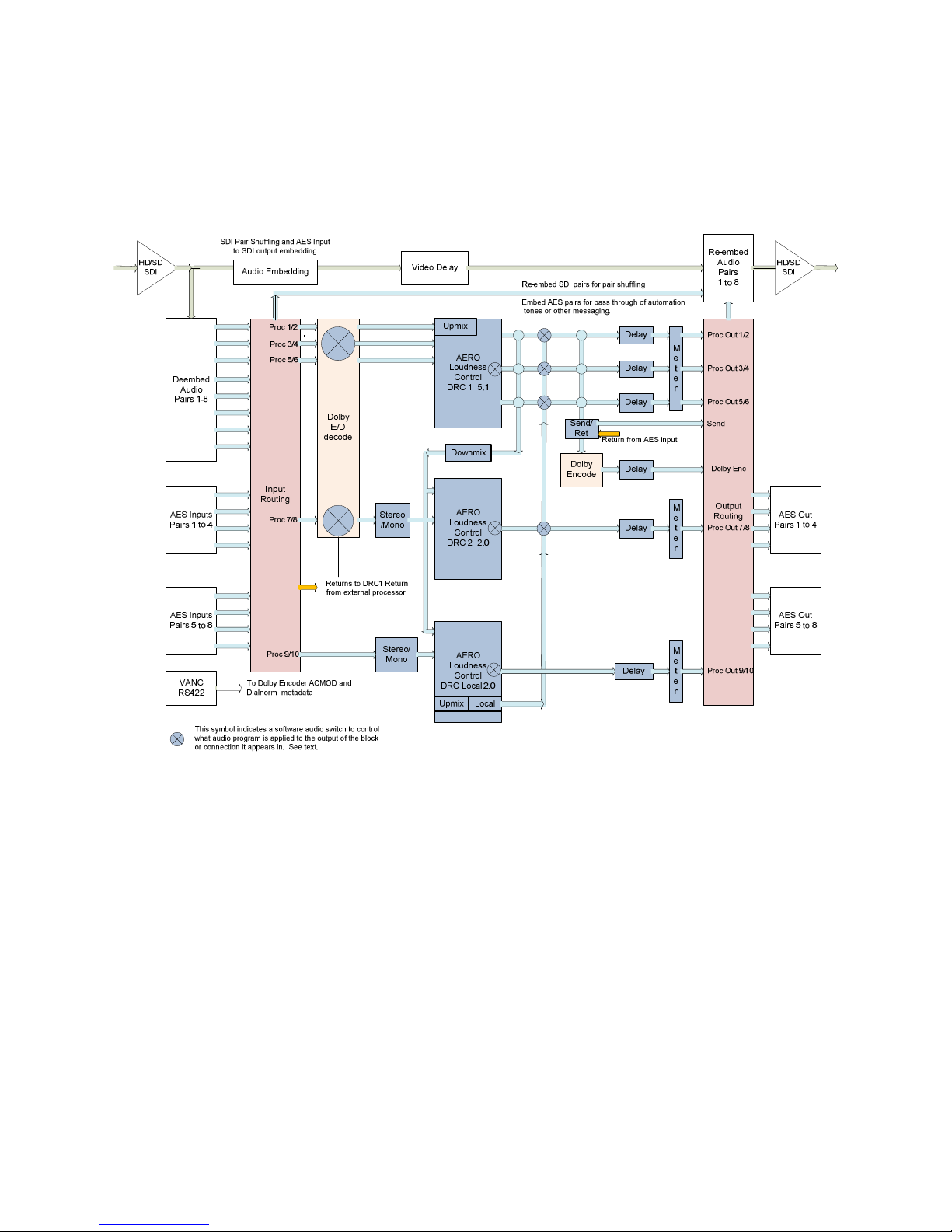
Please see the block diagrams of the 5.1 and 2.0 instances for more information about signal
flow.
DARS is “digital audio reference signal”. This is an AES digital audio signal and can be silent or
contain audio. A timing reference is derived from the AES signal’s timing. This is NOT word
clock.
AES is sometimes used in the manual as an abbreviation for an AES-3 digital audio connection.
This rest of this Section includes:
• A description of back panel connectors
• System block diagrams
• A note on powering the AERO.2000
©2016 LINEAR ACOUSTIC INC. THE TELOS ALLIANCE. ALL RIGHTS RESERVED
Page 4
Page 19
AERO.2000 User Guide July 2016
See Connector Pinouts, at the end of the manual, for AES and analog connector, Metadata, and
GPI pinout tables.
4.3
4.3 Back Panel
Back Panel
4.34.3
Back PanelBack Panel
L16/1/18039
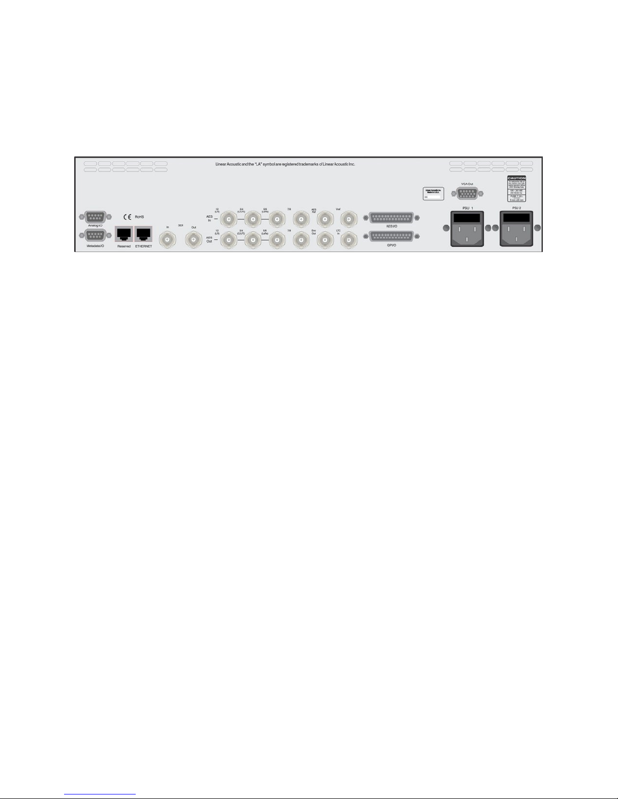
Figure 4-1 AERO.2000 back panel
Figure 5-1 shows the AERO.2000 back panel. Its connector functions are described below from
left to right:
• Analog I/O (DB9) – One stereo +4 dBu I/O
• Metadata I/O (DB9) – RS-485 metadata (no crossover cable required)
• Reserved (RJ45) – Reserved for future use (not connected internally)
• ETHERNET (RJ45) – Auto-sense 100/1000 BASE-T, requires connection to stable network
• SDI I/O (dual BNC) – Auto-sensing SD/HD, supports 16 audio channels, VANC metadata,
and has internal compensating video delay
• Main AES I/O (BNC) – 8 AES digital audio pairs (Channels 1 – 8) I/O
• AES Ref (BNC) – Apply 48 kHz DARS (Digital Audio Ref Signal), or any AES signal, but not
video. Use only if SDI embedding is disabled.
• ENC Out (BNC) – Encoder output, fed in parallel with AES digital audio output pair 15/16
• Vref (BNC) – Video reference input (supported in v 3.16.02 and later)
• LTC In (BNC) – LTC timecode input (not currently supported)
• AES I/O (DB25) – 4 AES audio pairs (channels 9-16), unbalanced (pinout below)
• GPI/O (DB25) – Eight parallel inputs, 5-V TTL levels, active low
• VGA Out (HD-DB15) – VGA (640 x 480) video output
• PSU1/PSU2 – AC power inlets
©2016 LINEAR ACOUSTIC INC. THE TELOS ALLIANCE. ALL RIGHTS RESERVED
Page 5
Page 20

AERO.2000 User Guide July 2016
Note!
All BNC inputs are 75-Ω internally terminated.
L16/1/18039
©2016 LINEAR ACOUSTIC INC. THE TELOS ALLIANCE. ALL RIGHTS RESERVED
Page 6
Page 21
AERO.2000 User Guide July 2016
4.4
4.4 System Block Diagram
System Block Diagram
4.44.4
System Block DiagramSystem Block Diagram
Figure 4-2 shows AERO.2000’s physical I/O on the left and right sides, respectively, and AMX5.1
processing (5.1 + 2 + 2).
L16/1/18039
Figure 4-2 AERO.2000 block diagram AMX5.1 (5.1 + 2 + 2)
©2016 LINEAR ACOUSTIC INC. THE TELOS ALLIANCE. ALL RIGHTS RESERVED
Page 7
Page 22
AERO.2000 User Guide July 2016
L16/1/18039
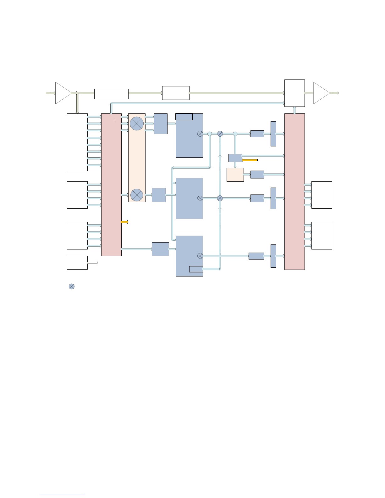
Figure 4-3 shows a detailed view of AMX2.0 processing (2+2+2).
SDI Pair Shuffling and AES Input
HD/SD
SDI
Deembed
Audio
Pairs 1-8
AES Inputs
Pairs 1 to 4
to SDI output embedding
Audio Embedding
Proc 1/2
Proc 3/4
Proc 5/6
Input
Routing
Proc 7/8
Dolby
E/D
decode
Down-
mix
Stereo
/Mono
Video Delay
Upmix
AERO
Loudness
Control
DRC 1 2.0
AERO
Loudness
Control
DRC 2 2.0
Re-embed SDI pairs for pair shuffling
Embed AES pairs for pass through of automation
tones or other messaging.
Send/
Ret
Dolby
Encode
Delay
Return from AES input
Delay
Delay
Re-embed
Audio
Pairs
1 to 8
M
e
Proc Out 1/2
t
e
r
Send
Dolby Enc
Output
M
Routing
e
Proc Out 7/8
t
e
r
HD/SD
SDI
AES Out
Pairs 1 to 4
AES Inputs
Pairs 5 to 8
Proc 9/10
VANC
RS422
This symbol indicates a software audio switch to control
what audio program is applied to the output of the block
or connection it appears in. See text.
To Dolby Encoder ACMOD and
Dialnorm metadata
Figure 4-3 Instance 2 AMX2.0 (2 + 2 + 2)
Returns to DRC1 Return
from external processor
Stereo/
Mono
AERO
Loudness
Control
DRC Local 2.0
Local
AES Out
Pairs 5 to 8
M
e
Delay
t
e
r
Proc Out 9/10
©2016 LINEAR ACOUSTIC INC. THE TELOS ALLIANCE. ALL RIGHTS RESERVED
Page 8
Page 23
AERO.2000 User Guide July 2016
L16/1/18039
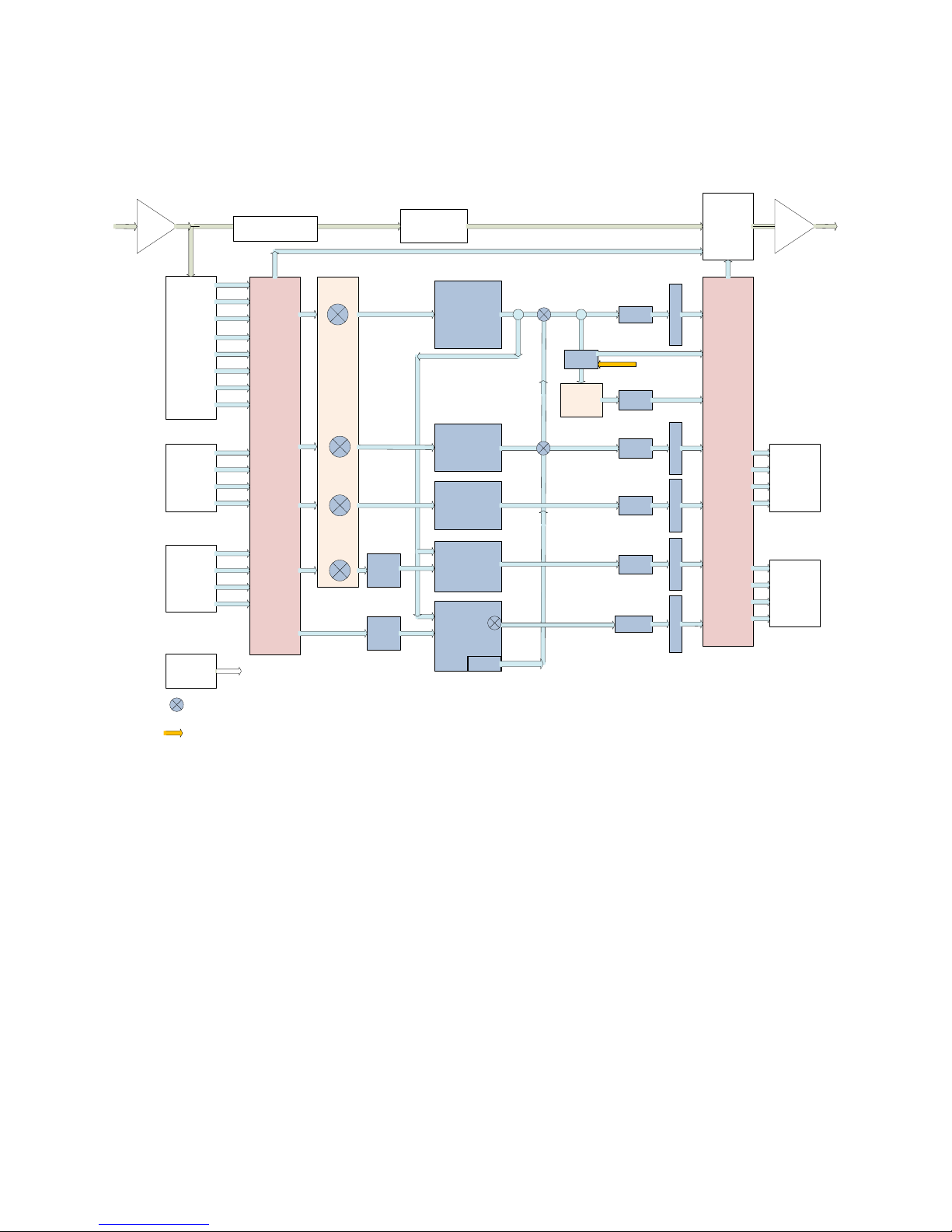
Figure 4-4 shows a detailed view of AMX5x2 processing (2+2+2+2+2).
HD/SD
SDI
SDI Pair Shuffling
Audio Embedding
Proc 1/2
Deembed
Audio
Pairs 1-8
Proc 3/4
Input
AES Inputs
Pairs 1 to 4
AES Inputs
Pairs 5 to 8
VANC
RS422
This symbol indicates a software audio switch to control
what audio program is applied to the output of the block
or connection it appears in. See text.
Returns to DRC1 Return
from external processor
Routing
Proc 5/6
Proc 7/8
Proc 9/10
To Dolby Encoder ACMOD and
Dialnorm metadata
Dolby E
Decoding
Stereo
/Mono
Stereo
/Mono
Video Delay
DRC Local 2.0
AERO
Loudness
Control
DRC 1 2.0
AERO
Loudness
Control
DRC 2 2.0
AERO
Loudness
Control
DRC 2 2.0
AERO
Loudness
Control
DRC 2 2.0
AERO
Loudness
Control
Local
Re-embed SDI pairs for pair shuffling
Embed AES pairs for pass through of automation
tones or other messaging.
Delay
Send/
Ret
Return from AES input
Dolby
Encode
Delay
Delay
Delay
Delay
Delay
M
e
e
M
e
e
M
e
e
M
e
e
M
e
e
t
r
t
r
t
r
t
r
t
r
Re-embed
Audio
Pairs
1 to 8
Proc Out 1/2
Send
Dolby Enc
Out
Proc Out 3/4
Proc Out 5/6
Proc Out 7/8
Proc Out 9/10
HD/SD
SDI
AES Out
Pairs 1 to 4
AES Out
Pairs 5 to 8
Figure 4-4 Instance AMX5x2 (2 + 2 + 2 + 2 + 2)
©2016 LINEAR ACOUSTIC INC. THE TELOS ALLIANCE. ALL RIGHTS RESERVED
Page 9
Page 24

AERO.2000 User Guide July 2016
4.5
4.5 Power
Power
4.54.5
PowerPower
The AERO.2000 is equipped with two power supplies (dual redundant internal PSUs). Always
connect BOTH power inlets to clean AC power sources, ideally from separate AC power feeds.
Remember, this is primarily to protect you against unreliable power sources and not from
problems with AERO.2000’s power supplies. We strongly recommend using an uninterruptible
power supply (UPS) on at least one if not both of the AC power feeds.
Apply AC power to power on the AERO.2000; there is no power switch. The blue light behind
the Linear Acoustic logo illuminates, the LCD screen shows the Linear Acoustic logo, and fans
turn on. When the menu appears on the LCD screen, startup is complete and the unit is ready
to use. This process may take up to two minutes.
To power off, just remove both AC power cords from the unit.
L16/1/18039
©2016 LINEAR ACOUSTIC INC. THE TELOS ALLIANCE. ALL RIGHTS RESERVED
Page 10
Page 25
AERO.2000 User Guide July 2016
5555
Front Panel Navigation
Front Panel Navigation
Front Panel NavigationFront Panel Navigation
5.1
5.1 Navigation
Navigation
5.15.1
NavigationNavigation
The AERO.2000 has both front panel control and a full function IP remote control. We think
that the IP remote is both faster and easier to use but familiarity with the front panel control
will allow users to unlock the front panel and make changes without a network connection or
PC. Once the logic of the front panel menus is understood a user can make changes to any of
the AERO.2000 parameters right from the front panel. Following are a few lessons on how to
use the front panel controls.
The lessons follow the steps needed to put the units into operation when it is received.
Following the steps below will get you started!
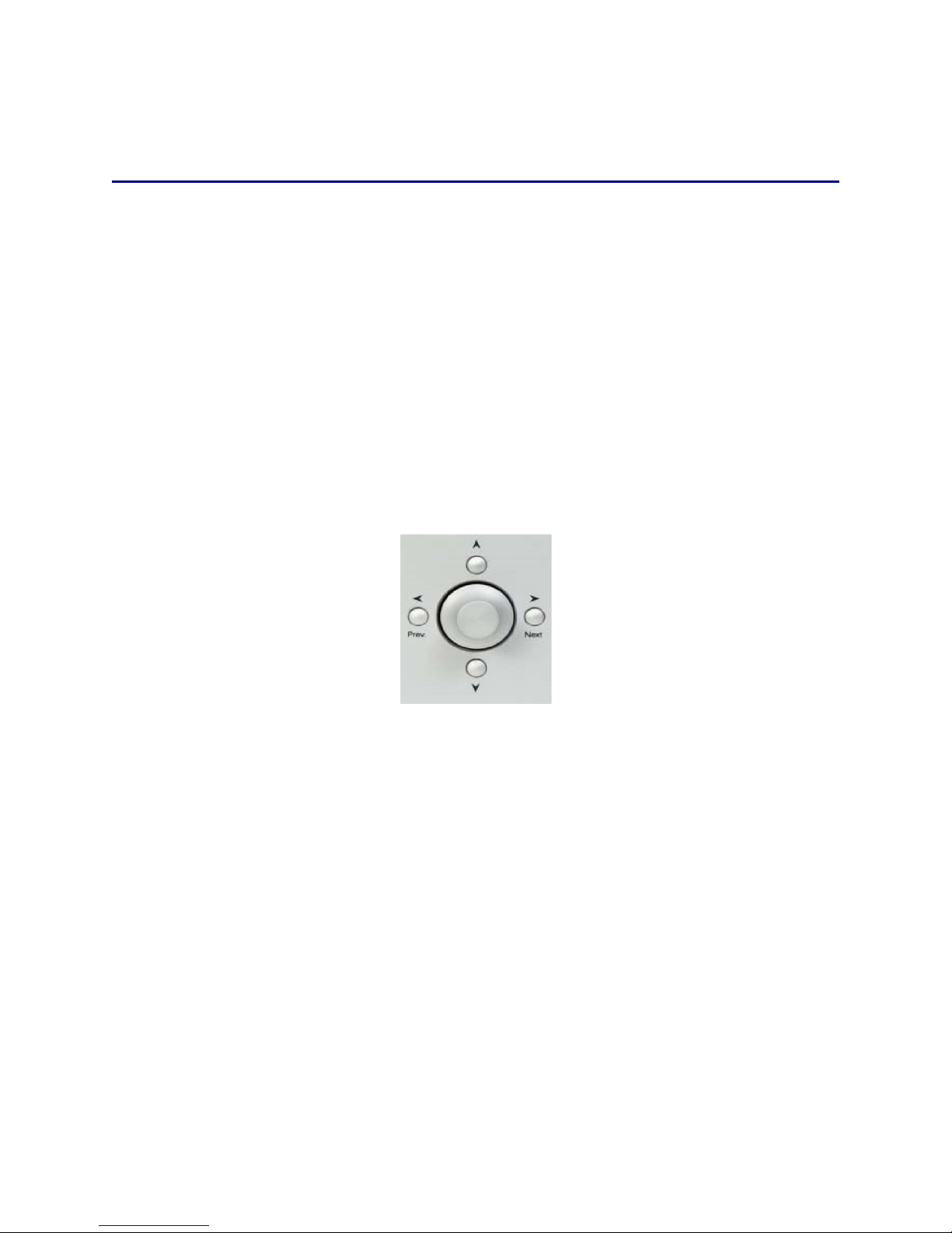
The right, left, up, and down arrow keys and the rotary encoder navigate AERO.2000’s menu
system. See Figure 5-1.
L16/1/18039
Figure 5-1 Menu navigation keys
•
►
Next Takes you into the selected menu; same as Enter (Right in the text)
•
◄
Prev. Takes you back the same path; same as Back or Esc (Left in the text)
• ▲▼ Scrolls through screen parameters (Up and Down in the text)
The rotary encoder adjusts the selected parameter. (Rotary in the text)
In describing the use of the front panel controls phrases like: “Use the Up/Down arrows to
highlight System” will be used. This will be done for the first few examples to help those
unfamiliar with the menus and front panel controls. Step by step instructions that walk the
user through making a change to a setting are provided.
After the first few examples the instructions will be shortened to “select” System and this has
the same meaning as: Use the Up/Down arrow keys to highlight (put the yellow border around)
the menu selection ‘System’. An instruction to select System will almost always be followed by
©2016 LINEAR ACOUSTIC INC. THE TELOS ALLIANCE. ALL RIGHTS RESERVED
Page 11
Page 26
AERO.2000 User Guide July 2016
press Right which will then open the selected menu. These step by step instructions will be
shortened, later in the manual, to:
• Instance 1 > DRC Program 1 > Load Preset > Load a Preset > TV 5B Light.
This means Select Instance 1, press Right, then select DRC Program 1 and Press Right, then
select Load Preset and press Right, etc. (It is assumed that the starting point is always the top
level, i.e. the main menu.). This string of menu titles is the ‘breadcrumb’ style that is seen at
the top of the menu window. This is described in section 6.2.
5.2
5.2 Front Panel
Front Panel Menus
5.25.2
Front Panel Front Panel
AERO.2000’s menus are hierarchical, and follow logical signal processing flows. When a
parameter is changed from its stored value it is displayed in yellow until the change is saved.
When it is saved, it returns to white.
AERO.2000 employs “breadcrumbs” in the menus so you will always know where you are in the
menu hierarchy. The top of each menu displays the breadcrumbs to the current menu position.
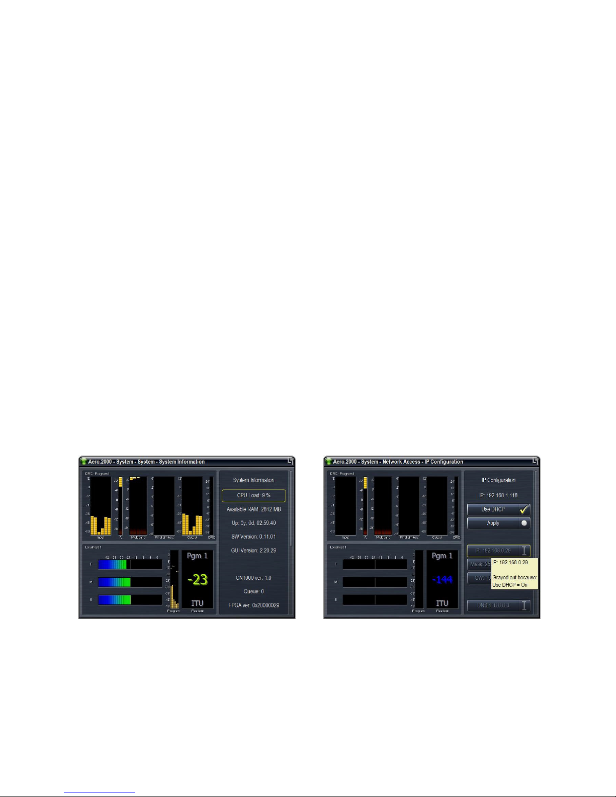
For example, Figure 5-2 shows the menu position as AERO.2000 > System > System > System
Information.
The menu also displays pop up tips and hints to explain a function or why it is inactive. For
example, Figure 5-2 (right) shows why the IP Address field is grayed out and inactive. You will
see this if you navigate to the grayed out selection and press the Right arrow key.
Menus
MenusMenus
L16/1/18039
Figure 5-2 Left: menu path at top; Right: yellow popup hint
©2016 LINEAR ACOUSTIC INC. THE TELOS ALLIANCE. ALL RIGHTS RESERVED
Page 12
Page 27

AERO.2000 User Guide July 2016
5.3
5.3 Unlock
Unlock the Front Panel
5.35.3
Unlock Unlock
When the unit is powered up you will see two meters on the left and the password lock screen
on the right. There is a blank password entry field at the top.
1. If it is not highlighted with a yellow border use the Up/Down arrows to highlight the
empty password field and then press the Right arrow. An ASCII entry screen will appear.
2. Use the Rotary to highlight the numeric keyboard selection [123] and press the Right
arrow
3. Use the Rotary to highlight each character in the password and press the Right arrow
after each selection. The factory password is 1234. The password will appear at the top.
4.
The AERO.2000 MUST have a password. Erasing the password and saving
the Front Panel
the Front Panelthe Front Panel
L16/1/18039
will require the unit to be sent back to the factory to be unlocked! If you
change the password keep your password in a safe place.
5. Use the Rotary to highlight OK and press the Right arrow.
6. The screen is now back on the password screen. Use the Down arrow to highlight
Unlock and press Right arrow. The main menu screen is now visible.
7. Use Up/Down arrows to highlight Display Options at the bottom of the main menu and
press Right arrow
8. Use Up/Down arrows to highlight the Menu Options selection at the bottom of this
menu and press Right arrow
9. In this menu you can use the Rotary to, maximize the size of the menu area and the text
on the screen. This will make navigating the menus easier.
5.4
5.4
Ethernet Setup
5.45.4
The Ethernet connection, like a reference signal, must be stable and always present. Audio
glitches may be heard on-air if Ethernet is interrupted. Although initially configured for DHCP
(auto-IP address), DHCP can be disabled and a static IP addresses can be entered. We
recommend a static IP so that NfRemote and any PCs that need to access configuration,
metering, control, or logs will always find the AERO.2000 at the same IP address.
Ethernet Setup
Ethernet SetupEthernet Setup
To enter a static IP address:
1. Press Left arrow several times to navigate back to the AERO.2000 main menu.
©2016 LINEAR ACOUSTIC INC. THE TELOS ALLIANCE. ALL RIGHTS RESERVED
Page 13
Page 28
AERO.2000 User Guide July 2016
L16/1/18039
2. Use Up/Down arrow keys to highlight System and press Right Arrow
3. On System screen use Up/Down arrows to highlight Network Access and press Right
arrow.
4. Use Up/Down arrows to highlight IP Configuration and press Right arrow.
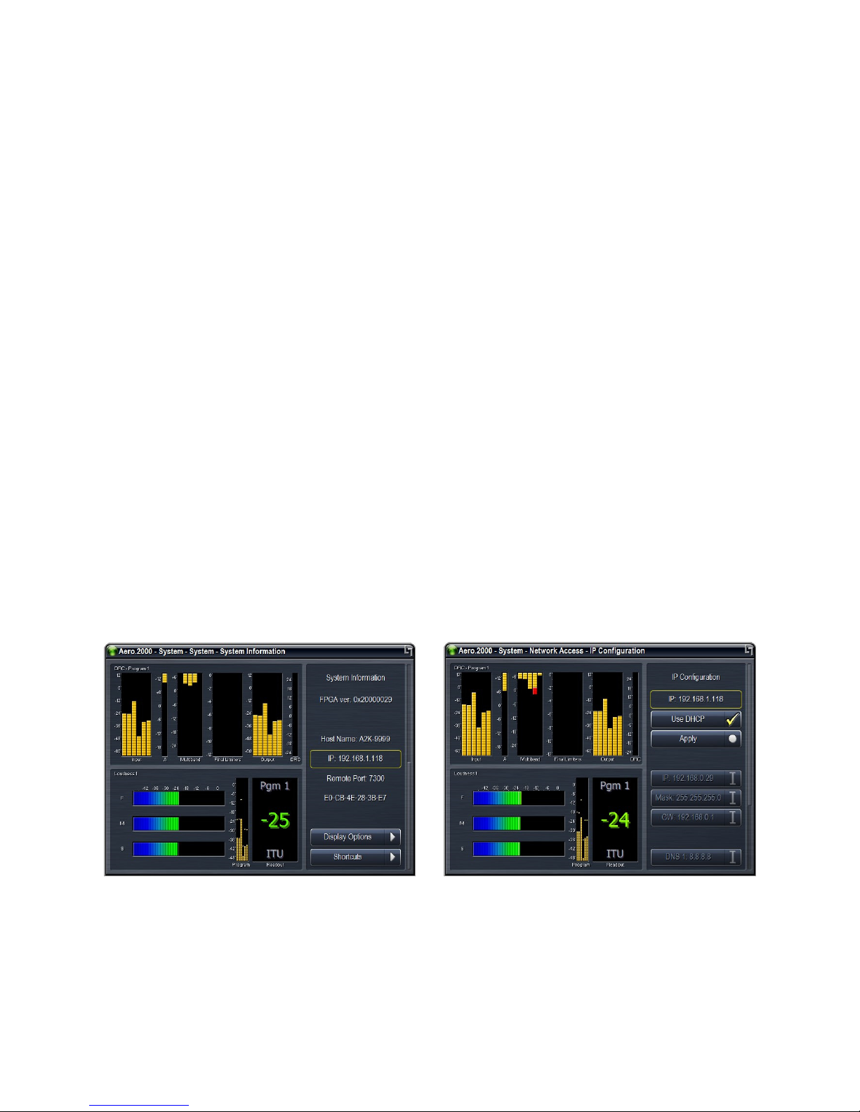
5. Use Up/Down arrows to highlight Use DHCP and the press Right arrow to remove check
mark. See Figure 5-3.
6. Use Up/Down arrows to highlight IP and press Right arrow. The alpha numeric entry
appears. Use the Rotary to select the numeric keyboard [123] and press Right.
7. Use the Rotary to select each numeral and decimal point in the IP address you want to
assign to the AERO.2000. Press Right after each entry until the IP address is entered.
8. Use Rotary to highlight OK and press Right.
9. To exit the alpha numeric entry window at any time, without saving changes, use Rotary
to highlight Abort and press Right arrow.
10. Repeat the IP address setting process to enter the subnet mask, gateway, and DNS
addresses. You can also enter the location of the unit (a room or rack ID for instance).
11. When all the entries are made use Up/Down arrows to highlight Apply and press Right
Arrow.
Figure 5-3 Left: IP address, remote port, and MAC address; Right: reconfiguring IP settings
©2016 LINEAR ACOUSTIC INC. THE TELOS ALLIANCE. ALL RIGHTS RESERVED
Page 14
Page 29

AERO.2000 User Guide July 2016
5.5
5.5 HTTP Setup
HTTP Setup
5.55.5
HTTP SetupHTTP Setup
The AERO.2000 has a built-in HTTP server. Logs of LKFS (LUFS) readings can be accessed
through the HTTP server. IP commands, to control the unit remotely, and scripting functions
(Section 8) are found here as well as a copy of the latest Nf Remote application.
Only computers that have their IP addresses in the HTTP white list, found in HTTP Access, can
access the unit’s HTTP server. We recommend that an IP address, in the same subnet as the
AERO.2000 IP address, is immediately entered in the white list and is also stored in a safe place.
A computer can be connected directly to the unit’s Ethernet port using an ordinary Ethernet
cable. By setting the computer’s IP address and subnet mask to the same IP and subnet mask
stored in the white list the computer can access the AERO.2000’s HTTP server. This access can
even allow you to recover from a lost password without returning the unit to the factory!
From the AERO.2000 main menu use Up/Down arrows to highlight System and press Right
arrow.
Use Up/Down arrows to highlight Network access and press Right arrow.
Use Up/Down arrows to highlight HTTP Access and press Right arrow.
Use Up/Down arrows to highlight IP 1 and press Right arrow. The alpha numeric entry opens.
Using the same process used to set the IP address (above) set a white list IP address and subnet
mask for your PC/laptop.
An example of a valid entry is 192.168.1.200/255.255.255.0 . The subnet and subnet mask
must be the same as the AERO.2000 IP address assignment but must NOT be the same address.
The addresses of any PCs that will access the logs, control the AERO.2000 using commands over
IP, or is permitted to download the NfRemote software can be entered in the white list up to a
total of 8 addresses. Wild cards can also be used to allow an entire subnet access. Example:
192.168.1.*
L16/1/18039
5.6
5.6 Front Panel Displays
Front Panel Displays
5.65.6
Front Panel Displays Front Panel Displays
The front panel display can be customized, and can contain up to six meters of the same or
different types. The display can also be set to “Meters Only” mode so the menus are
temporarily hidden. Of course, display resolution may limit the number of active front panel
meters, but all six will look fine when displayed on a monitor using the AERO.2000 VGA output.
This is found on the rear panel. To setup meters use the Left arrow to navigate to the
AERO.2000 main menu.
©2016 LINEAR ACOUSTIC INC. THE TELOS ALLIANCE. ALL RIGHTS RESERVED
Page 15
Page 30

AERO.2000 User Guide July 2016
L16/1/18039
1. Select Display Options and press Right
2. Select Memory Slot 1 and press Right
3. Use Up/Down arrows to highlight a memory slot and press Right. A check mark will
appear next to your selection.
4. Press Left and then Down to highlight meter 1.
5. Press Right and use Up/Down arrows to select a meter type.
6. The first selection is a choice of the program output to monitor. Any of the three DRCs
can be chosen, or metering of the unit’s I/O that is Common to all DRCs, or Off.
7. Press Right to see the selections and select Program 1. A check mark will appear. Press
Left to exit.
8. Use Down to select what to meter for Program 1. Press Right to see the choices. Use
Up/Down to select DRC-Program 1. A check mark will appear. Press Left to exit.
9. Press Left again to return to the meter selection screen.
10. Select meter 2 and Right to select a source. Select Program 1, and press Right. Use
Up/Down to select Program 1. Left to exit.
11. Use Down arrow to select a meter type, Right to see selections. Use Down arrow to
highlight LM (loudness meter) Program 1. The Right arrow to select Program 1, and Left
arrow to exit.
12. Use Up/Down arrows and highlight meter 3. Right arrow to enter the meter selection.
13. Use Down arrow to highlight Off. Press Right arrow to select and then Left Arrow to
exit.
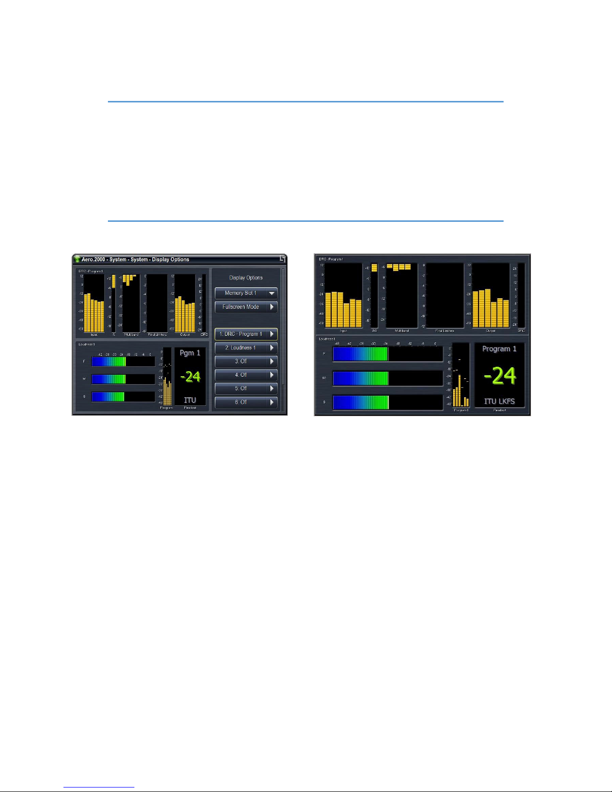
14. Repeat steps 12 and 13 for meters 4, 5, and 6. See Figure 5-4 Left side for the result.
15. Use Up/Down keys to highlight Fullscreen Mode and press Right. See figure 5-4 right
side.
16. Press Left to exit full screen mode.
©2016 LINEAR ACOUSTIC INC. THE TELOS ALLIANCE. ALL RIGHTS RESERVED
Page 16
Page 31
AERO.2000 User Guide July 2016
Note!
If two Instances are installed you must first select Instance 1, press right to enter
the Instance 1 menu, then Left to exit the menu. Now set up meters for Instance
1 from the AERO.2000 main menu. Next, select Instance 2, enter the Instance 2
menu, exit the menu and then setup meters for Instance 2. Once set up the
correct meters for each instance will appear when you enter the menu for each
Instance. When you leave an Instance menu the meters remain active for that
Instance until a different Instance menu is entered.
L16/1/18039
Figure 5-4 Display and meter setup options
5.7
5.7 Jump to
Jump to the IP Remote:
5.75.7
Jump to Jump to
You can continue to configure the AERO.2000 using front panel navigation by continuing with
this section. Or, you can begin working with the IP remote application, NfRemote. We think
that all users will appreciate the speed and ease of using the NfRemote application. Skip to
Section 6 to configure NfRemote and use it to complete the AERO.2000 setup.
5.8
5.8 Other
5.85.8
5.8.1
5.8.1 Password
5.8.15.8.1
A password must ALWAYS be set in the AERO.2000. The factory set password is “1234”. If you
choose to change the password keep it in a safe place. If the password is lost or removed the
unit must be sent back to the factory to regain control of the unit.
the IP Remote: NfRemote
the IP Remote: the IP Remote:
Other Important Setup Parameters
Other Other
Password
PasswordPassword
Important Setup Parameters
Important Setup ParametersImportant Setup Parameters
NfRemote
NfRemoteNfRemote
©2016 LINEAR ACOUSTIC INC. THE TELOS ALLIANCE. ALL RIGHTS RESERVED
Page 17
Page 32

AERO.2000 User Guide July 2016
To change the password:
1. Press Left arrow several times to return to main menu.
2. Select System and press Right.
3. Select Network Access and press Right
4. Select Password and press Right
5. Select Password **** and press Right
6. Use the alpha numeric pad to enter a new password. Use rotary to select OK and press
right to save.
Make sure you save your new password somewhere safe!!
5.8.2
5.8.2 Reference
5.8.25.8.2
The AERO.2000 can be referenced to:
Reference
ReferenceReference
L16/1/18039
• AES DARS (or any AES signal applied to the Ref In connector);
• AES In 1
• SDI
• Internal 48 kHz (standalone use only).
NOTE!
AES output routing is straight forward. Each of the 8 AES digital audio outputs can be assigned
to carry any of the AERO.2000 processed outputs. The processed outputs for a 5.1 Instance
are:
If SDI embedding is enabled, clock reference will be forced to SDI automatically. If
SDI embedding is Off then a valid reference selection must be made.
5.8.3
5.8.3 AES
5.8.35.8.3
AES Audio Output Routing
Audio Output Routing
AES AES
Audio Output RoutingAudio Output Routing
• Off
• Instance 1 Processed 1/2
• Instance 1 Processed 3/4
©2016 LINEAR ACOUSTIC INC. THE TELOS ALLIANCE. ALL RIGHTS RESERVED
Page 18
Page 33

AERO.2000 User Guide July 2016
• Instance 1 Processed 5/6
• Instance 1 Processed 7/8
• Instance 1 Processed 9/10
• Instance 1 DOLBY DIGITAL PLUS Out
If there is a second Instance is installed then these 6 selections are also in the drop down list.
If Instance 2 is a stereo Instance then the selections are:
• Off
• Instance 2 Processed 1/2
• Instance 2 Processed 7/8
• Instance 2 Processed 9/10
L16/1/18039
• Instance 2 DOLBY DIGITAL PLUS Out
The Dolby encoder input is the output of the first DRC in an Instance.
To configure AES outputs from the front panel:
1. Press Left several times until the AERO.2000 main menu is reached.
2. Select Output Routing and press Right.
3. Select AES/SDI Outputs and press Right
4. Select AES Outputs and press Right
5. Select any AES output pair (pair 1/2 to pair 15/16) and press Right.
6. Select any of the Instance(s) processed outputs and press Right to enable the selection.
7. Repeat to route processed audio to any, or all, of the AES outputs or choose Off to mute
any AES output.
5.8.4
5.8.4 SDI Audio Output Routing
5.8.45.8.4
SDI Audio Output Routing
SDI Audio Output RoutingSDI Audio Output Routing
Routing signals to the embedded SDI audio outputs is slightly more complex because there are
many more choices for the audio source:
©2016 LINEAR ACOUSTIC INC. THE TELOS ALLIANCE. ALL RIGHTS RESERVED
Page 19
Page 34
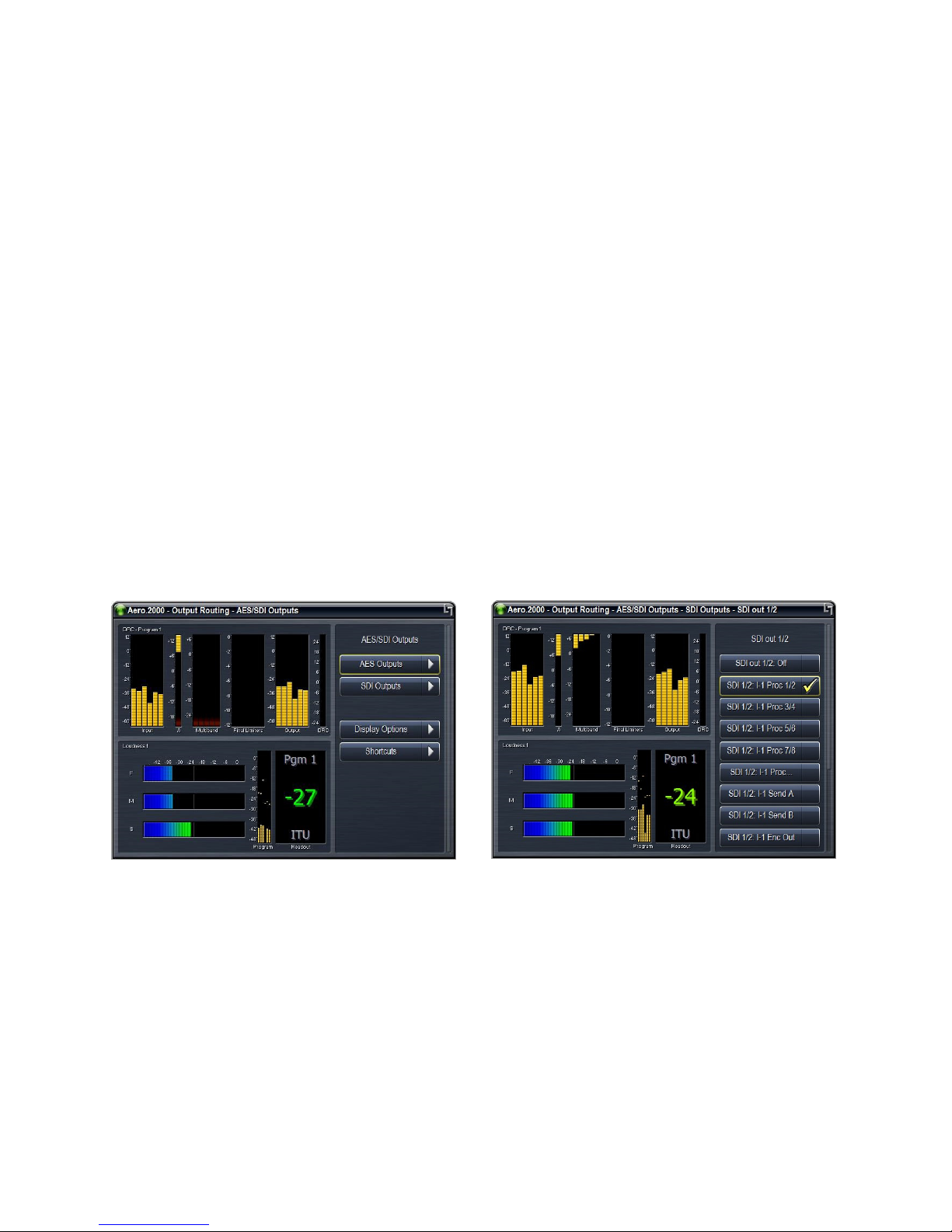
AERO.2000 User Guide July 2016
L16/1/18039
• If SDI embedding is NOT enabled then all of the SDI audio channels in the SDI source are
passed to the SDI output.
• The de-embedder is always active so any of the SDI embedded audio pairs can be
processed and the audio, including Dolby encoded audio, can be sent to any of the AES
digital audio outputs.
• If SDI embedding is enabled then any of the following signals can be routed to any SDI
embedded output pair.
o Any SDI embedded source pair can be routed to any SDI embedded output pair.
We call this audio (pair) shuffling.
o Any AES digital audio input pair can be routed to any SDI embedded output pair.
o Any of the processed output pairs (listed in 5.8.3 above) can be routed to any SDI
embedded output pair.
o If a processed pair is chosen in the SDI Embedding menu then the specific
processed output is chosen in the Output Routing > AES/SDI Outputs > SDI
Outputs menu. See Figure 5-4.
Figure 5-4 Left: main AES outputs (BNC and DB25) and SDI outputs; Right: SDI output setup
SDI output routing is set in two different menus when SDI embedding is Enabled. Starting from
the main menu:
System > I/O Setup > SDI Embedding > SDI Embed.
If SDI embed does not have a check-mark then the SDI embedded inputs are passed through to
the embedded outputs with no change.
©2016 LINEAR ACOUSTIC INC. THE TELOS ALLIANCE. ALL RIGHTS RESERVED
Page 20
Page 35

AERO.2000 User Guide July 2016
If SDI Embed has a check-mark then each embedded output pair can have a source assigned to
it.
Use Up/Down to select an embedded Output pair and press Right to open the selection menu.
As described above all of the SDI input pairs and all of the AES input pairs are shown.
There are two additional selections available. One is Mute. The other is Processed x/y. The
Processed x/y selection simply passes the selection of the output source for this embedded
audio pair to the Output Routing menu. In the Output Routing menu you can choose any of the
processed outputs of any installed Instance. To see these selections start from the main menu:
Output Routing > AES/SDI Outputs > SDI Outputs > SDI 1/2 (or any SDI embedded pair) and
press Right.
A list of all available Instance outputs is shown. Select any one and press Right to route this
output to the embedded SDI output pair.
5.8.5
5.8.5 Configuring
5.8.55.8.5
Configuring Video Compensation Delay
Configuring Configuring
Video Compensation Delay
Video Compensation DelayVideo Compensation Delay
L16/1/18039
The included video compensation delay can help re-time audio and video/ancillary data signals
from SDI Input to SDI Output to match the audio processing delay. Normal practice is to set the
video delay to the next whole video frame value that is greater than the total latency of the
audio processing and any Dolby encoding that may also be done in the AERO.
Rough timing is set via the Delay control (milliseconds), and the Fine control can adjust to the
microsecond. Once video delay is set, A/V lipsync can be accomplished in the I/O Menu using
the Audio Delay for each processor output pair. A separate delay for the Dolby encoder output
allows both LPCM and Dolby encoded audio to be embedded with proper lipsync.
To set the Video delay:
1. Press Left several times to get to the AERO.2000 main menu.
2. Select System > Select I/O Setup > SDI video Delay > SDI Video Delay
3. Use Rotary to set course delay in ms. See specifications for latency values.
4. Select Fine Tune to adjust microseconds.
5. Press Left and then select Save Preset and press Right. If you have already saved your
working preset simply select Save and press Right.
©2016 LINEAR ACOUSTIC INC. THE TELOS ALLIANCE. ALL RIGHTS RESERVED
Page 21
Page 36
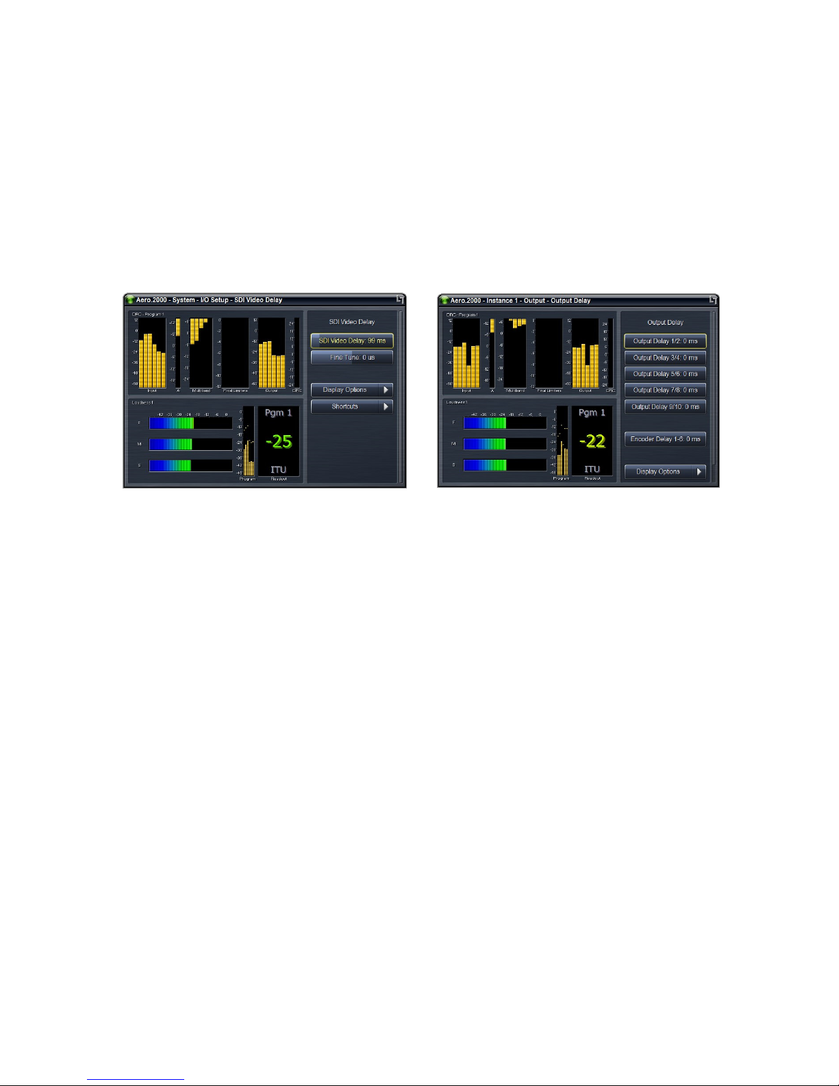
AERO.2000 User Guide July 2016
6. If this is the first time you are saving your working preset then select Save Preset As and
press Right.
7. Select alpha numeric characters using the Rotary and press Right after every selection to
create the name. When finished select Save and press Right.
8. Press Left to return to main menu.
L16/1/18039
Figure 5-5 Left: SDI video delay settings; Right: Output Delay settings available for each instance
5.8.6
5.8.6 Configuring Audio Delay
5.8.65.8.6
The calculations for video delay and audio delay are not difficult. An example for ATSC video is
given.
AERO.2000 audio processing/loudness control latency is 180 ms. AERO.2000 Dolby Digital
encoding latency is 64 ms. AERO.2000 total latency for processing and Dolby encoding is 244
ms.
Configuring Audio Delay
Configuring Audio Delay Configuring Audio Delay
• A video frame is 33.36 ms. 244ms/33.36ms = 7.31 frames.
• 8 frames is the nearest whole frame so viedo delay should be set for 266.88 ms.
• To make the Dolby Digital output audio latency match this value of video delay some
additional delay of the Dolby Digital output is required.
o Subtract the processing latency plus Dolby encoding delay from the total video
delay:
o 266.88 – 244 = 22.88ms.
o An additional Dolby Digital delay of 22.88 ms will match the Dolby output to the
video output. 22 ms is a good approximation.
o A lip sync test can be used to fine tune the value if necessary.
©2016 LINEAR ACOUSTIC INC. THE TELOS ALLIANCE. ALL RIGHTS RESERVED
Page 22
Page 37

AERO.2000 User Guide July 2016
• Linear PCM embedded in the SDI output can also be delayed to match the video delay.
This will allow lipsync between picture and both Dolby encoded audio and LPCM audio.
o Subtract LPCM audio delay from total video delay to get the additional LPCM
delay required.
o 266.88 – 180 = 86.88 ms of delay can be added to each LPCM pair.
o AES digital outputs can be used for in house monitoring and will be in sync with
picture.
o A lip sync test can be used to fine tune the value if necessary.
Note that each Instance has independent LPCM and Dolby encoded output delays.
To make the audio delay adjustments from the front panel:
1. Select Instance 1 and press Right to open the menu.
2. Select Output > Output Delay > Select any of the Output Delay adjustments and use the
rotary to set the delay in ms.
3. The DOLBY DIGITAL PLUS encoder delay is at the bottom of this menu.
4. Pressing Right while on any Output Delay adjustment will open a menu with fine
adjustment controls.
L16/1/18039
5.9
5.9 Front Panel
Front Panel Navigation
5.95.9
Front Panel Front Panel
We hope that after following along with the preceding front panel configurations using the
front panel is now a familiar task. Here are two tips to remember when working from the front
panel:
• If you ever get lost in the menu structure pressing the Left arrow key, several times, will
always take you back, one menu level at a time, to the AERO.2000 main screen.
• Remember that your location in the menu is always shown at the top of the front panel
display.
The next Section, Section 6, describes how to configure the AERO.2000 using NfRemote, a
comprehensive IP remote control application.
Section 7 contains a description of all of the configuration tasks necessary for a common use
case.
Navigation---- Conclusion
NavigationNavigation
Conclusion
ConclusionConclusion
©2016 LINEAR ACOUSTIC INC. THE TELOS ALLIANCE. ALL RIGHTS RESERVED
Page 23
Page 38

AERO.2000 User Guide July 2016
6666 Using NfRemote
Using NfRemote
Using NfRemoteUsing NfRemote
The Nf Remote IP remote interface software is a separate client application that can be
downloaded and installed on most recent desktop, laptop, or tablet PCs running Windows XP,
Vista, 7, 8, or 10. Touchscreen support is provided for touch-sensitive devices.
All of the AERO.2000 front panel parameter adjustments can also be made via the Nf Remote
client. The remote has additional capabilities:
• Streaming audio back over the local network to the host computer. Audio can be
monitored pre and post processing and at several points internal to the loudness
controller.
• Presets (System I/O setup, main upmix, local upmix, loudness control) can each be saved
to the host PC and restored from the host PC.
• The entire AERO.2000 configuration can be saved to and restored from the host PC.
• Presets and configurations can be shared between AERO.2000 units.
• Six meter configurations, each unique to a given PC, can be saved to the local PC and
recalled at the push of a button.
• Multiple NfRemote session can be run on a single PC for metering and control of
multiple AERO.2000 units.
• Multiple PCs can connect to AERO.2000 simultaneously.
Note!
L16/1/18039
If the AERO.2000 IP address is 127.0.0.1 this indicates that there is not a valid IP
connection to the AERO.2000.
If the AERO.2000 shows an IP address of 169.x.x.x it is connected to a valid
Ethernet port but it cannot a fetch a DHCP address or a fixed IP address has not
been set by the user.
6.1
6.1 Downloading NfRemote From the AERO.2000 HTTP server
Downloading NfRemote From the AERO.2000 HTTP server
6.16.1
Downloading NfRemote From the AERO.2000 HTTP serverDownloading NfRemote From the AERO.2000 HTTP server
These instructions assume that the IP address of the PC being used has been entered in the
AERO.2000 white list. If this has not been done, see section 5-4.
©2016 LINEAR ACOUSTIC INC. THE TELOS ALLIANCE. ALL RIGHTS RESERVED
Page 24
Page 39
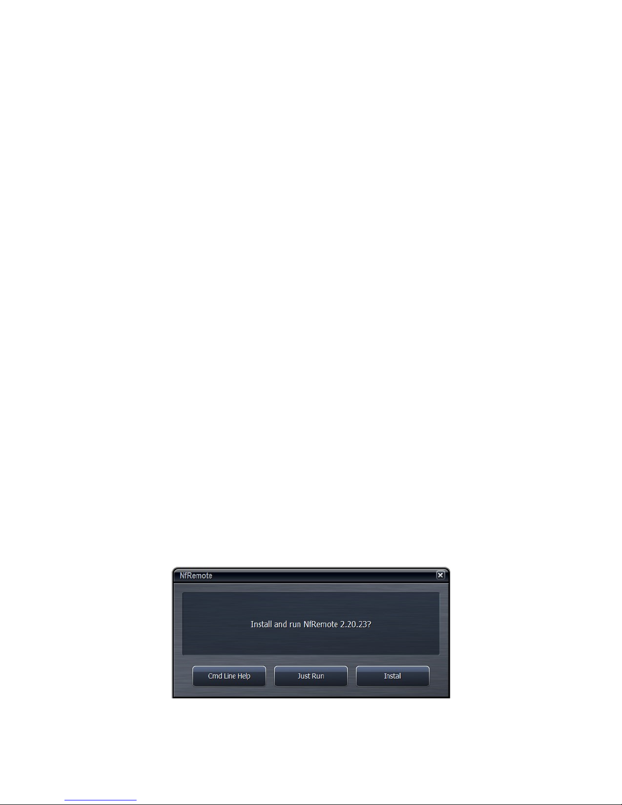
AERO.2000 User Guide July 2016
Make sure that your PC is in the same subnet as the AERO.2000 and connect to the AERO.2000
HTTP server using any browser. To do this enter the AERO.2000’s IP address in the browser
followed by the HTTP server’s port number, 7380.
• In some browsers you simply enter the address and port of the AERO.2000: For
example: 192.168.1.102:7380.
• In MS Internet Explorer you must enter: http://192.168.1.102:7380, replacing
192.168.1.102 with your AERO.2000’s IP address.
Right click on the NfRemote link in the HTTP server home page and save NfRemote.exe to your
PC. Locate the exe on your PC and launch the installer and select Install from the menu. Go to
6.3
6.2
6.2 Start NfRemote From a Copy on your PC
Start NfRemote From a Copy on your PC
6.26.2
Start NfRemote From a Copy on your PCStart NfRemote From a Copy on your PC
The NfRemote version for your AERO.2000 is always available in the HTTP server and can be
accessed as described above. The same NfRemote version is also on the USB flash drive that
comes, in the box, with each new unit. The latest version of NfRemote can also be downloaded
from our website.
L16/1/18039
Every new version of NfRemote is backward compatible with all previous versions. The same
NfRemote is used for configuration, control and metering of AERO.10/100/1000/2000 units.
Always update your NfRemote when you update your AERO.2000 software. Below we will
explain how to get started with NfRemote if you have the USB flash drive or you have
downloaded NfRemote.exe from our website.
Once a valid IP address is displayed on the AERO.2000 make sure that your PC is in the same
subnet (but not the same IP address as the AERO.2000). Find the NfRemote.exe on the USB
flash drive or on your PC and drag it to your desktop. Continue with 6.3.
6.3
6.3 Getti
Getting Connected
6.36.3
GettiGetti
Click on the NfRemote link in the HTTP server home page and save the exe to your PC. Locate
the exe on your PC and launch the installer and select Install from the menu. See Figure 6-1.
ng Connected
ng Connectedng Connected
©2016 LINEAR ACOUSTIC INC. THE TELOS ALLIANCE. ALL RIGHTS RESERVED
Figure 6-1 Remote software installer
Page 25
Page 40
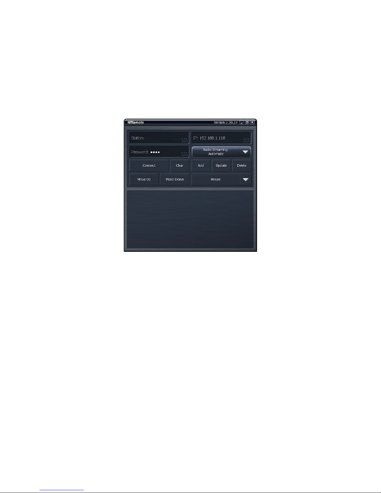
AERO.2000 User Guide July 2016
L16/1/18039
Launch the NfRemote software (New Framework Remote) and enter the AERO.2000 IP address,
and password. You can also add a name for the AERO.2000 and click Add so that NfRemote
remembers the entry. Click Connect and NfRemote should connect to the AERO.2000. Of
course the PC must be connected to the network and be addressed in the same subnet as the
AERO.2000. On the work bench a PC may connected directly to the Ethernet port on the
AERO.2000 using a straight Ethernet cable for the initial setup.
Figure 6-2 NfRemote start screen
Click Connect and the connection screen will be displayed and NfRemote will open. See Figure
6-3
©2016 LINEAR ACOUSTIC INC. THE TELOS ALLIANCE. ALL RIGHTS RESERVED
Page 26
Page 41
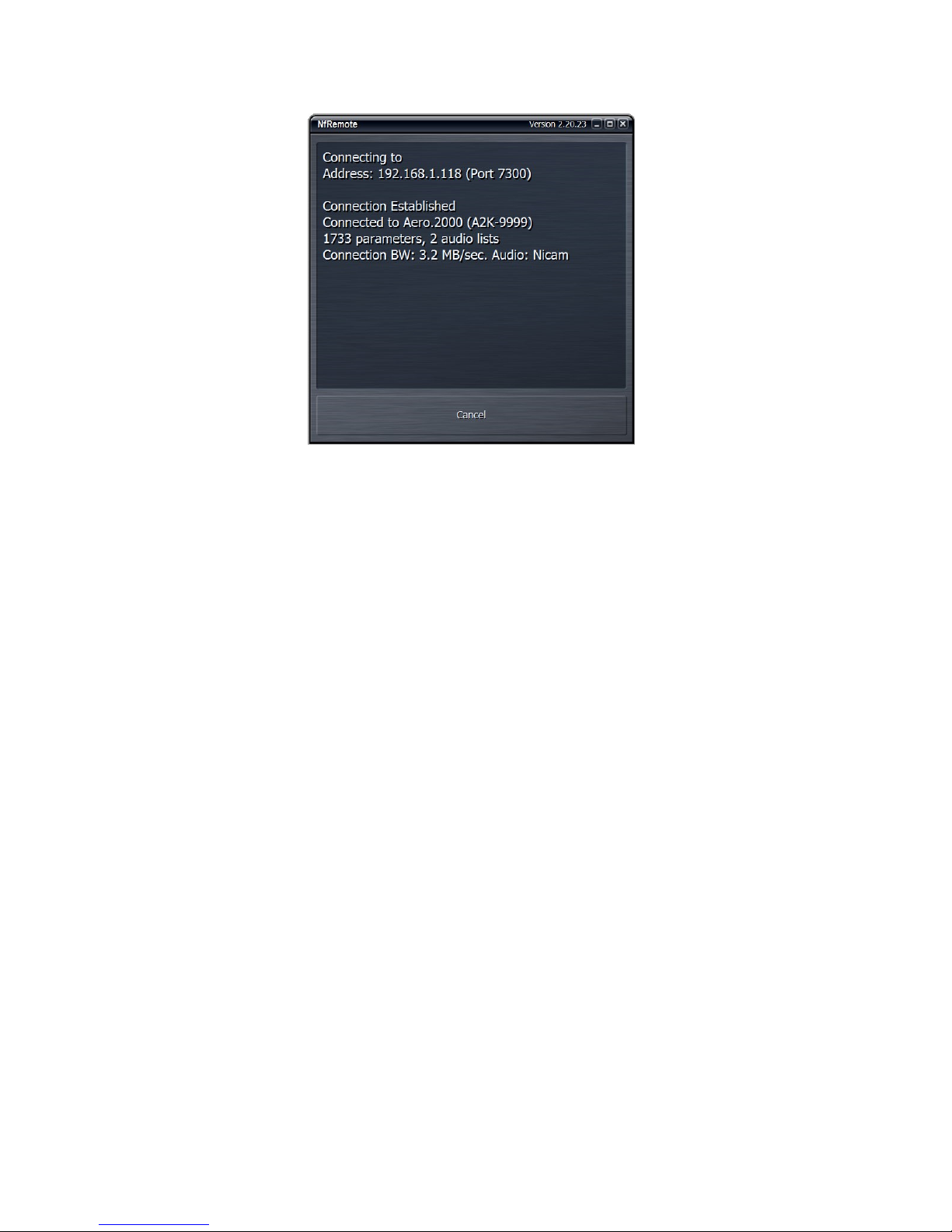
AERO.2000 User Guide July 2016
Figure 6-3 NfREmote connection screen
If NfRemote fails to connect make sure that there is an IP address shown on the unit’s front
panel lock display. If the front panel is unlocked use the front panel controls and navigate to:
L16/1/18039
System > Network Access > IP Configuration and read the IP address here.
Ensure that your PC is in the same subnet and has the same subnet mask and does not have the
same IP address. Ensure that there are no address conflicts in the subnet. If there are still
connection problems connect a PC directly to the AERO.2000 Ethernet port (not the reserved
Ethernet port!). A straight Ethernet cable can be used. Change your PC’s Ethernet port IP
address to something in the same subnet and subnet mask as the AERO.2000. After
establishing a connection in this manner you can trouble shoot the network connection.
6.4
6.4 Using NfRemote
Using NfRemote
6.46.4
Using NfRemoteUsing NfRemote
After successful connection, Nfremote starts at the Home Screen. The remote interface screen
is fully re-sizeable and can be adjusted in the same manner as any MS Windows app screen.
That is, via handles at each corner. The displays and windows will dynamically adjust
themselves to make the best use of available screen real estate as you resize the window.
The first time NfRemote starts it is in Tree navigation mode. Tree navigation works in the same
way that front panel navigation works. Each time you click a menu item it opens the next menu
level and so on down through the menus. Breadcrumbs are shown in the space below the
meters. In Figure 7-4 you are in the Home menu. Home is shown at left below the meters. See
Figure 6-4.
©2016 LINEAR ACOUSTIC INC. THE TELOS ALLIANCE. ALL RIGHTS RESERVED
Page 27
Page 42
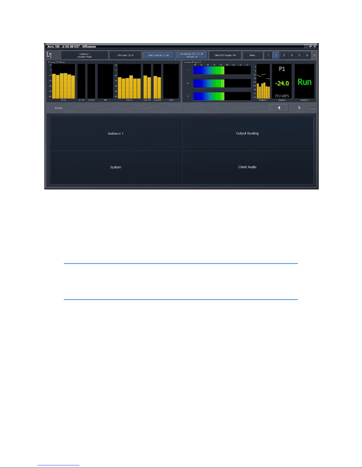
AERO.2000 User Guide July 2016
L16/1/18039
Figure 6-4 Home screen, Tree mode (default)
At the top of NfRemote are displays that indicate the AERO.2000’s CPU load, client volume
(streaming audio), headphone volume, and the host PC’s CPU load. See Figure 6-4. In some
cases, when the display is made smaller, these controls combine and a drop-down arrow
appears allowing you to activate individual controls.
Note!
In no case should the AERO.2000 CPU load exceed 80% for any length of time.
This should be a rare occurrence and may be due to an excessive number of
simultaneous NfRemote connections.
Click the Menu button (top right) to select Tree or Tabbed navigation, full screen meter display,
lock the window’s onscreen position, maximize the window, enter full screen mode, or close
the window. When the display is in meters only mode, place the mouse in any meter window
and left click to return to the NfRemote configuration screen.
To the right of the Menu button are six Display Presets that quickly recall display configurations.
Simply select a display preset from 1 to 6 and configure the display settings. The AERO.2000
remote software first appears with display preset 1 active. Any changes made to the screen
(i.e., selecting between navigation modes, resizing window sections, or choosing the number
and/or type of display windows visible) are automatically saved in real time. Switching back to
this preset, from any other preset, automatically recalls your saved settings. Each Display
©2016 LINEAR ACOUSTIC INC. THE TELOS ALLIANCE. ALL RIGHTS RESERVED
Page 28
Page 43
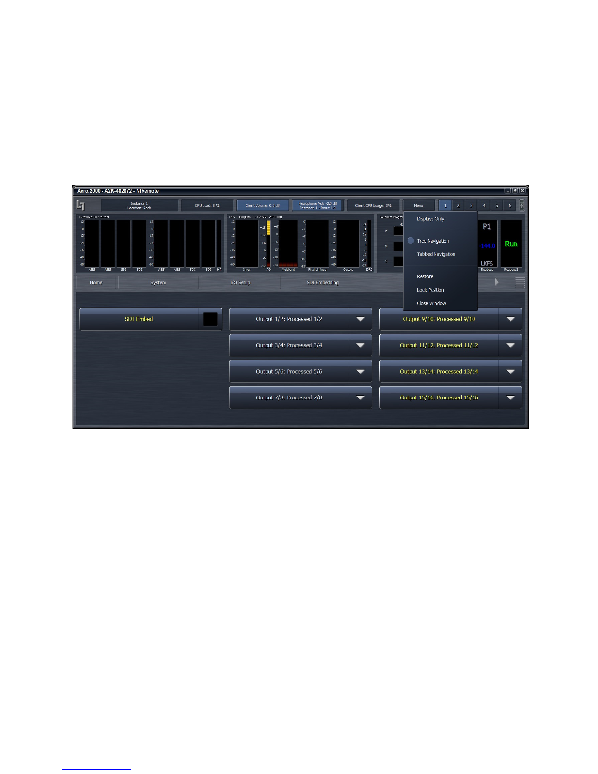
AERO.2000 User Guide July 2016
Setting is saved on the local PC so every PC that connects can have 6 unique metering
configurations instantly available.
Instance and Client Audio configuration screens have Display Settings in the lower right corner
of the settings tabs. From any configuration screen you can click on any meter to go directly to
the display setup page and specific settings for that meter. See Figure 6-5.
L16/1/18039
Figure 6-5 NfRemote Tree interface, Menu drop down
Note that the breadcrumbs show where you are in the menu:
• System > I/O Setup > SDI Embedding
• The selections for SDI embedding are shown at the bottom of the display
6.5
6.5 Tree
Tree and Tabbed Navigation
6.56.5
Tree Tree
Tree and Tabbed navigation refer ONLY to how information and controls are displayed on the
screen, not the number of controls available or their precision.
The default mode is Tree Navigation (shown in Figures 6-4 and 6-5). This devotes the top of the
screen to meter displays while the bottom is reserved for menus and controls. The area
between these two sections displays breadcrumbs indicating where you are in the menu
hierarchy. The on-screen arrows can be clicked to navigate between the most recently visited
controls. The “ribbed” section of the display, to the far right of the arrows, allows the top and
©2016 LINEAR ACOUSTIC INC. THE TELOS ALLIANCE. ALL RIGHTS RESERVED
and Tabbed Navigation
and Tabbed Navigationand Tabbed Navigation
Page 29
Page 44
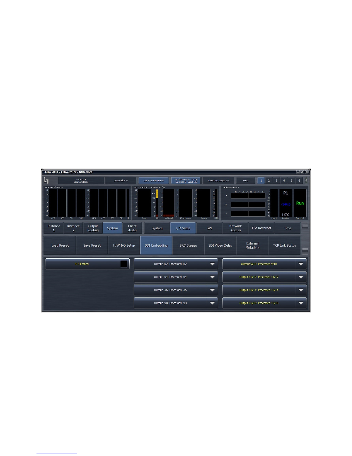
AERO.2000 User Guide July 2016
bottom sections to be resized. Place your pointer in the ribbed area and left click to change the
relative sizes of the meters and controls. See Figure 6-5, above.
In the Tabbed mode, all menus and all controls are displayed on the screen simultaneously (see
Figure 6-6 below). This mode inherently makes menus, controls, and their labels smaller. This
mode works best when the remote software window can be made large enough so that all text
items can be easily read. In Tabbed mode you have direct access to all menus items and
associated controls without having to step through the menu structure in sequence.
Figure 6-6 shows the same menu location as Figure 6-5 but in Tabbed view. Notice that you can
see all of the sub-menus of System (top row, right side), all of the sub-menus of I/O Setup in the
center section, and all of the available selections under SDI embedding in the bottom section.
There are two size adjustments in Tabbed view. One adjusts the meter vs menu item size and
the other the relative sizes of the center and lowest section of the menus.
L16/1/18039
Figure 6-6 NfRemoteTabbed mode
6.6
6.6 Configuring
Configuring Meter
6.66.6
Configuring Configuring
Although up to eight meters can be shown on the NfRemote screen at once, each additional
meter takes away screen space from the others. Depending on your monitor size you may find
it practical to limit the number of meters on any one screen. Display presets can be used to
quickly switch between different meter selections. Display presets can also be used to create
full screen meter displays. More meters can be used for full screen view than are practical
when the menus are visible.
©2016 LINEAR ACOUSTIC INC. THE TELOS ALLIANCE. ALL RIGHTS RESERVED
Meter Display
Meter Meter
Displayssss
DisplayDisplay
Page 30
Page 45
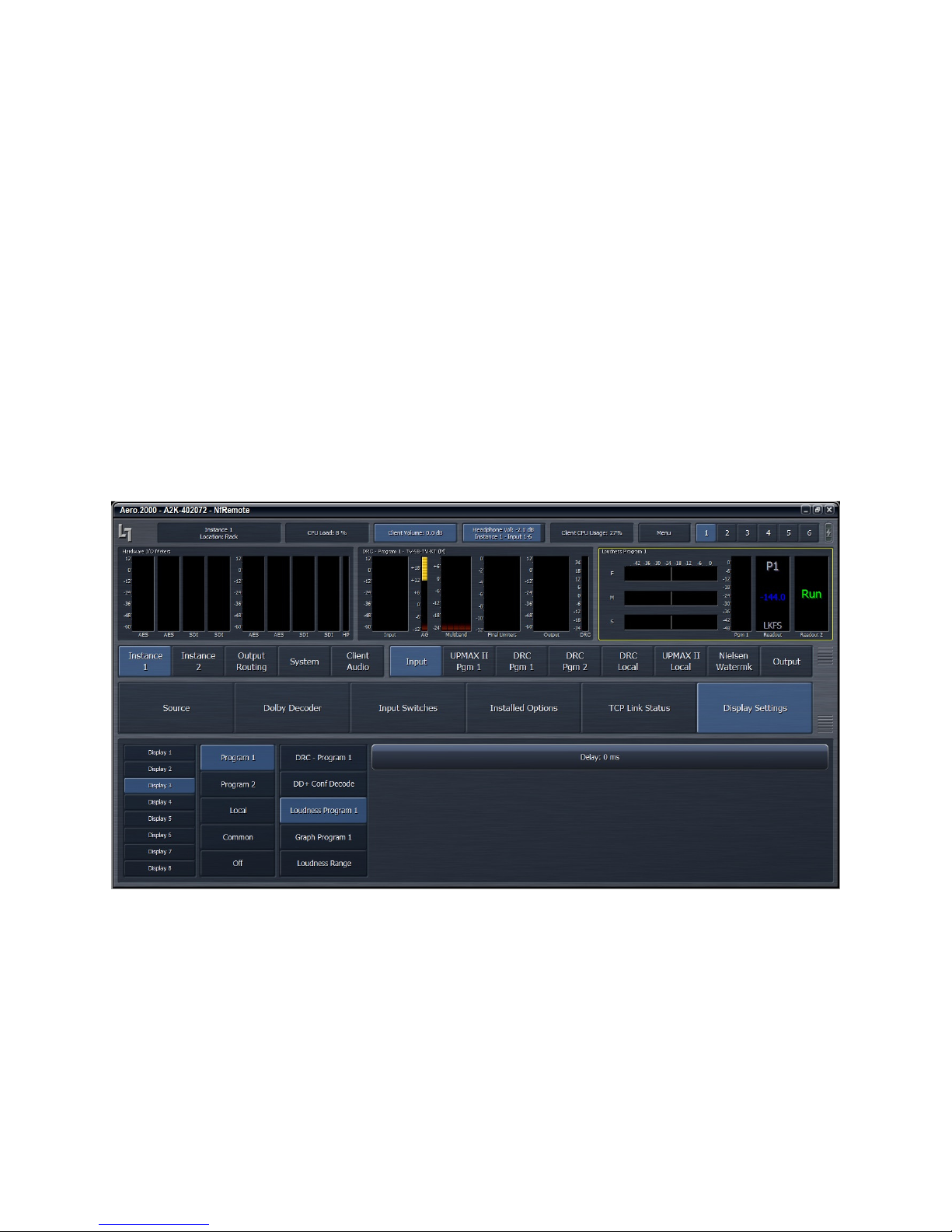
AERO.2000 User Guide July 2016
L16/1/18039
Note that the display settings for each Instance are unique. All 6 display settings in Instance 1
are entirely independent of the settings in Instance 2. If you have 2 Instances loaded in your
AERO.2000 then display setups will need to be created for Instance 2 as well. All of the meter
setups described here are done in Instance 1. By choosing Instance 2 all of these setups can be
duplicated for the second Instance. The meter configurations described here will be used in the
I/O and preset configuration examples that follow.
To setup display preset 1 start by clicking display preset 1 (next to Menu button) then click on:
1. Instance 1 > Input > Display Settings
2. Display 1 > Common > Hardware I/O
3. Display 2 > Program 1 > DRC-Program 1
4. Display 3 > Program 1 > Loudness Program 1
5. See Figure 6-7
Click display preset 2 and then click:
1. Display 1 > Program 2 > DRC-Program 2
2. Display 2 > Program 2 > Loudness Program 2
3. Display 3 > Program Local > DRC- Local
4. Display 3 > Program Local > Loudness Local
©2016 LINEAR ACOUSTIC INC. THE TELOS ALLIANCE. ALL RIGHTS RESERVED
Figure 6-7 NfRemote Display Preset 1
Page 31
Page 46

AERO.2000 User Guide July 2016
L16/1/18039
Click display preset 3 and then click:
1. Display 1 > Program 1 > Loudness-Program 1
2. Display 2 > Program 1 > Graph Program 1
3. Display 3 > Program 2 > Loudness Program 2
4. Display 3 > Program 2 > Graph Program 2
5. Local Display 3 > Program Local > Loudness Local
6. Display 3 > Program Local > Graph Local
To remove a display, click on Display Settings, select any Display and select Off from the menu.
To aid in setting up the DRCs (loudness controllers) and also to evaluate content pre and post
processing there are several audio analyzers available in the Display settings menus:
For each Pgm there are meters for:
• DRC activity
• DOLBY DIGITAL PLUS Confidence (decode)
• ITU Loudness Meter
• ITU Loudness Graph
• EBU Loudness Range.
• True Peak readings are shown on each Program Loudness meter.
• When a Program Loudness Meter is set to measure Integrated Loudness the
measurement is started and stopped from the Instance x > Output > Meter > PGM
window. The Program Loudness meter will indicate if the integration is in Run or Stop
mode.
Common meters include:
• Instance I/O
• Hardware I/O
• Oscilloscope
• RTA
• FFT
The oscilloscope, RTA and FFT are valuable monitoring and diagnostic tools that can measure
and display signals from myriad patch points within AERO.2000. Extensive setup controls are
provided for these meter types. An example is shown in Figure 6-8, below.
©2016 LINEAR ACOUSTIC INC. THE TELOS ALLIANCE. ALL RIGHTS RESERVED
Page 32
Page 47
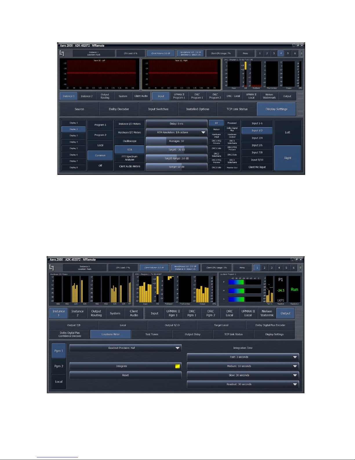
AERO.2000 User Guide July 2016
Figure 6-8 Settings for the RTA meter
L16/1/18039
6.7
6.7 Configuring Loudness Meters
Configuring Loudness Meters
6.76.7
Configuring Loudness MetersConfiguring Loudness Meters
ITU-BS.1770-3 loudness meters for each output in each Instance are provided. The loudness
meter is tied to a specific Instance and program output and the meter settings can be different
for each program output. This allows program-specific monitoring if desired. The loudness
meter setups are located within Instance 1 (or 2) > Output > Loudness Meter settings. See
Figure 6-9, below.
©2016 LINEAR ACOUSTIC INC. THE TELOS ALLIANCE. ALL RIGHTS RESERVED
Figure 6-9 Settings for the program-specific ITU meter
Page 33
Page 48

AERO.2000 User Guide July 2016
The integration time of the 3 bar graph meters can be chosen as well as the integration time of
the digital readout. The integration of the digital readout can also be manually controlled to
measure specific programs or over specific time periods.
Note that the meter settings available here do not affect the loudness log readings.
Remember that the meter setup for each Instance is independent. To see both instances at the
same time two NfRemote sessions can be opened on the same PC at the same time. One
session can view Instance 1 and the second can view Instance 2.
6.8
6.8 Configuring AERO.2000
Configuring AERO.2000 I/O
6.86.8
Configuring AERO.2000 Configuring AERO.2000
Connect your SDI program source to the AERO.2000 SDI input. A typical SDI embedded audio
source channel map is:
• Embedded pair 1/2: Stereo or 5.1 Lf/Rf
• Embedded pair 3/4: Silent or C/LFE
• Embedded pair 5/6: Silent or Ls/Rs
• Embedded pair 7/8: Silent or channel 7 only SAP (secondary audio program) or
descriptive video service
• Embedded pair 9/10 to 15/16: Silent or not used.
A typical SDI embedded audio output channel map could be:
• Embedded pair 1/2: Dolby Digital bitstream (2-ch up through 5.1-ch)
• Embedded pair 3/4: SAP/DVS (LPCM)
• Embedded pair 5/6: Not used
• Embedded pair 7/8: Not used
• Embedded pair 9/10 to 15/16: Not used.
We will use this example to configure the AERO.2000. Some adjustments need to be made if
your channel map is not the same as the example here.
I/O
I/OI/O
L16/1/18039
6.8.1
6.8.1 SDI Embedding
6.8.16.8.1
©2016 LINEAR ACOUSTIC INC. THE TELOS ALLIANCE. ALL RIGHTS RESERVED
SDI Embedding
SDI EmbeddingSDI Embedding
1. Read section 2.7.5 if you have not already read it.
2. Select display preset 1 (next to Menu at top left of NfRemote screen)
3. Select System > I/O Setup > SDI Embedding. The screen looks like Figure 3-9, below.
4. Click SDI Embed to enable embedding. The “enabled” indicator turns yellow.
5. Click the Output 1/2 drop down and select Processed 1/2.
6. Repeat for each Output drop down, 3/4 through 15/16. See Figure 6-10 for selections.
Page 34
Page 49
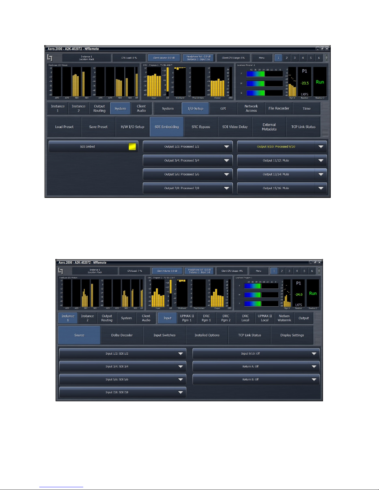
AERO.2000 User Guide July 2016
Figure 6-10 Enable embedding and select embedded output sources
L16/1/18039
6.8.2
6.8.2 Instance 1 Input Sources
6.8.26.8.2
Instance 1 Input Sources
Instance 1 Input SourcesInstance 1 Input Sources
Select Instance 1 > Input > Source. The screen looks like Figure 6-11, below.
1. Select Input 1/2, drop down and select SDI 1/2.
©2016 LINEAR ACOUSTIC INC. THE TELOS ALLIANCE. ALL RIGHTS RESERVED
Figure 6-11 Select Instance 1 input sources
Page 35
Page 50
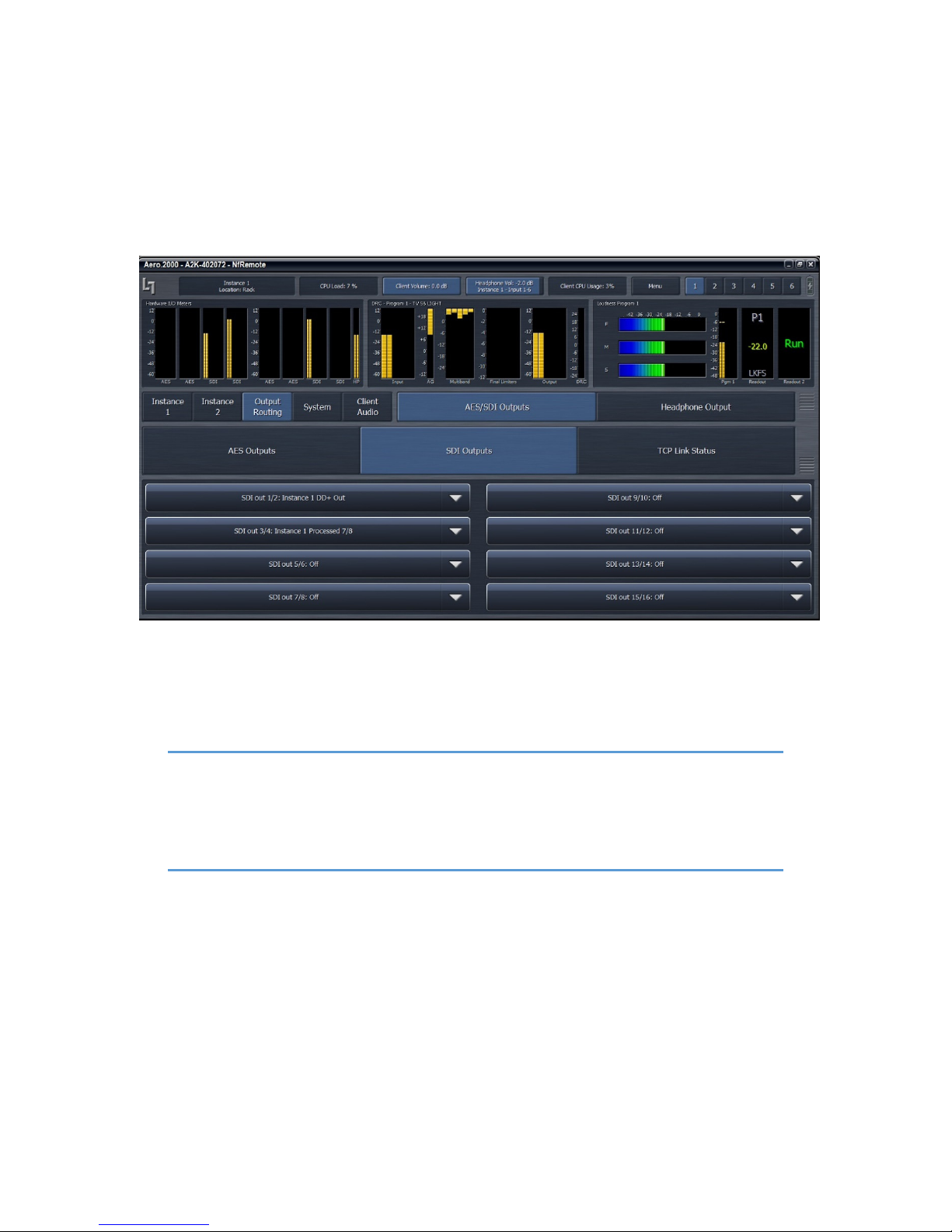
AERO.2000 User Guide July 2016
2. Select Inputs 3/4, 5/6, 7/8, and 9/10 and select the SDI inputs as shown in Figure 3-10.
6.8.3
6.8.3 Output Routing
6.8.36.8.3
Output Routing
Output RoutingOutput Routing
Select Output Routing > AES/SDI Outputs > SDI Outputs.
The screen looks like Figure 6-12, below.
L16/1/18039
Figure 6-12 Select Output Routing
• Select SDI Out 1/2: Instance 1 DD+ Out
Note!
The DD+ Out can be AC3 or H-AC3. This selection is made by navigating to:
Instance 1 > Output > DD+ Encoder > Codec: and selecting from the Drop Down.
Other parameters for the selected Dolby encoder can also be made on this
screen.
• Select SDI Out 3/4: Instance 1 Processed 7/8
• Select SDI out 5/6 through SDI out 15/16 to Off.
6.9
6.9 Using the Meters
Using the Meters
6.96.9
Using the MetersUsing the Meters
Looking at the Hardware I/O meter (far left) in Figures 6-11 you can see that:
• The SDI source has 6 channel surround content on the first 3 pairs.
©2016 LINEAR ACOUSTIC INC. THE TELOS ALLIANCE. ALL RIGHTS RESERVED
Page 36
Page 51

AERO.2000 User Guide July 2016
L16/1/18039
• There is no audio on pair 4 (7/8).
• Pair 5 (9/10) has a high level signal.
Looking at Figures 6-10 and 6-11 and 6-12 it is clear that the signal on SDI input pair 9/10 is
unchanging. This is characteristic of a Dolby E, Dolby Digital or Dolby Digital Plus encoded pair.
The SDI signal source has a Dolby E signal on pair 5 (9/10).
Clearly visible in Figures 6-10 and 6-11:
• Audio output is seen on SDI output pairs 1, 2 and 3. (channels 1/2, 3/4, 5/6)
• In addition, there is audio on pair 5. (channels 9/10)
In Figure 6-12, after we have configured the Output routing, the only output is the AERO.2000
Dolby AC3 encoder output on pair 1. (channels 1/2)
Also note that in Figure 6-11 there is a 5.1 surround source program on inputs 1/2, 3/4, 5/6 and
the DRC-Program 1 meter shows it is processing a 5.1 source.
In Figure 6-12 the source is stereo and the DRC-Program 1 meter shows it is processing the
stereo source.
The 5.1 DRC 1 will properly control a stereo source applied to Input 1/2. Upmixing a stereo
source is not required!
However, if the source is full time stereo the 3/4 and 5/6 inputs can be muted. This will
automatically switch the Dolby AC3 or DD+ encoder to stereo mode, which changes the acmod
metadata of the Dolby encoded bitstream to 2/0. See Figure 6-13 below.
©2016 LINEAR ACOUSTIC INC. THE TELOS ALLIANCE. ALL RIGHTS RESERVED
Page 37
Page 52
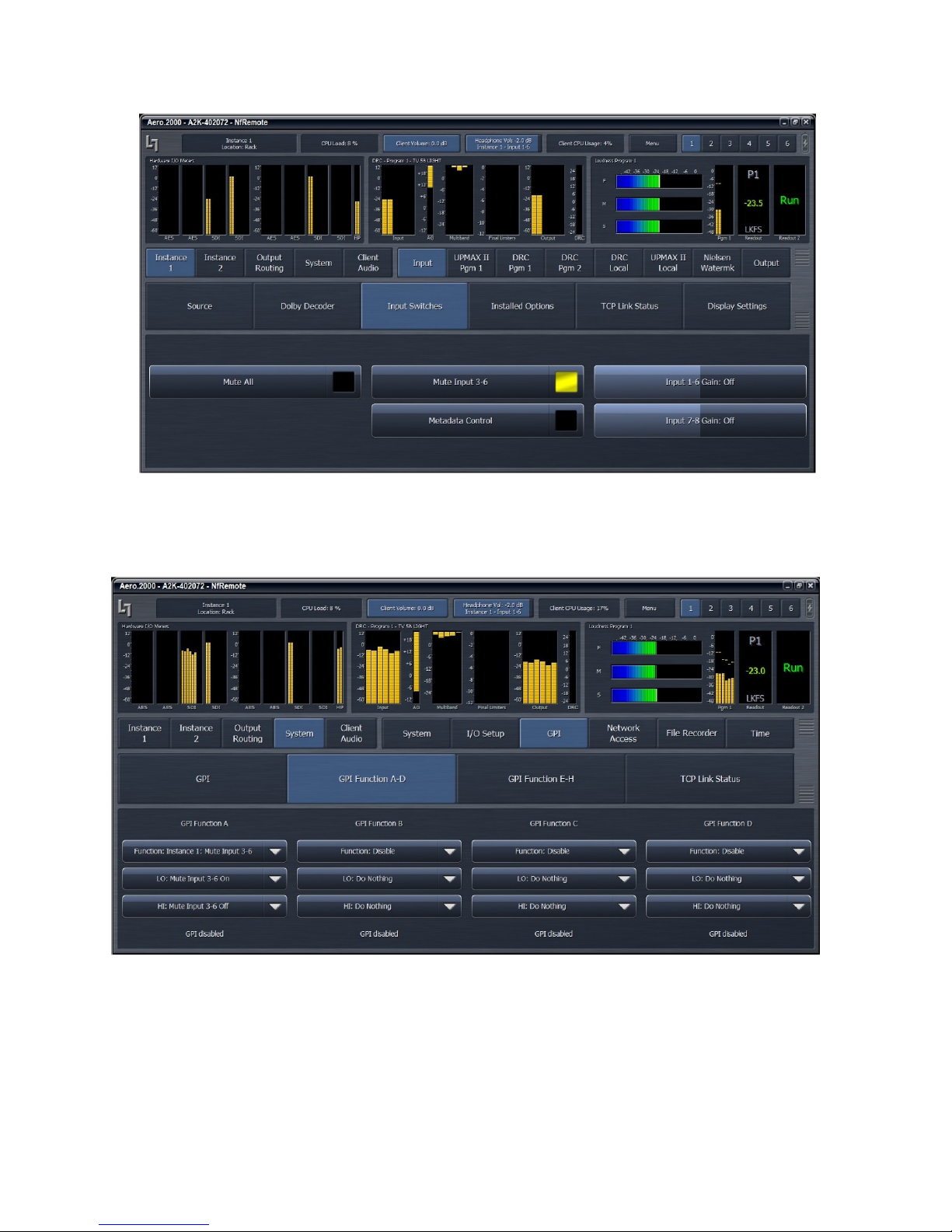
AERO.2000 User Guide July 2016
L16/1/18039
Figure 6-13 Mute Input 3-6
The change between Dolby surround encoding for 5.1 surround and 2.0 can be automated
using GPI or IP commands. See Figure 6-14, below.
Figure 6-14 GPI control of channel 3-6 muting
These examples illustrate how the meters help in configuring the AERO.2000. Changes in the
configuration can be immediately seen on the meters.
©2016 LINEAR ACOUSTIC INC. THE TELOS ALLIANCE. ALL RIGHTS RESERVED
Page 38
Page 53

AERO.2000 User Guide July 2016
6.10
6.10 UUUUPPPPMAX
6.106.10
UPMAX II with AutoMAX source detection provides 5.1 surround viewers with a consistently
excellent surround experience and is the industry standard upmix processor. Uniquely, UPMAX
II does not rely on detection of out-of-phase audio to produce the surround channel signals.
This is of critical importance today because of the widespread use of low bitrate audio coding
for delivery of some programming. This can sometimes cause coding artifacts to be unmasked
and reproduced by the surround channels. UPMAX II avoids this by its very design and
unmasked artifacts are minimized. It produces an upmix that, when downmixed, provides a
near identical stereo output compared to the original. It also does a superb job of keeping
dialogue out of the rear channels. Viewers listening in stereo get a consistently good downmix.
It is a win-win situation.
6.10.1
6.10.1
6.10.16.10.1
1. Navigate to Instance 1 > UPMAX II Pgm1 > Load Preset.
2. Select the “UPMAX Center Diverged” preset.
3. Click Main Settings
MAX
MAXMAX
Enable and Configure UPMAX
Enable and Configure UPMAX
Enable and Configure UPMAXEnable and Configure UPMAX
L16/1/18039
4. Click Upmix Enable to make the indicator yellow.
5. Select the Auto Mode drop down and select Auto Mode On. See Figure 6-15.
6. Click Transitions
7. Click Discreet ->Upmix drop down and select Very Quick
8. Click Upmix -> Discreet drop down and select Quick
9. The setting in 7, above, will keep the sound stage from shifting when a stereo program
follows a 5.1 program. When a 5.1 program follows a stereo program the crossfade can
be slightly slower (number 8 above) but the center channel still must be passed quickly.
10. Click Save Preset and save the changes as a new name.
©2016 LINEAR ACOUSTIC INC. THE TELOS ALLIANCE. ALL RIGHTS RESERVED
Page 39
Page 54
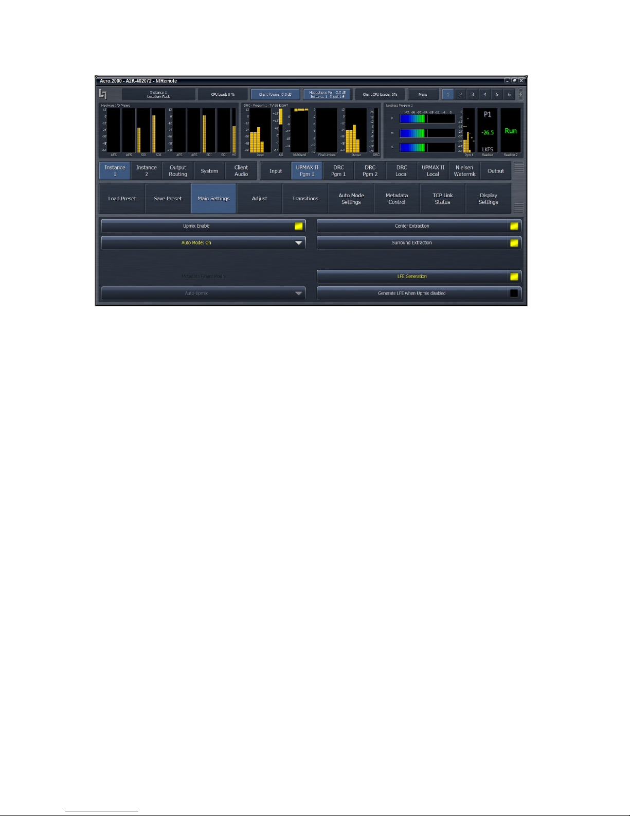
AERO.2000 User Guide July 2016
Figure 6-15 Configure UpMAX II
L16/1/18039
6.10.2
6.10.2
6.10.26.10.2
UUUUPPPPMAX
MAX Operating Modes
1. Upmix Disabled.
a. Stereo sources routed to Input 1/2 are sent to the loudness controller
b. 5.1 surround sources routed to Inputs 1/2, 3/4, 5/6 are sent to the loudness
2. Upmix Enabled and Auto: Off.
a. The source routed to Input 1/2 will always be upmixed
b. A surround source routed to Inputs 1/2, 3/4, 5/6 will have its Lf and Rf pair
Operating Modes
MAXMAX
Operating ModesOperating Modes
controller
upmixed as if it were a stereo source
©2016 LINEAR ACOUSTIC INC. THE TELOS ALLIANCE. ALL RIGHTS RESERVED
Page 40
Page 55

AERO.2000 User Guide July 2016
3. Upmix Enabled and Auto: On.
a. 5.1 surround sources routed to Inputs 1/2, 3/4, 5/6 are passed through to the
loudness controller
b. If Input channels 3, 5 and 6 are below the 5.1 surround detection threshold (this
defines a stereo source on 1/2) the unit will crossfade to an upmix of channels 1
and 2.
c. Audio above the 5.1 surround detection threshold level, on channels 3, OR 5 OR
6, will result is a crossfade back to 5.1 pass through mode.
d. The 5.1 threshold and crossfades are set here:
i. Instance 1 > UpMAX II Pgm 1 > Auto Mode Settings > Discrete Detection
Threshold:
ii. Instance 1 > UpMAX II Pgm 1 > Transitions > Discrete -> Upmix
iii. Instance 1 > UpMAX II Pgm 1 > Transitions > Upmix -> Discrete
4. Upmix Enabled and Auto: Metadata Auto/No
5. Upmix Enabled and Auto: Metadata Yes/Auto
6. Upmix Enabled and Auto: Metadata Yes/No
L16/1/18039
6.10.3
6.10.3
6.10.36.10.3
There are many adjustable parameters that allow UPMAX to be tuned to suit the source
material. The flexibility allows UPMAX and AutoMAX to be used by broadcasters of sports,
music, entertainment, and mixed content and for both live and recorded programs.
A preset that we call “Center Diverged is used by a great many broadcasters that have varied
content throughout the day. The settings are shown in Figures 6-16, 6-17 and 6-18, below. TV
channels that specialize in a particular content type such as sports, old TV shows or movies can
finely tune UPMAX to present the best possible 5.1 surround sound from their stereo content.
Adjusting the Upmix
Adjusting the Upmix
Adjusting the UpmixAdjusting the Upmix
1. UPMAX Parameters: Instance 1 > UpMAX II Pgm 1 > Main Settings >
a. Center Extraction enables the creation of a center channel from the stereo
source
b. Surround Extraction enables the creation of the Ls and Rs rear channels from the
stereo source.
c. LFE Generation enables the creation of a .1 (LFE) channel that is downmix
compatible, low pass filtered, and bass enhanced low frequency content from
the L, C and R channels.
d. Generate LFE When Upmix Disabled enables the addition of the LFE content
described above to the existing 5.1 surround content.
©2016 LINEAR ACOUSTIC INC. THE TELOS ALLIANCE. ALL RIGHTS RESERVED
Page 41
Page 56

AERO.2000 User Guide July 2016
2. UpMAX Parameters: Instance 1 > UpMAX II Pgm 1 > Adjust >
a. Center Exclusivity
i. Controls how much of the Lf/Rf audio that UpMAX uses for center
channel audio is removed from Lf and Rf channels
ii. 0 % removes little of the audio used for center channel from Lf/Rf
iii. 100% removes most of the audio used for center channel from Lf/Rf
iv. Recommended starting value 60%
b. Upmix Center Width
i. Controls how much of center channel audio is distributed to Lf/Rf
ii. Total power is preserved
iii. 0% and no center channel audio is spread to Lf/Rf
iv. 100% and center channel level is 0 dB and all of the center is in Lf/Rf
v. Recommended starting value 33%
c. 5.1 Center Width
i. Affects the center channel spread in 5.1 surround sources
ii. Total power is preserved
iii. Controls how much of center channel audio is distributed to Lf/Rf
iv. 0% and no center channel audio is spread to Lf/Rf
v. 100% and center channel level is 0 dB and all of the center is in Lf/Rf
vi. Recommended starting value 0%
d. Center Level
i. Adjusts level of center channel in UpMAX output
ii. Adjustment range is +/- 6dB
iii. Recommended starting value 0 dB
e. LFE level
i. Sets level of LFE channel
ii. Adjustable from -18 dB to 0 dB
iii. Recommended starting value -10dB
f. Surround Depth
i. Controls the amount of suitable Lf/Rf content that UpMAX uses to create
the surrounds
ii. 0% and the surround level is 0 dB
iii. 100% and UpMAX uses all of the appropriate Lf/Rf audio for Ls/Rs
iv. Recommended starting value 100%
g. Surround Width
i. Controls how much of the surround content is shared between Ls and Rs
channels.
L16/1/18039
6.11
6.11 Loudness Control
6.116.11
The heart of the AERO.2000 is found in the DRC settings. This is where program loudness
control takes place. There are a number of factory presets and they are found here:
©2016 LINEAR ACOUSTIC INC. THE TELOS ALLIANCE. ALL RIGHTS RESERVED
Loudness Control
Loudness ControlLoudness Control
Page 42
Page 57

AERO.2000 User Guide July 2016
Instance 1 (or 2) > DRC Program 1 (or 2 or Local) > Load Preset.
We recommend starting with a factory preset and modifying it, if necessary, to suit your needs.
Which preset you choose and what changes you make depends on your source material and
what your goals are for the audio you broadcast. A few guidelines are presented here and
descriptions of the factory presets are found in section 7.8.2.
We also highly recommend saving each audio program’s preset with a name that identifies the
program. For example, if you decide to use TV 5B Light on multiple channels then save each
program’s preset with a unique name; TV 5B Light KWXY Main and TV 5B Light KWXY SAP. If
any changes are made, however small, to the TV 5B Light KWXY Main preset the changes will
not affect the SAP channel. If TV 5B Light is used for multiple audio programs then any change
in the preset will affect every program using that preset.
6.11.1
6.11.1
6.11.16.11.1
If the dialogue level of 100% of the content you record, produce, create, ingest, and receive
were recorded at the same level then loudness control would be easy. In the real world a
typical television station, or channel, receives content from many sources. Dialogueue levels,
let alone the average program levels, are not consistent. Controlling the loudness of the
program material delivered to viewers, and especially the program to program level changes, is
one of the original concepts behind Linear Acoustic AEROMAX processing which has been in
place long before loudness regulations.
A viewer’s home is not the same listening environment as a movie theater or audio mix room or
a mixing theater! Home viewers listen at lower levels than professionals do when mixing and
reviewing material. A majority of viewers are also listening to programs on the small, low
power, rear or down facing speakers in the typical thin panel TV. The proper (and judicious) use
of noise reduction, AGC, equalization, wideband and/or multiband compression and look ahead
limiting can be used to help recreate the experience at home that the program creator had in
mind in the mix room. There is the capability to improve the audio quality of older content
that is not up to today’s audio quality standards. There is also the power to help automated
operations to achieve more consistent audio for live events, live news, and switching between
local, syndicated, commercial, promotional and network content.
The ability of AERO.2000 processing and loudness control to provide all of these functions in a
flexible, high quality and reliable fashion has made Linear Acoustic the choice of some of the
largest broadcasters in the world for over 14 years. The continued increase of loudness
regulation worldwide is the latest reason for continuing to expand and refine the capabilities of
the AERO processors.
What does all of this mean to you, the user?
Loudness Control Guide
Loudness Control Guide
Loudness Control GuideLoudness Control Guide
L16/1/18039
©2016 LINEAR ACOUSTIC INC. THE TELOS ALLIANCE. ALL RIGHTS RESERVED
Page 43
Page 58

AERO.2000 User Guide July 2016
If the loudness level of the content that you play varies over +/- 10 dB range around your target
LKFS level then your primary concern is going to be loudness control. If your content varies +/6 dB LKFS (or less) around your target level then much more attention can be given to
delivering a faithful reproduction of the program instead of controlling loudness. Some
broadcasters feel that delivering a faithful reproduction of the source material at the correct
level, no matter how good or bad the source may be, is a worthy goal. The AERO.2000
processor can help broadcasters attain any and all of these goals. If the audio levels of your
content are nearly correct before playout then start with the TV 5B LIGHT preset. If your levels
are not very well controlled, start with TV 5B GEN. From fully wideband to multiband (using
two to five bands bands of multiband processing), every AERO processor is capable is meeting
any particular needs. A brief description of the factory presets is below.
6.12
6.12
6.126.12
This section lists each preset in alphabetical order, as they appear in the AERO.2000 and the
remote interface.
All presets are adjusted so that with the input content averaging around -24 LKFS, the output is
optimized to produce -24 LKFS, ± 2 dB per ATSC A/85.
Compliance with stricter loudness regulations found in some countries can be achieved by using
the new advanced ITU (AI) limiter (software V0.13.55 and later).
Factory Presets
Factory Presets
Factory PresetsFactory Presets
L16/1/18039
Note!
The calibrated output LKFS (LUFS) measurement is made with a Linear Acoustic
AERO.2000 or LQ-1000 with 10 second integration. Longer integration times
produce measurements with less variation.
6.12.1
6.12.1 Fine Arts 5B Gen
6.12.16.12.1
Fine Arts 5-Band General offers medium processing appropriate for artistic programming that
may have large dynamic range variations. It produces consistent loudness and spectral balance.
6.12.2
6.12.2 ITU 5B Loudness Lim
6.12.26.12.2
ITU 5-Band Loudness Limit utilizes a specially tuned Multiband AGC Limiter and the Final Limiter
to slowly adjust the average program loudness to a specific loudness value as measured over
time. The Multiband Limiters and Final Limiters act until the very slowly responding wideband
AGC catches up. The multiband AGC is bypassed (1:1) so spectral balance is unaffected.
Fine Arts 5B Gen
Fine Arts 5B GenFine Arts 5B Gen
ITU 5B Loudness Lim
ITU 5B Loudness LimITU 5B Loudness Lim
©2016 LINEAR ACOUSTIC INC. THE TELOS ALLIANCE. ALL RIGHTS RESERVED
Page 44
Page 59

AERO.2000 User Guide July 2016
This preset can be appropriate for ingest, live, or network transmission applications where
content is pre-normalized.
6.12.3
6.12.3 Music 5B H
6.12.36.12.3
Music 5-Band Heavy is an aggressive preset for TV music channels that effectively delivers
music programming to small televisions and portable receivers.
6.12.4
6.12.4 MVPD 5B Gen
6.12.46.12.4
MVPD 5B Gen is intended for Multiple Video Program Distributors who may not have full
control of all programs, interstitials or commercials present in a given network stream. It
applies medium-light multiband processing, sets Gate and Freeze to prevent background noise
pull-up, and is tuned for all genres.
6.12.5
6.12.5 Net 5B Limit
6.12.56.12.5
Net 5B Limit applies a final polish to an already consistent network program prior to
distribution. A combination of TV 5B Light and ITU 5B Loudness Limit, this preset has a very
slow input AGC, and a lighter multiband AGC. It preserves microdynamics and pulls the lowlevel information up slightly while protecting against long-term loudness shifts.
Music 5B HVY
Music 5B HMusic 5B H
MVPD 5B Gen
MVPD 5B GenMVPD 5B Gen
Net 5B Limit
Net 5B LimitNet 5B Limit
VY
VYVY
L16/1/18039
6.12.6
6.12.6 Protection Limit
6.12.66.12.6
Protection Limit sets all processing to unity gain and leaves only look-ahead peak limiters in the
signal path. The master output level is set to 0 dB, so applied signals get a unity gain path
through the processor.
6.12.7
6.12.7 Reference Settings
6.12.76.12.7
This preset offers standard processing test settings that match TV 5B Gen.
6.12.8
6.12.8 Sports 5B
6.12.86.12.8
Sports 5-Band General provides medium processing that features quick response with minimal
background pumping. It keeps dialogueue present and audible, even in rich surround mixes.
6.12.9
6.12.9 TV 4B
6.12.96.12.9
Television 4-Band General is essentially the same as TV 5B Gen (below) with four audio bands.
This keeps all other settings the same, lessens the density and impact on dialogueue, and
results in more open sounding audio, albeit with less short-term dynamic loudness control.
6.12.10
6.12.10 TV 5B
6.12.106.12.10
Protection Limit
Protection LimitProtection Limit
Reference Settings
Reference SettingsReference Settings
Sports 5B GEN
Sports 5B Sports 5B
TV 4B GEN
TV 4B TV 4B
GEN
GENGEN
GEN
GENGEN
TV 5B GEN
TV 5B TV 5B
GEN (Default)
GENGEN
(Default)
(Default)(Default)
Television 5-Band General is the factory default preset and also the most commonly used. It
provides moderate dynamic range processing, and is appropriate for all content types.
©2016 LINEAR ACOUSTIC INC. THE TELOS ALLIANCE. ALL RIGHTS RESERVED
Page 45
Page 60

AERO.2000 User Guide July 2016
6.12.11
6.12.11 TV 5B H
6.12.116.12.11
Although Television 5-Band Heavy is similar to TV 5B Gen, its multiband compression ratio is
higher, which creates a denser but less dynamic sound useful for systems with smaller speakers.
6.12.12
6.12.12 TV 5B L
6.12.126.12.12
Although Television 5-Band Light is similar to TV 5B Gen, its multiband compression ratio is
lower (2:1) for more subtle action. This is an excellent preset for content known to be
consistent that needs just a bit of spectral polish. Note that this preset allows more variations
without correction, but for already consistent content, this is not an issue.
6.12.13
6.12.13 TV 5B L
6.12.136.12.13
Television 5-Band Loud is similar to TV 5B Hvy, but louder and punchier.
6.13
6.13 Making Changes
6.136.13
A frequent user question is, “How do I adjust the preset?”. There is tremendous range in the
many (over 200) audio processing and loudness control parameters that are provided. This
makes the AERO.2000 extremely flexible but also means that proper adjustment requires time
and the desire to listen to the results. Here are some suggestions for making adjustments.
First, read the description of the presets. After selecting a factory preset listen to a range of
content before making changes. If you start with TV 5B Gen and you immediately feel there is
too much compression then change to TV 5B Light or Sports. Listening off-line before putting
the unit in the air path provides an opportunity to A/B presets and find something close to what
you want.
To compare settings:
AEROMAX processing is used with every type of content; prerecorded and live sports of all
kinds; old and new movie channels; old and new TV content; news; interview; and dramas to
name a few. The large number of adjustable parameters allows the AERO.2000 to be highly
Making Changes to Presets
Making ChangesMaking Changes
1. Navigate to Instance x > DCR Program 1 > Load Preset
2. Double click any preset and it will load into the current position and be active.
3. Double click on Preset that you want to compare to the first one. This is now live and
the first selection is automatically placed in the Recall Backup button.
4. Pressing the Recall Backup will swap the current preset and the Backup preset to make
listening and measurement comparisons easy to make.
TV 5B HVY
TV 5B HTV 5B H
TV 5B LIGHT
TV 5B LTV 5B L
TV 5B LOUD
TV 5B LTV 5B L
VY
VYVY
IGHT
IGHTIGHT
OUD
OUDOUD
to Presets
to Presetsto Presets
L16/1/18039
©2016 LINEAR ACOUSTIC INC. THE TELOS ALLIANCE. ALL RIGHTS RESERVED
Page 46
Page 61

AERO.2000 User Guide July 2016
L16/1/18039
tuned to individual program types. However, for use by stations broadcasting mixed formats
there are a few parameters which control perhaps 90% of the sound of the unit.
• Input AGC. Reduce the Ratio to allow the average output level to vary over a wider
range. Increase ratio to decrease the average output range.
Note!
If an adjustment has no units then the adjustment controls more than one
parameter at a time and may also be program dependent.
• AGC Attack. Reduce to slow the reaction time of the AGC and allow the output level to
change when the input changes rapidly. Increase to speed the AGC reaction time and
reduce level changes of the output.
• Release. Reduce to make gain recovery slower. This will reduce overall level and
dynamics. Increase to make AGC gain recover more quickly. Setting a fast attack and a
fast release can make pumping of level audible.
• Gate Threshold. Raise the Gate Threshold to reduce AGC release time by ½ for levels
below the Gate setting. Raising the Gate above dialogueue level makes dialogueue
sound more natural.
• Freeze Threshold. The Freeze threshold does not allow the AGC to release until levels
exceed the Freeze Threshold. Adjusting Freeze to a level below the lowest dialogue
prevents increase in audio during quiet scenes.
Note!
Listen and watch the DRC, AGC, and Program Loudness meters for changes while
making any adjustments.
• Multiband Setup. The Multiband Freeze Threshold always tracks the AGC Freeze
Threshold. Changing either one changes both. The MB Gate Threshold works the same
way as the AGC Gate Threshold. The Multiband Gate and AGC Gate settings are usually
matched. If there is too much gain change during dialogue raise the Gate Threshold.
This will reduce the speed of multiband gain release in the dialogue region.
©2016 LINEAR ACOUSTIC INC. THE TELOS ALLIANCE. ALL RIGHTS RESERVED
Page 47
Page 62

AERO.2000 User Guide July 2016
• Multiband AGC > MB AGC Main > Ratio. The ratio can be set to 1:1 to disable the
multiband AGC/Limiter. To create a wideband loudness controller set this to 1:1 and
use both the WB AGC 1 and WB AGC 2 to create a smooth single band system that does
not modulate dialogue when loud, frequency limited, passages occur. There will be a
wideband preset available for download on the AERO.2000 web page.
Note!
Please note that single band operation significantly compromises the ability to control
wide level changes, improve marginal content, and present a consistently excellent
sound for the home viewer.
• Multiband AGC > Ratio Override. Disable Gain Reduction Ratio Override on all bands
to increase peak level without changing the LKFS loudness level of the output. Enable
the Ratio Override on the middle bands to maintain very tight control over peak levels.
• MB Thresholds > Limiter Threshold (coupled). Increase the threshold for all bands to
allow higher peak levels in the output. Observe TP output during loud passages. This
adjustment has minimal effect on LKFS loudness level when increased carefully. Use
with the Ratio Override control above.
• Final > Output Level. Adjust to make average output, as seen on DRC Loudness Meter,
match the desired target level. Usually this is -24 dB LKFS for ATSC and -23 dB LUFS for
EBU adherents.
Note!
L16/1/18039
LKFS and LUFS are identical loudness measurement units referring to the ITU B.S.
1770 loudness standard.
If assistance is required to achieve a particular sonic goal please contact your Linear Acoustic
representative for assistance.
6.14
6.14 UUUUPPPPMAX II Local
6.146.14
Some broadcasters need to insert local audio programming into a network or syndicated
program feed. It is often an advantage to do this audio insert right in the AERO.2000. Setting
DRC Local to the Local mode an AES or SDI embedded audio source pair can be routed to the
9/10 input of any processing Instance. The routing is found here:
©2016 LINEAR ACOUSTIC INC. THE TELOS ALLIANCE. ALL RIGHTS RESERVED
MAX II Local
MAX II LocalMAX II Local
Page 48
Page 63
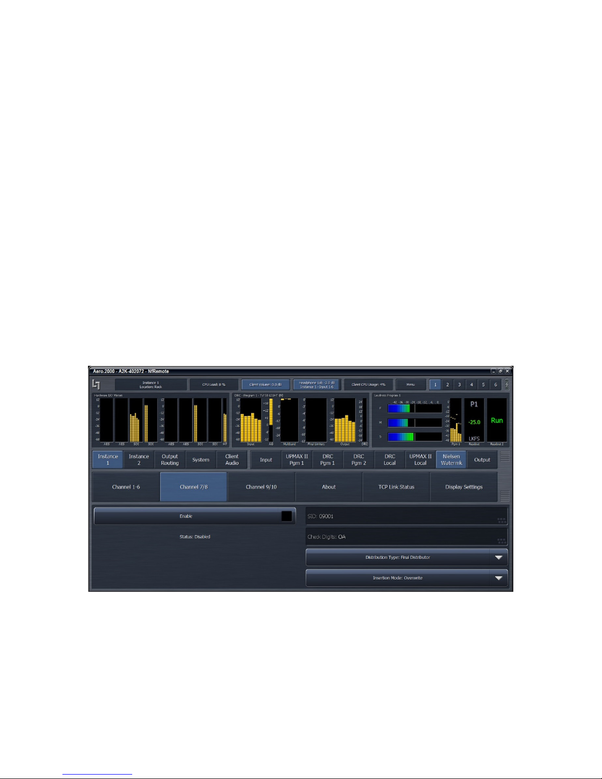
AERO.2000 User Guide July 2016
Instance x > Source > Input 9/10.
Any AES or SDI input source can be chosen from the drop-down.
This DRC Local UpMAX upmixing processor is intended to work with a stereo audio source.
Upmax can be enabled or disabled manually, by GPI or by IP command. Setup parameters for
the upmix (Main Settings and Adjust) can be set, saved and recalled, independently of the DRC
1 upmix. UpMAX local is only available in AMX5.1 Instances.
6.15
6.15 Nielsen
6.156.15
Nielsen encoding is licensed per AMX Instance. If the Nielsen encoding option is licensed in an
processing Instance then there is a Nielsen encoder for each of the Instance’s 3 DRC outputs.
Each Nielsen encoder can use the same or different Nielsen codes. Each Nielsen code requires
Check Digits to enable the channel encoder. Only Nielsen can provide an AERO.2000 user with
the Check Digits.
The Nielsen configuration screen is shown in Figure 6-16.
Nielsen Watermark
NielsenNielsen
Watermark
WatermarkWatermark
L16/1/18039
The tabs for each DRC output can be seen in Figure 7-16. Click Channel 1-6, Channel 7/8 and
Chanel 9/10 to configure Nielsen codes for each output.
Nielsen encoding can be enabled and disabled for each of the 3 outputs. Please note that
Nielsen encoding must be disabled to make changes to the SID or Check Digits.
©2016 LINEAR ACOUSTIC INC. THE TELOS ALLIANCE. ALL RIGHTS RESERVED
Figure 6-16 Nielsen configuration
Page 49
Page 64
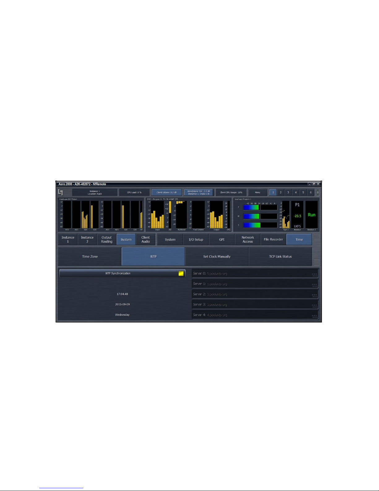
AERO.2000 User Guide July 2016
6.16
6.16 NTP Setup
6.166.16
A reliable time standard is required for time stamping loudness logs and for Nielsen encoding.
The AERO.2000 can synchronize its internal clock to a network time server using NTP. All three
of the time setup menus; Time Zone; NTP; and Set Clock Manually; can be seen in Figure 6-17,
below.
NTP Setup
NTP SetupNTP Setup
1. Start by setting your time zone. Time settings should be done before the unit is placed
on-line. Setting the Time Zone requires a reboot of the AERO.2000!
2. Next disable NTP and set the time and date manually in the Set Clock Manually menu.
3. When NTP Synchronization is disabled it allows changes to be made in the NTP server
addresses. Enter the network NTP server addresses and enable NTP.
L16/1/18039
To verify NTP operation:
1. Click on NTP tab and Disable NTP Synchronization.
2. Click on Set Clock Manually and change the time by a few hours.
3. Go back to NTP tab and see that the time is incorrect.
4. Enable NTP Synchronization.
©2016 LINEAR ACOUSTIC INC. THE TELOS ALLIANCE. ALL RIGHTS RESERVED
Figure 6-17 NTP configuration
Page 50
Page 65
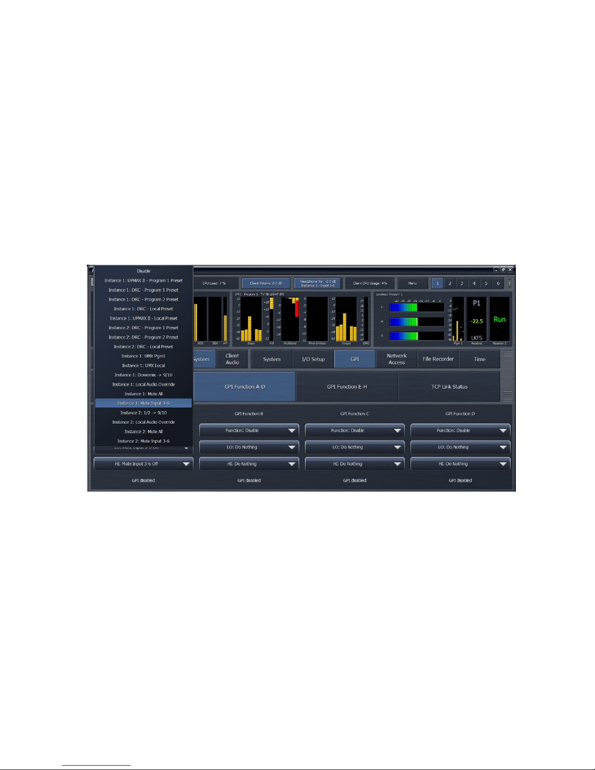
AERO.2000 User Guide July 2016
5. Time should jump to correct current time. IF it does not then the NTP server(s) are not
reachable by the AERO.
6.17
6.17 GPI Setup
6.176.17
Follow the path System > GPI > GPI. Here there is a GPI enable/disable ‘switch’. Click so that
the indicator is dark indicating that the GPIs are disabled. The GPIs must be disabled to make
changes to any GPI.
Click on: System > GPI > GPI Function A-D. This will display the configuration for the first 4 GPIs.
Click GPI Function E-H for the remaining 4 GPIs.
Figure 6-18 shows the list of available functions open for GPI A.
GPI Setup
GPI SetupGPI Setup
L16/1/18039
In Figure 6-18 Instance 1: Mute Input 3-6 is highlighted. This function switches the Dolby Digital
(or Dolby Digital Plus) encoder to stereo mode when a stereo source is on input channels 1/2.
Each GPI can be set up with specific functions for open and pulled to ground states as shown in
Figure 6-19. GPI Function B is shown to illustrate the choices available for each condition of the
GPI.
©2016 LINEAR ACOUSTIC INC. THE TELOS ALLIANCE. ALL RIGHTS RESERVED
Figure 6-18 GPI configuration
Page 51
Page 66
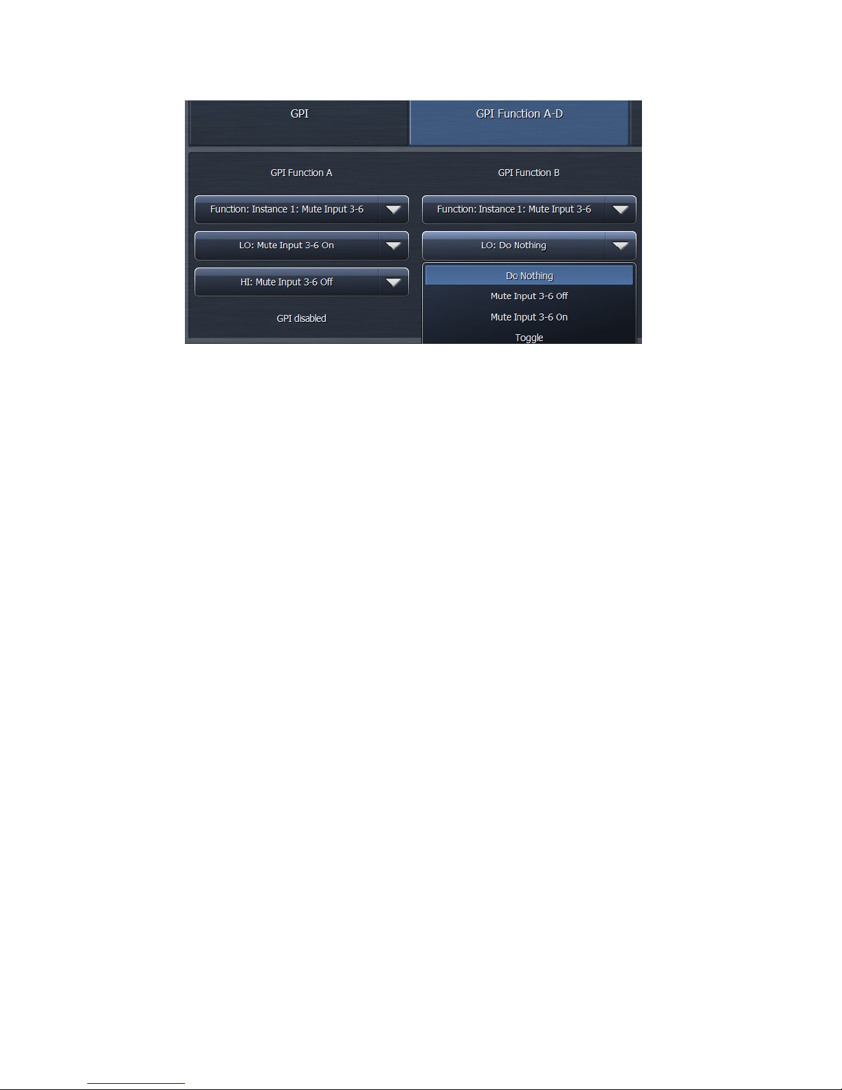
AERO.2000 User Guide July 2016
6.18
6.18 General Notes
6.186.18
Below are several notes about using NfRemote.
General Notes About NfRemote
General NotesGeneral Notes
• Multiple computers can connect to the same AERO.10/100/2000 unit simultaneously.
Figure 6-19 GPI detail
About NfRemote
About NfRemoteAbout NfRemote
L16/1/18039
• One computer can connect to multiple AERO.10/100/2000/ units simultaneously by
running NfRemote multiple times on the same PC. This is a handy feature for
monitoring or adjusting main and backup units at the same facility or monitoring and/or
configuring units assigned to multiple channels or different stations.
• Each instance of a remote connection requires some horsepower from AERO.2000’s
CPU. Observe the CPU load and do not exceed 80% even for short periods of time.
• Tasks that require significant CPU resources include; using multiple instances of the
oscilloscope and streaming client audio to multiple remote computers. Although it is
highly unlikely that your AERO.2000 CPU would run out of resources, even in a fully
configured unit addressed from several remote computers, it is important to monitor
the AERO’s CPU load! Fortunately, the CPU percentage meter will warn you when
resources begin to run low.
• The available bandwidth on the local network determines how robust the remote
connection will be.
• The remote software measures available network resources during the initial handshake
with AERO.2000. If bandwidth is marginal, some patch points may be unavailable for
remote monitoring of the oscilloscope and spectrum analyzer.
©2016 LINEAR ACOUSTIC INC. THE TELOS ALLIANCE. ALL RIGHTS RESERVED
Page 52
Page 67

AERO.2000 User Guide July 2016
L16/1/18039
• The quality of the client audio streamed to a remote computer will be adjusted to best
match current network resources.
• The latest version of NfRemote is always included with any software or firmware
upgrade. Only the latest version of NfRemote will provide all of the interface features
that the latest software and firmware provide. Always update all copies of NfRemote
with the latest version after an upgrade. Newer versions of NfRemote are compatible
with older software revisions of AERO.10/100/2000.
©2016 LINEAR ACOUSTIC INC. THE TELOS ALLIANCE. ALL RIGHTS RESERVED
Page 53
Page 68

AERO.2000 User Guide July 2016
7777 Configuration Check List
Configuration Check List
Configuration Check ListConfiguration Check List
Here is a list, in order, of what needs to be done to configure an AERO.2000 for use in a typical
television broadcast facility. This check list starts with the assumption that there is already a
connection between an MS Windows PC (or laptop, tablet, etc.) running NfRemote and the
AERO.2000.
1. System > Time > Time Zone. Set Time Zone and select Yes (in pop-up) to reboot.
2. System > Time > Set Time Manually. Set current date and time.
3. System > Time > NTP. Click NTP Off (indicator black). Enter NTP server addresses.
Select NTP On.
4. System > I/O Setup > SDI Embedding. Set SDI embedding On and select audio sources
for each embedded output pair.
5. If embedding is set to Off, then: System > I/O Setup > Hardware I/O Setup. Set
reference signal
6. System > I/O Setup > SDI Video Delay. Set to 180 ms if there is no internal Dolby
encoding. Set to 244 ms if Dolby encoding will be done in the AERO.2000
7. Instance 1 > Input > Source. Select the input source for each DRC input pair in Instance
1.
8. If an AMX5.1 Instance will be used for stereo sources full time, then:
Instance 1 > Input > Input Switches. Select Mute Input 3-6
9. Output Routing > AES/SDI Outputs > SDI Outputs. Select the DRC outputs that will be
embedded in each SDI output channel pair.
10. Output Routing > AES/SDI Outputs > AES Outputs. Select the DRC outputs that will be
embedded in each AES digital audio output pair.
11. Instance 1 > UpMAX II Program 1 > Load Preset. If upmixing will be used select a preset.
Instance 1 > UpMAX II Program 1 > Main Settings. Click Upmix Enable.
Instance 1 > UpMAX II Program 1 > Main Settings. Set Automode = Auto for mixed
source content or On if all source content is stereo and it will all be upmixed.
L16/1/18039
©2016 LINEAR ACOUSTIC INC. THE TELOS ALLIANCE. ALL RIGHTS RESERVED
Page 54
Page 69

AERO.2000 User Guide July 2016
L16/1/18039
12. Instance 1 > DRC-Program 1 > Load Preset. Select and load a loudness control preset.
Instance 1 > DRC-Program 1 > Final. Set Final Output so that average LKFS output on
Program 1 loudness meter is on target. (usually -24 dB LKFS or -23 dB LUFS)
13. Instance 1 > DRC-Program 2 > Load Preset. Select and load a loudness control preset.
Instance 1 > DRC-Program 2 > Final. Set Final Output so that average LKFS output on
Program 2 loudness meter is on target. (usually -24 dB LKFS or -23 dB LUFS)
14. If the program on DRC-Program 2 is SAP on a single channel of the input pair then 7/8
Input Source can be selected to take 7 only, or 8 only:
Instance 1 > Output > 7/8 Input Source. Select 7 or 8.
15. If the program on DRC-Program 2 is SAP and automatic replacement of missing SAP with
a main channel downmix is desired, then:
Instance 1 > Output > 7/8 Output. Set 7/8 Output Mode = Auto Downmix. Adjustments
of downmix output level and crossfades and hold-off for SAP replacement by downmix
and Downmix by SAP are provided.
16. If a full time downmix is wanted on the DRC 7/8 Output, then:
Instance 1 > Output > 7/8 Output. Set 7/8 Output Mode = Main Downmix.
17. Instance 1 > DRC-Local > Load Preset. Select and load a loudness control preset.
Instance 1 > DRC-Local > Final. Set Final Output so that average LKFS output on Program
Local loudness meter is on target. (usually -24 dB LKFS or -23 dB LUFS)
18. If the program on DRC-Local is SAP on a single channel of the input pair then 9/10 Input
Source can be selected to take 7 only, or 8 only:
Instance 1 > Output > 9/10 Input Source. Select 7 or 8.
19. If the program on DRC-Local is SAP and automatic replacement of missing SAP with a
main channel downmix is desired, then:
Instance 1 > Output > 9/10 Output. Set 9/10 Output Mode = Auto Downmix.
Adjustments of downmix output level and crossfades and hold-off for SAP replacement
by downmix and Downmix by SAP are provided.
20. If a full time downmix is wanted on the DRC 9/10 Output, then:
Instance 1 > Output > 9/10 Output. Set 9/10 Output Mode = Main Downmix.
21. If the DRC-Local input will be used for main or DRC-Program 2 program replacement, or
for EAS or for local emergency audio override, the configuration is found here:
Instance 1 > Output > Local
©2016 LINEAR ACOUSTIC INC. THE TELOS ALLIANCE. ALL RIGHTS RESERVED
Page 55
Page 70

AERO.2000 User Guide July 2016
L16/1/18039
22. If DRC Local will be used for main program replacement and upmixing of the local input
is desired:
Instance 1 > UpMAX II Local > Load Preset
Instance 1 > UpMAX II Local > Main Settings
Instance 1 > UpMAX II Local > Adjust
23. If Nielsen encoding option is included the setup is found here:
Instance 1 > Nielsen > Channel 1-6, and Channel 7/8 and Channel 9/10.
Note: Only Nielsen can provide the Check Digits necessary to enable the encoder for
each unique SID.
24. Instance1 > Output > Target. This sets the reference level of the loudness meters for
each DRC output. If Dolby encoding is included Target also sets the Dolby dialnorm
metadata value.
25. Instance1 > Output > Dolby Digital Plus Encoder. If the Dolby encoding option is
included, then the settings for Dolby Digital and Dolby Digital + are set in this menu.
26. Instance1 > (any sub-menu) > Display Settings. Any of the available metering can be
configured from this menu. There are 6 instance screen recall presets available. These
are buttons 1 to 6 in the upper right side of the NfRemote display.
27. Instance1 > Output > Loudness Meter. The loudness meter bar-graph displays and
digital readout displays for each DRC output are configured here.
28. Instance1 > Output > Delay. If video delay is set to the nearest full video frame greater
than the audio latency of the AERO.2000 then additional audio delay can be set here for
proper lipsync. LPCM outputs can also be delayed separately from Dolby encoded
output delay to allow both to have proper lip synch at the same time.
29. Client Audio > Client Audio Output > Patch Point. Hardware inputs and outputs and
many other “patch points” within the AERO.2000 can be monitored on a remote PC
using NfRemote. A high quality soundcard and a stereo, or surround, playback system
allows monitoring of the audio while configuration changes are made. NfRemote
provides EQ and other processing to create accurate stereo and surround monitoring
environments wherever the PC is located. If the network connection supports it then
high quality audio streaming is provided.
30. If there is a second Instance, then steps 7 through 28 are repeated for the additional
instance.
©2016 LINEAR ACOUSTIC INC. THE TELOS ALLIANCE. ALL RIGHTS RESERVED
Page 56
Page 71
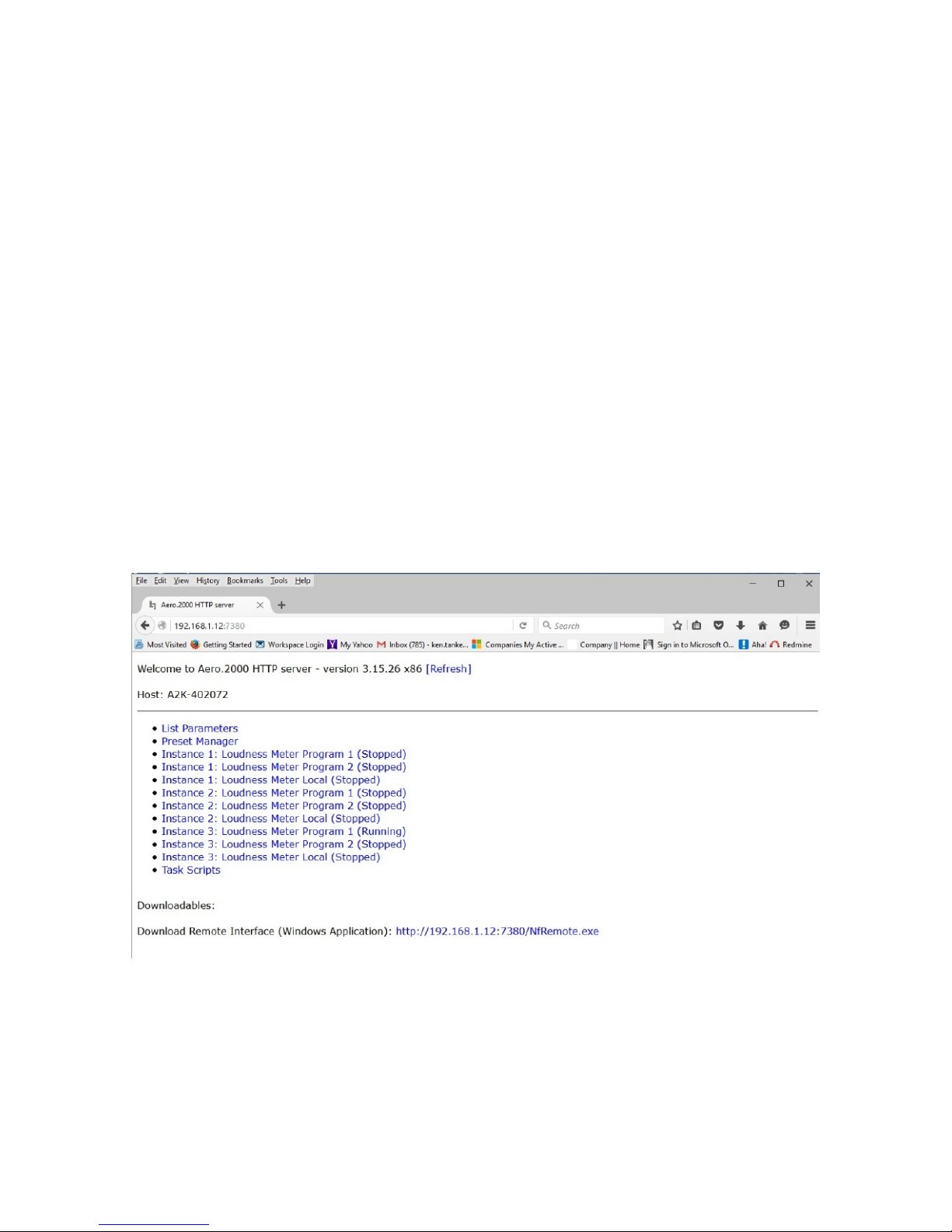
AERO.2000 User Guide July 2016
8888 Logs and
Logs and Control Scripts
Logs and Logs and
Your PC ’s IP address must appear in the AERO.2000’s HTTP white list in order to have access to
the built in HPPT server. If this has not been done yet refer to section 5.5.
The script feature is new to version 3.15.26. A script is a series of parameter change commands
that can be named and saved as a Task. These tasks can then be assigned to any of the
available GPIs. Any command that is available through the AERO.2000 HTTP server, as an IP
based command, can be placed in a script and saved as a task. Now GPI control can be used to
change any parameters, in any combination. The possibilities are nearly infinite.
8.1
8.1 HTTP Server Access
HTTP Server Access
8.18.1
HTTP Server AccessHTTP Server Access
To access the AERO.2000’s HTTP server use any browser and enter the AERO’s IP address and
the HTTP server port, 7380. For example: 192.168.1.12:7380
MS IE requires the entry of: http://192.168.1.12:7380.
The HTTP server page that will open is shown in Figure 8-1.
Control Scripts
Control ScriptsControl Scripts
L16/1/18039
©2016 LINEAR ACOUSTIC INC. THE TELOS ALLIANCE. ALL RIGHTS RESERVED
Figure 8-1 HTTP Server Home Page
Page 57
Page 72
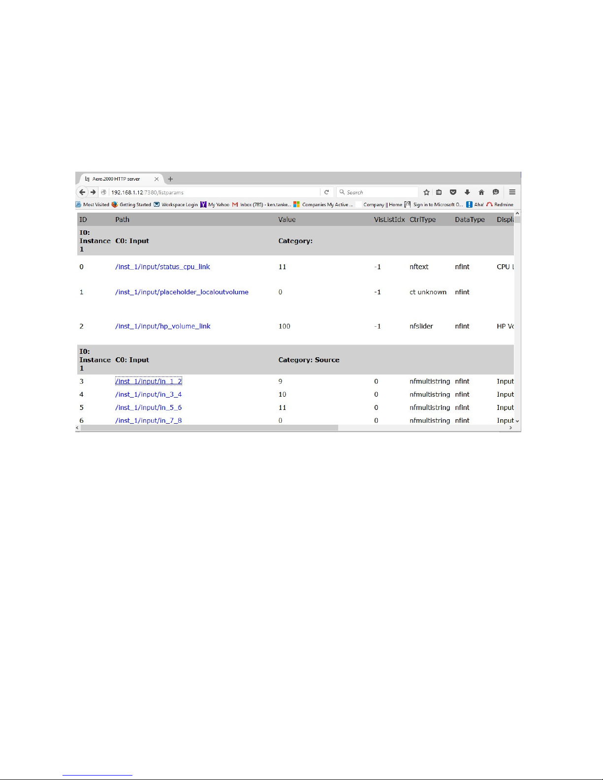
AERO.2000 User Guide July 2016
8.2
8.2 HTTP
HTTP List Parameters
8.28.2
HTTP HTTP
List Parameters shows every parameter in the AERO.2000 that can be controlled via the HTTP
server and a network command. In Figure 8-2 is the screen you see after clicking List
Parameters. Scroll up and down to move through the parameters. You can also use the Edit
tool in your browser to open the Find dialogue box to search for parameters.
List Parameters
List ParametersList Parameters
L16/1/18039
Figure 8-2 HTTP List Parameters
Under Category: Source the first command is /inst_1/input/in_1_2
• The next column shows the current value and it is 9.
• Click on: /inst_1/input/In_1_2
• In the screen that opens you see the command in the browser address line.
• The first line on the browser page shows the current value of the parameter.
• Below this is the command name followed by all of the possible parameter selections,
and the command syntax.
• Value 9 = SDI 1/2. This means that the value 9 for routes SDI 1/2 to Instance 1, Input
1/2.
©2016 LINEAR ACOUSTIC INC. THE TELOS ALLIANCE. ALL RIGHTS RESERVED
Page 58
Page 73

AERO.2000 User Guide July 2016
• See Figure 8-3.
L16/1/18039
©2016 LINEAR ACOUSTIC INC. THE TELOS ALLIANCE. ALL RIGHTS RESERVED
Page 59
Page 74
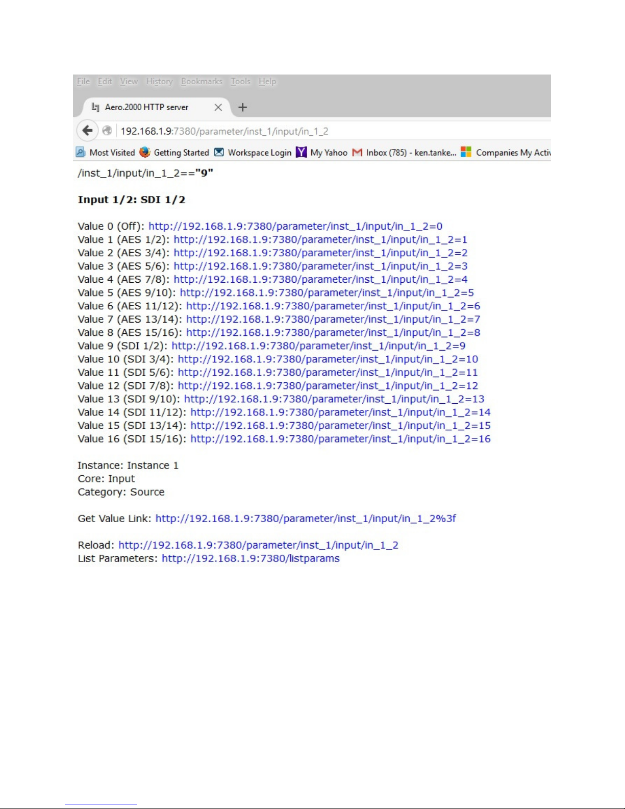
AERO.2000 User Guide July 2016
L16/1/18039
Figure 8-3 Input 1/2 Source HTTP command
The source for Instance 1, Input 1/2 can be changed manually.
• Find the Parameter Value for SDI 11/12 in the list if commands.
• The parameter value is 14
• Click on the command 192.168.1.12/parameters/inst_1/input/in_1_2 = 14
©2016 LINEAR ACOUSTIC INC. THE TELOS ALLIANCE. ALL RIGHTS RESERVED
Page 60
Page 75
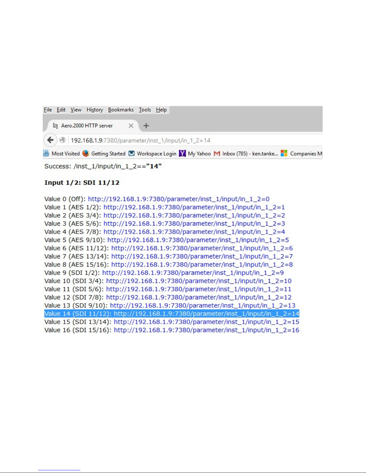
AERO.2000 User Guide July 2016
L16/1/18039
• The source routed to Instance 1, Input 1/2 is changed instantly.
• The command now appears in the browser address line.
• See Figure 8-4
Figure 8-4 Command to route source SDI 11/12 to Instance 1, Input 1/2
A traffic or facility automation system can send multiple commands, one after the other, in
order to accomplish any desired changes.
Any number of commands can be placed in a script. The script can be named and the named
scripts appear in the AERO GPI menu as Tasks. Tasks can be assigned to GPIs allowing any
combination of parameter changes to be accomplished using simple GPI commands.
©2016 LINEAR ACOUSTIC INC. THE TELOS ALLIANCE. ALL RIGHTS RESERVED
Page 61
Page 76
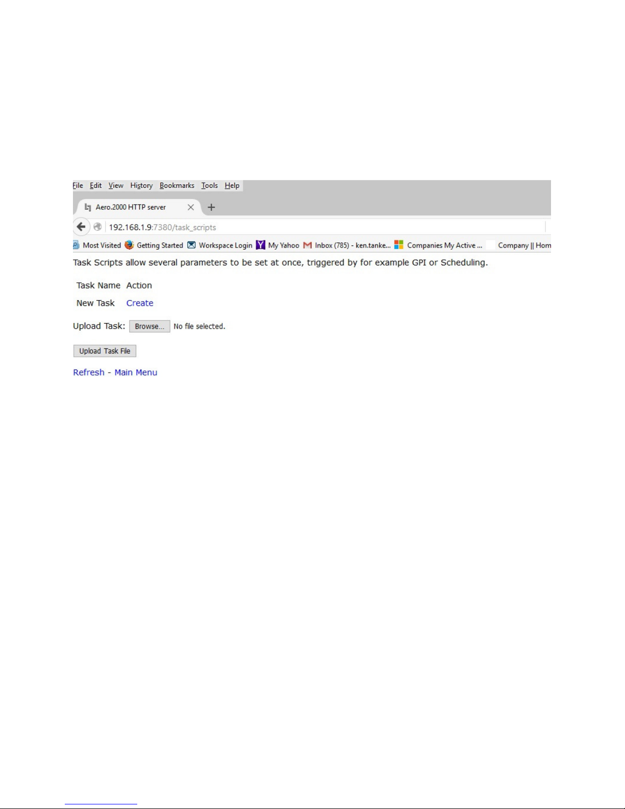
AERO.2000 User Guide July 2016
8.3
8.3 Creating a Script
Creating a Script
8.38.3
Creating a ScriptCreating a Script
• go to the HTTP main page and click Task Scripts.
• See Figure 8-4
• Click on Create
L16/1/18039
Figure 8-4 Creating Scripts
A new screen opens with a sample script.
See Figure 8-5, below.
©2016 LINEAR ACOUSTIC INC. THE TELOS ALLIANCE. ALL RIGHTS RESERVED
Page 62
Page 77
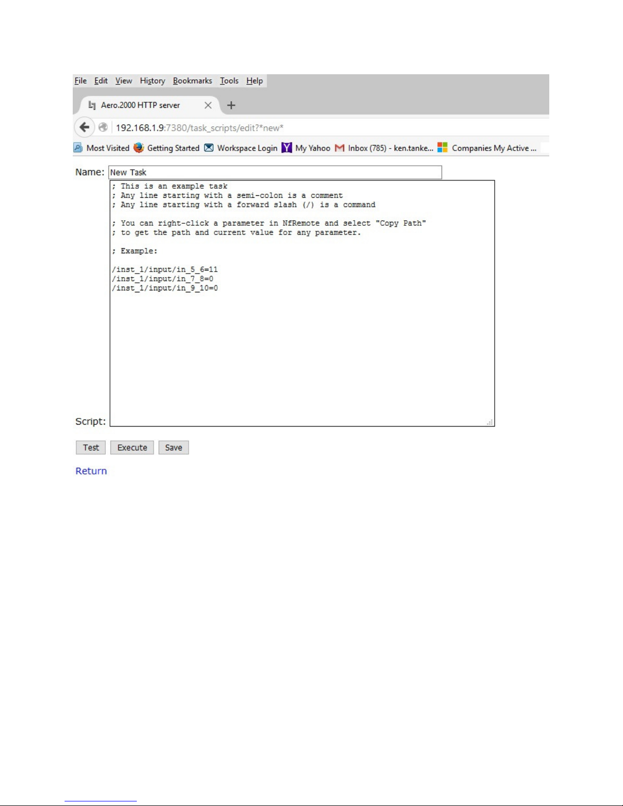
AERO.2000 User Guide July 2016
L16/1/18039
Figure 8-5 Sample script
Type in a name for the script. We recommend that the name is descriptive to make selecting
one script, from a number of saved scripts, easy.
Below two scripts will be described.
1. Inst1-SDI-1-2-to-In-1-2-Stereo
a. Route SDI audio source pair 1/2 to Instance 1, Input 1/2
b. Mute 3-6 will mute Instance 1, Inputs 3, 4, 5 and 6
c. set the Dolby AC3 encoder to 2.0 mode
2. Inst1-SDI-5-10-to -In-1-6-Surround
a. Route SDI audio source pairs 3, 4, 5 to Instance 1, Input 1/2, 3/4, 5/6.
b. Unmute channels 3-6
©2016 LINEAR ACOUSTIC INC. THE TELOS ALLIANCE. ALL RIGHTS RESERVED
Page 63
Page 78
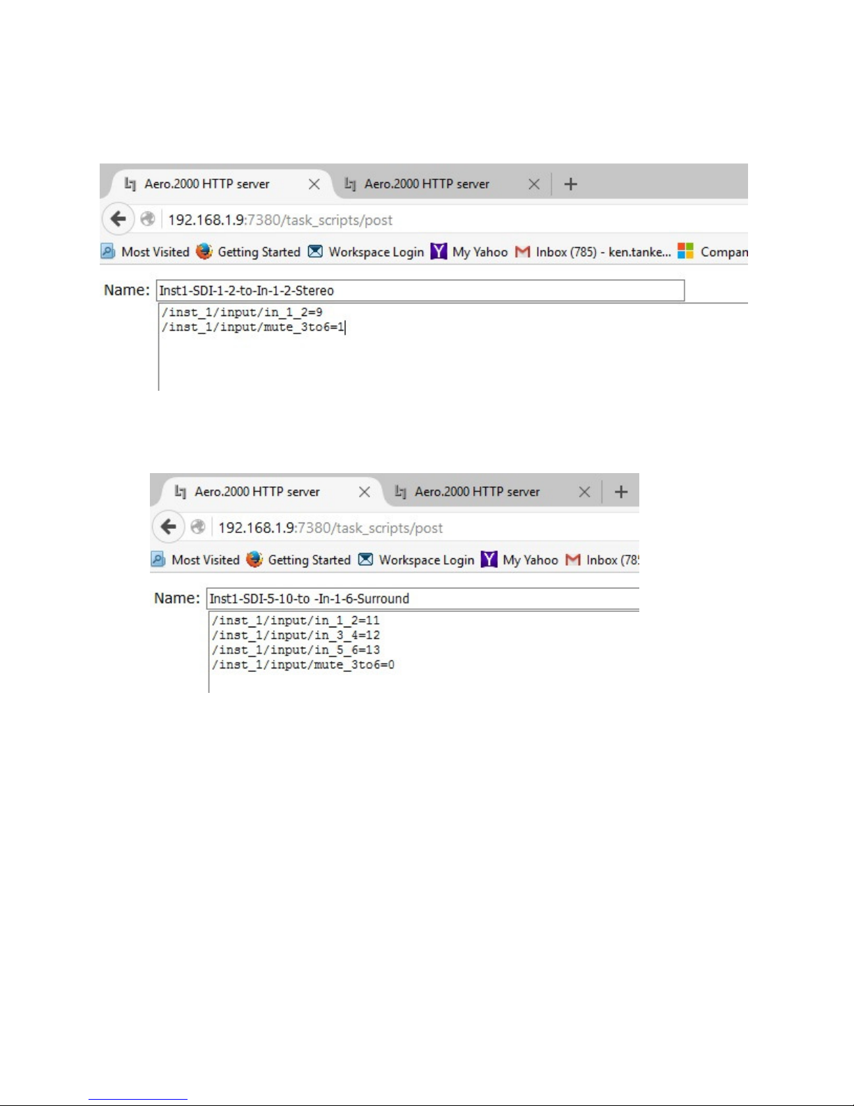
AERO.2000 User Guide July 2016
L16/1/18039
c. Set Dolby AC3 encoder to 5.1 mode
The first script, for a stereo program on SDI 1/2 is shown in Figure 8-6.
Figure 8-6 Script for stereo source with stereo Dolby AC3 encoding
The second script, for 5.1 surround on SDI 5/6, 7/8 and 9/10 is shown in Figure 8-7
Figure 8-6 Script for surround source and surround Dolby AC3 encoding
Please note that a second HTTP tab is also open in the browser in Figure 8-6. This will allow the
parameters to be searched and the needed commands cut and pasted into the open script on
the first browser tab.
If NfRemote is open a Right-Click on any control will open a copy dialog box. Click Copy Path
and then paste into the script. The result will look like this:
/inst_1/input/mute_3to6=1
This is the command to mute Inputs 3-6 and change the Dolby AC3 encoder to 2.0 mode.
See Figure 8-7 below.
©2016 LINEAR ACOUSTIC INC. THE TELOS ALLIANCE. ALL RIGHTS RESERVED
Page 64
Page 79
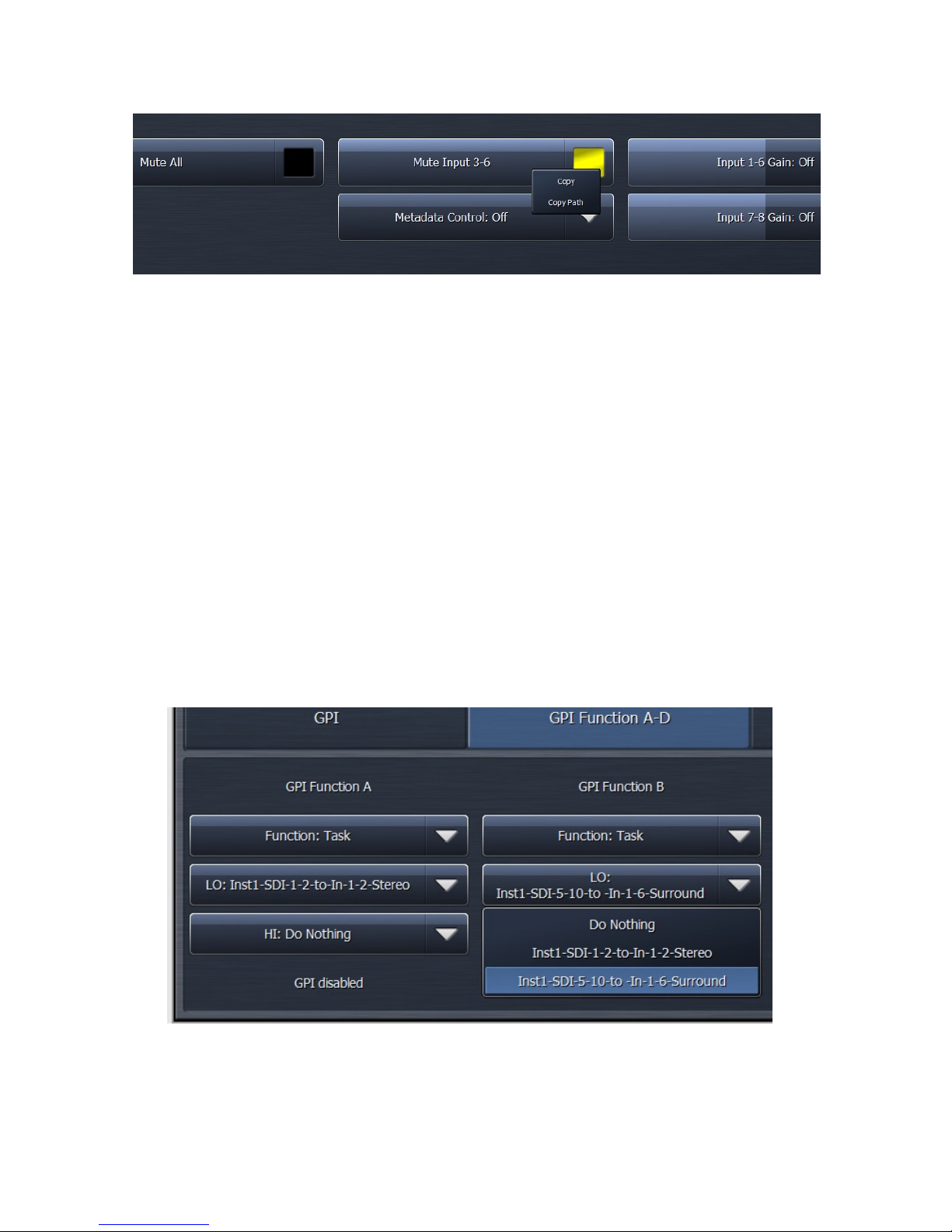
AERO.2000 User Guide July 2016
L16/1/18039
Figure 8-7 Copying the script command for Mute Input 3-6
After creating and saving a script it becomes a Task. To assign Tasks to GPIs:
1. Navigate to System > GPI > GPI Function A-D (or E-H)
2. Click on GPI Function A and select Task from the drop down box
3. Click Lo and select a script to run when GPI A is pulled low.
4. Click Hi and select Do Nothing
5. Click on GPI Function B and select Task from the drop down box
6. Function Click Lo and select a script to run when GPI A is pulled low.
7. Click Hi and select Do Nothing
8. Remember to Enable GPIs for the GPIs to work
See Figure 8-8.
1. GPI A will run the script: Inst1-SDI-1-2-to-In-1-2-Stereo
2. GPI B will run the script: Inst1-SDI-5-10-to -In-1-6-Surround
3.
Figure 8-8 Assign tasks to GPIs
©2016 LINEAR ACOUSTIC INC. THE TELOS ALLIANCE. ALL RIGHTS RESERVED
Page 65
Page 80
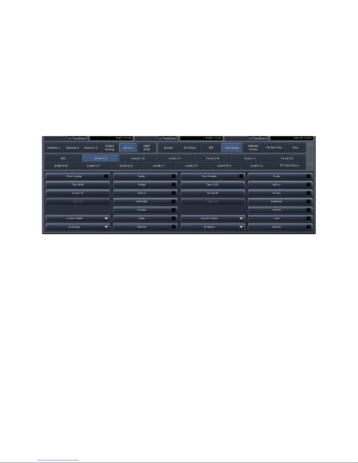
AERO.2000 User Guide July 2016
8.4
8.4 AERO Scheduling
AERO Scheduling
8.48.4
AERO SchedulingAERO Scheduling
Another new feature in latest update to AERO.2000 is an internal automation system. Any
command in the GPI menu, and any Task, can be run according to a day-of-the-week, hour-ofthe-day, internal scheduling application. The scheduling is part of the NfRemote GUI and can
be found by navigating to:
System > Scheduling > Event x-y
See Figure 8-9.
L16/1/18039
Figure 8-9 Event Scheduler
Two events are shown on each of 13 screens named Event A-B to Event Y-Z.
1. Each event can be scheduled to the hour/minute/second and the day of the week.
2. An event can be scheduled to occur at the assigned time on multiple days.
3. Assignment of the event is done in the same way as a GPI is assigned.
The stereo and 5.1 surround switching Tasks, created in section 8.3, are used in the next
example.
Figure 8-10 shows the change to stereo occurring every weekday at 11:29:59 PM. The
scheduler works in 24-hour time to avoid errors. The time is shown as 23:59:59. The scheduled
event is not enabled yet and can still be modified. All selections are available.
In the next example, shown in Figure 8-11, the AERO is switched to 5.1 surround mode every
weekday at 5:59:59 AM. In this figure the event is enabled and al selections are grayed out
because they cannot be modified while the event is enabled.
©2016 LINEAR ACOUSTIC INC. THE TELOS ALLIANCE. ALL RIGHTS RESERVED
Page 66
Page 81
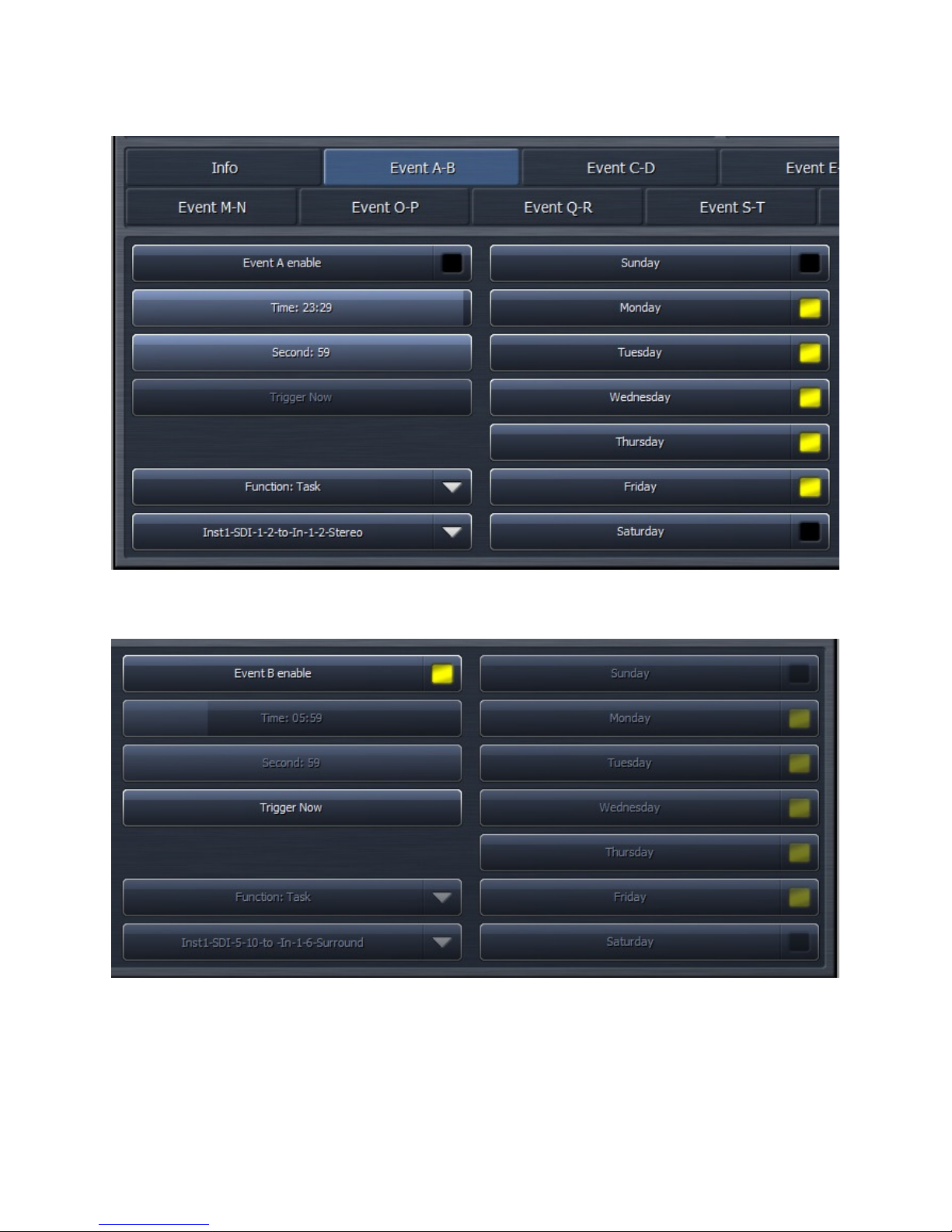
AERO.2000 User Guide July 2016
L16/1/18039
Figure 8-10 Internal Scheduler, Event A
Figure 8-11 Internal Scheduler, Event B, enabled
©2016 LINEAR ACOUSTIC INC. THE TELOS ALLIANCE. ALL RIGHTS RESERVED
Page 67
Page 82

AERO.2000 User Guide July 2016
8.5
8.5 Loudness Logs
Loudness Logs
8.58.5
Loudness LogsLoudness Logs
The AERO.2000 creates and stores logs for each program output. The logs can be found in the
unit’s HTTP server. Log scan be viewed and moved manually through the HTTP server interface
or using standard HTTP Server commands.
1. All logs are in .csv format
a. To see the full date and time in MS Excel the date column must be formatted
b. Use Custom format in an MX Excel column
c. dd/mm/yyyy h/mm/sss
2. There are 4 logs automatically created for each program output.
a. These logs are continually created in a first-in-first-out basis (FIFO).
b. These logs record the following measurements every second:
i. 3 second 10 second and 30 second integrated LKFS values
ii. True Peak
iii. Dialnorm
iv. acmod metadata
c. these three logs are 24 hours, 48 hours and 7 days long
d. Each log is longer than the specified duration in order to allow time to remove
the log with missing any data
3. The fourth log:
a. records 400ms LKFS measurements every 100 ms.
b. The log is a 70 minute long FIFO
c. These values allow any ITU-R BS. 1770-3 measurements to be calculated over
any duration of time.
4. There is a 5th manually controlled log.
a. This log allows an operator to start and stop a log manually
b. The manual log can be viewed in the HTTP server or downloaded for later
viewing
The logs can be found on the main HTTP page. See Figure 8-12, below.
There are links here for the logs of each program output of each Instance.
Notice that after each log is the word (Stopped). This is the status of the manually operated
user log.
L16/1/18039
©2016 LINEAR ACOUSTIC INC. THE TELOS ALLIANCE. ALL RIGHTS RESERVED
Page 68
Page 83
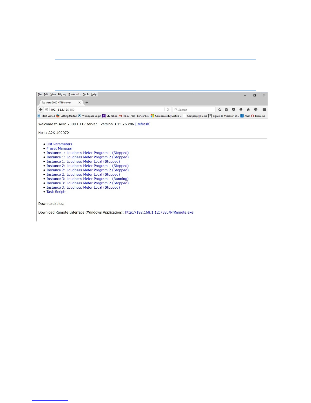
AERO.2000 User Guide July 2016
NOTE!
The 4 automatic LKFS logs described above are always running. None of the
settings for the metering displays or any user commands will stop or alter the
automatic LKFS logging.
L16/1/18039
Figure 8-12 Loudness Logs
Click on Instance 1: Loudness Meter Program 1 (stopped). The following screen appears:
©2016 LINEAR ACOUSTIC INC. THE TELOS ALLIANCE. ALL RIGHTS RESERVED
Page 69
Page 84
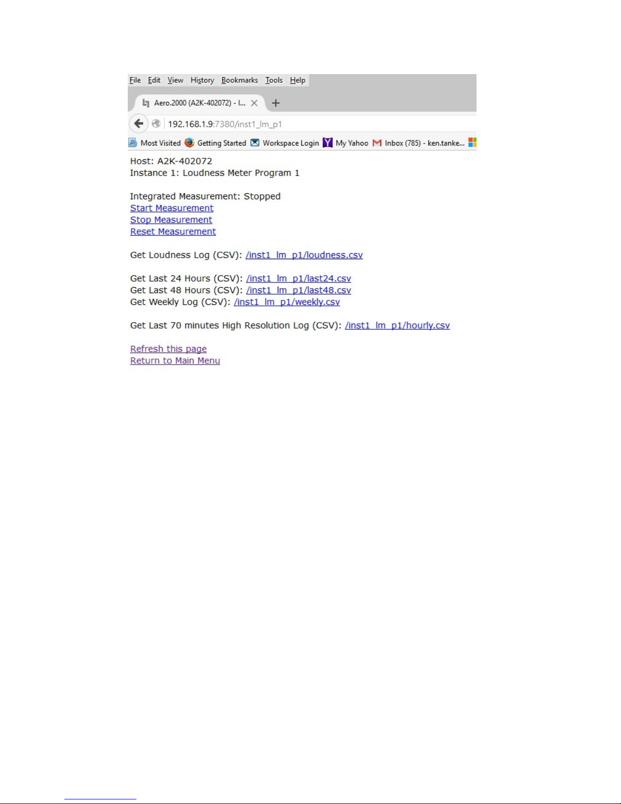
AERO.2000 User Guide July 2016
L16/1/18039
Figure 8-13 Logging screen for Instance 1, Meter Program 1
Double-Click any of the .csv links to open the log file in the browser.
Right-Click and select Save Link As to save the file to the local PC or on a network location.
A sample of the raw log data for the 24 hr., 48 hr., and the 7 day log is shown in Figure 8-14.
©2016 LINEAR ACOUSTIC INC. THE TELOS ALLIANCE. ALL RIGHTS RESERVED
Page 70
Page 85
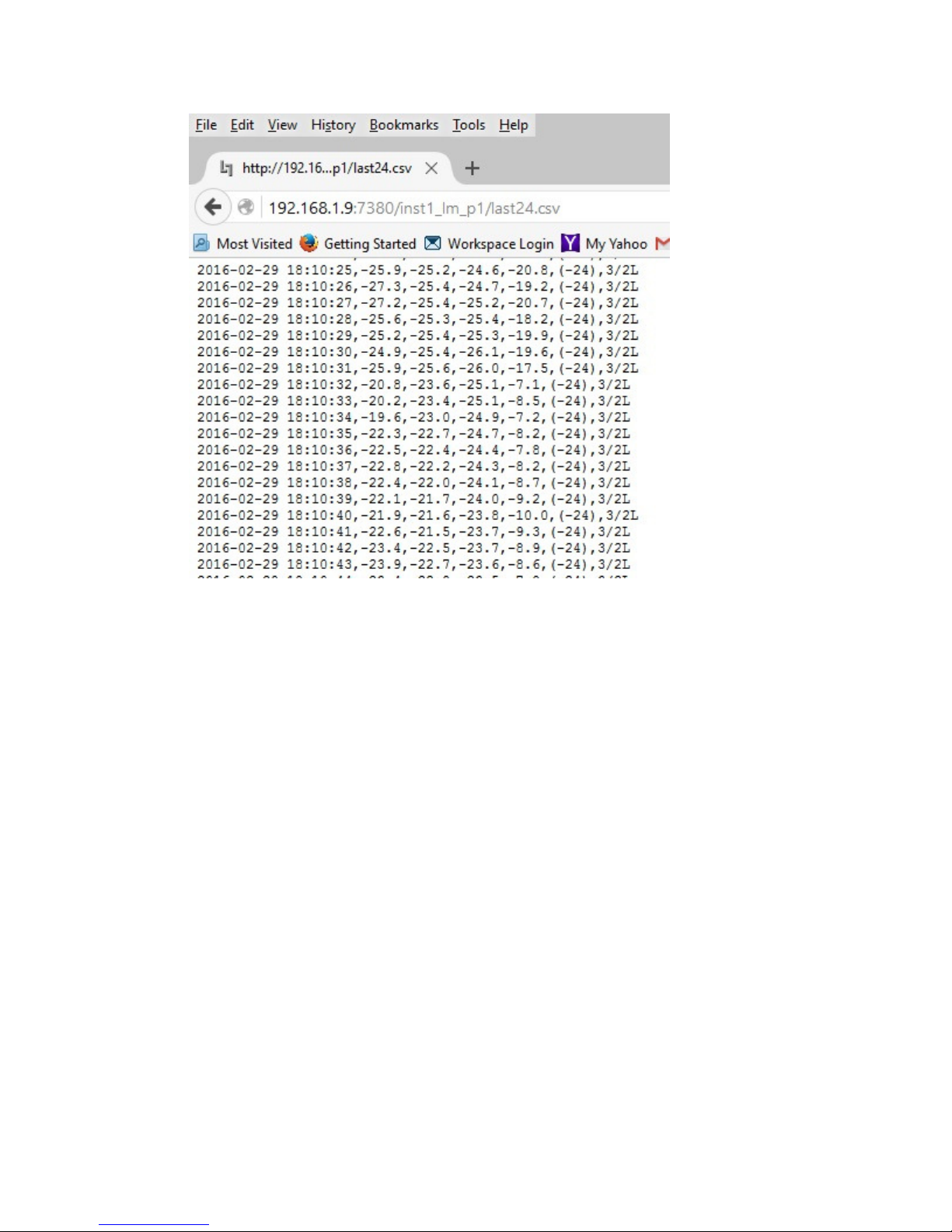
AERO.2000 User Guide July 2016
L16/1/18039
Figure 8-14 Raw Log data
Any of the logs can also be fetched using standard HTTP commands.
Users have written software that downloads the desired logs and saves them or uses them to
create a combined traffic log with running LKFS measurements.
The Start, Stop and Reset Measurement links are for the user controlled manual log.
/inst1_lm_p1/loudness.csv is the link to the log for this meter.
Right-Click the link and select Save Link As to save the file on the local PC or network.
©2016 LINEAR ACOUSTIC INC. THE TELOS ALLIANCE. ALL RIGHTS RESERVED
Page 71
Page 86

AERO.2000 User Guide July 2016
L16/1/18039
Note that at the bottom of manually controlled user log, below the running second
measurements, there are several values.
• ITU BS.1770 Integrated Ungated:
• ITU BS.1770-2 Integrated Gated:
• EBU R128 Integrated:
• EBU R128 Integrated:
• Maximum Peak: dBTP
• EBU R128 Loudness Range:
©2016 LINEAR ACOUSTIC INC. THE TELOS ALLIANCE. ALL RIGHTS RESERVED
Page 72
Page 87

AERO.2000 User Guide July 2016
9999 Special
Special Features
Special Special
9.1
9.1 SAP (secondary audio program) Handling
SAP (secondary audio program) Handling
9.19.1
SAP (secondary audio program) HandlingSAP (secondary audio program) Handling
In the U.S. many stations have SAP audio for one or more programs. DVS (descriptive video
service) is also a requirement. Many networks deliver SAP programming as a single channel of
an embedded pair. AERO.2000 makes broadcasting SAP easy.
• Instance 1 > Input > Source. Select the SAP source pair, typically 7/8 to Input 7/8. This
places SAP audio on the DRC Program 2 input.
• Instance 1 > Output > Output 7/8 > 7/8 Input source. Select 7 Only from the drop down.
SAP/DVS audio on channel 7 will made a dual mono pair and loudness controlled.
• SAP/DVS is typically not present for all programs. In order to maintain audio on the SAP
channel a loudness controlled downmix of Program 1 (Or simply the stereo audio of
Program 1) can be used to automatically replace SAP when there is no SAP source. The
assures that programs, promos, commercials and any content that does not have SAP
audio will have the main program (Program 1) audio on the SAP channel instead of
silence.
• Instance 1 > Output > Output 7/8 > 7/8 Output Mode. Set Output Mode to Auto
Downmix. Additional parameters in this menu permit the user to adjust the hold-off
time before SAP is replaced and how fast the downmix is replaced by SAP when it
returns.
• The SAP source audio can, alternately, be applied to DRC 9/10
• Instance 1 > Input > Source. Select the SAP source pair, typically 7/8 to Input 9/10. This
places SAP audio on the DRC Local input. Follow the steps above in the Output 9/10
menu:
Instance 1 > Output > Output 9/10
Features
FeaturesFeatures
L16/1/18039
9.2
9.2 Downmix Outputs
Downmix Outputs
9.29.2
Downmix OutputsDownmix Outputs
When using a 5.1 Instance (AMX5.1) two downmixes can be created. One uses the DRC
Program 2 output and one uses the DRC Local output. In some applications a downmix is
embedded in the SDI output for use downstream. For example, an SD output can be downconverted from the HD video, and the stereo downmix can be used for this.
©2016 LINEAR ACOUSTIC INC. THE TELOS ALLIANCE. ALL RIGHTS RESERVED
Page 73
Page 88

AERO.2000 User Guide July 2016
In other applications, like audio for in-house monitoring in control rooms or in-house audio
distribution a downmix can be routed an AES digital audio output. The same downmix output
can be routed simultaneously to an SDI embedded pair and an AES digital audio output.
Example of a configuration for a downmix output
1. Instance 1 > Output > Output 9/10.
2. Set downmix -> 9/10 to On for a full time downmix from the DRC 9/10 output.
3. There is also a downmix gain control in this menu.
When DRC Local 9/10 output is used for a fulltime downmix the DRC Local processor can still be
used for EAS, local emergency audio, or local program audio replacement of Program 1, OR
Program 2, OR Program 1 AND Program 2.
9.3
9.3 Local Audio Insert/Replace
Local Audio Insert/Replace
9.39.3
Local Audio Insert/ReplaceLocal Audio Insert/Replace
L16/1/18039
There are several applications for the audio replacement or override of main program audio.
• Local content may use a different embedded audio pair map than network or syndicated
programming.
• Network programming does not use upmixing but all local programming is upmixed.
• Insertion of emergency audio messages or signaling that replaces main audio and/or
SAP audio.
• Insertion of emergency audio messages or signaling that ducks main and/or SAP audio.
• Local audio programming that entirely replaces audio programming on the main and/or
SAP program(s).
Local audio configuration:
Instance 1 > Input > Source and select the audio source for the DRC Local input. The source can
be AES audio or an SDI embedded pair.
Instance 1 > Output > Local > 9/10 Input Mode. Select Local Mode for 9/10 input mode and all
the Local menu items becomes active.
Configure operation of the local audio override:
©2016 LINEAR ACOUSTIC INC. THE TELOS ALLIANCE. ALL RIGHTS RESERVED
Page 74
Page 89

AERO.2000 User Guide July 2016
Instance 1 > Output > Local > Destination chooses the program channel, Program 1, Program 2
or both that will be replaced or ducked behind the Local input.
Instance 1 > Output > Local > Local Audio Override drop down offers 4 selections:
• Off: no override or replace
• VOX: if there is audio on the DRC Local (9/10) input then the main program will
automatically be overridden. The Holdoff, Crossfade Speed and the duck level of the
program audio can all be adjusted in this menu. The main program can be muted or
ducked by n dB.
• Override: When in override mode local audio replaces program audio until Override is
switched Off.
• Replace: This is used to continuously replace program audio with local audio without
regard to whether or not there is audio on the 9/10 input.
• GPI or IP based commands can be used to switch override on and off.
L16/1/18039
9.4
9.4 Dolby Insert
Dolby Insert
9.49.4
Dolby Insert Dolby Insert
The Dolby encoder licensed to any Instance is internally connected so that DRC Program 1
output of that instance feeds the Dolby encoder. While this makes encoding the main program
audio easy there are circumstances when the connection needs to be broken.
Some broadcasters use a viewer ratings system encoder, which needs to be inserted after any
audio processing but before Dolby encoding.
To configure the Dolby insert proceed as follows for a 5.1 main program:
• Instance 1 > Output Routing > AES Outputs.
• Select AES Output 1/2 = Proc 1/2.
• Select AES Output 3/4 = Proc 3/4.
• Instance 1 > Output > Dolby Digital plus Encoder and Set Insert = On.
• Instance 1 > Inputs > Return A. Select AES 1/2
• Instance 1 > Inputs > Return B. Select AES ¾
©2016 LINEAR ACOUSTIC INC. THE TELOS ALLIANCE. ALL RIGHTS RESERVED
Page 75
Page 90

AERO.2000 User Guide July 2016
• Connect AERO.2000 AES outputs AES Outputs 1/2 and 3/4 to the external watermark
encoder inputs 1 and 2.
• Connect external watermark encoder outputs 1 and 2 to AERO.2000 AES inputs 1/2 and
3/4.
The viewer ratings encoder does not encode to the Ls or Rs channels so pairs 5/6 do not need
to be routed outside the AERO.2000. Processed channels 1/2 and 3/4 are routed through the
external encoder and directly to the Dolby encoder inputs through the Dolby Inserts. Return A
and B are the patch points to the Dolby Insert.
9.5
9.5 Dolby Encoding of Instance 1 SAP using Instance 2 Dolby
Dolby Encoding of Instance 1 SAP using Instance 2 Dolby
9.59.5
Dolby Encoding of Instance 1 SAP using Instance 2 Dolby Dolby Encoding of Instance 1 SAP using Instance 2 Dolby
Enco
Encoder
EncoEnco
There are some users that may want to insert a SAP program created in Instance 1 into the
stereo Dolby encoder in a stereo Instance 2. This is often the case when the user wants to
configure a SAP output that has auto replacement of missing SAP by a downmix of the main
channel. In the case of SAP configured on Instance 1, DRC Program 2 Follow the steps below.
1. Output Routing > AES/SDI routing > AES Outputs.
2. Select AES Out 1/2 and select Proc 7/8 from the drop down as the source. Processed
3. Instance 2 > Output > Dolby Digital Plus Encoder > Insert and select On.
4. Instance 2 > Input > Source > Return A and select AES 1/2 as the source.
5. Connect a physical unbalanced AES jumper between AERO.2000 AES 1/2 Out and AES
der
der der
SAP is now on AES output 1/2.
1/2 In.
L16/1/18039
9.6
9.6 Auto Replace of
Auto Replace of Stereo Program
9.69.6
Auto Replace of Auto Replace of
There is a feature of the 5.1 surround output channel. The most commonly used source pair
configuration for embedded SDI content is to place stereo programs on pair 1 (channels 1/2).
If content is mixed with 5.1 surround and stereo programs then the 5.1 surround content is
placed on pairs 1, 2 and 3 (Lf/Rf, C/LFE, Ls/Rs). AUTOMAX will detect that C, Ls and Rs are all
below the user set threshold and upmix the Lf/Rf source on pair 1.
©2016 LINEAR ACOUSTIC INC. THE TELOS ALLIANCE. ALL RIGHTS RESERVED
Stereo Program by 5.1 Surround Program
Stereo ProgramStereo Program
by 5.1 Surround Program
by 5.1 Surround Programby 5.1 Surround Program
Page 76
Page 91
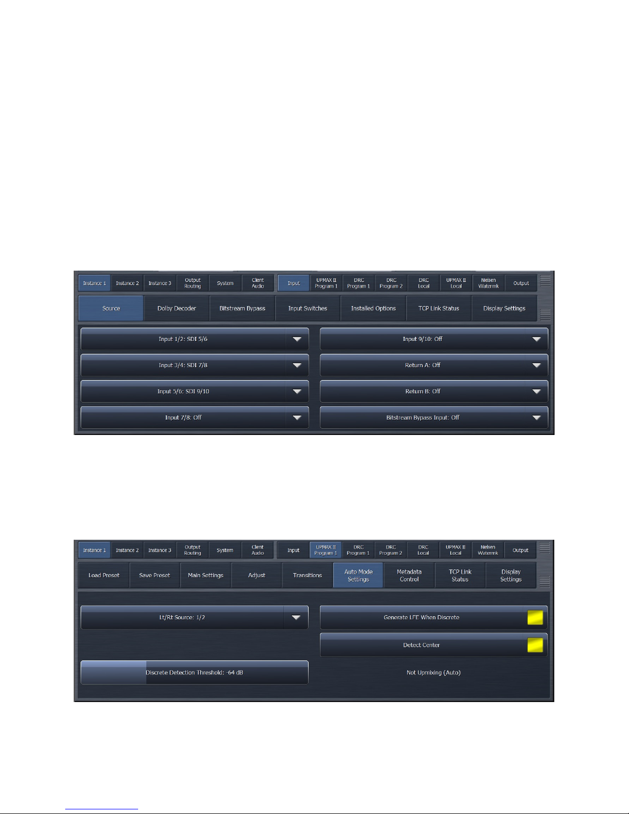
AERO.2000 User Guide July 2016
L16/1/18039
Occasionally stereo content is always present on a given pair. For example, stereo is always on
pair 1/2. When 5.1 surround is present it is on 3 entirely different pairs. For example, Pairs 3, 4
and 5.
AERO.2000 can upmix pair 1 and automatically switch to the 5.1 surround pairs when 5.1
surround audio is present. If a program with stereo only content appears the AERO will switch
back to the stereo source.
To configure this example, select SDI 5/6, 7/8 and 9/10 as the sources for Program 1 Inputs 1/2,
3/4, 5/6. See Figure 9-1.
Instance 1 > Input > Source
Figure 9-1 Instance 1, Source select for DRC Program 1
To set the stereo source select input ½ as the Lt/Rt source on the UpMAX Program 1 Auto
Mode tab. See Figure 9-2.
Instance 1 > UpMAX II Program 1 > Auto Mode Settings
Figure 9-2 Instance 1, UpMAX Program 1, Auto Mode Settings
©2016 LINEAR ACOUSTIC INC. THE TELOS ALLIANCE. ALL RIGHTS RESERVED
Page 77
Page 92

AERO.2000 User Guide July 2016
L16/1/18039
The Lt/Rt Source drop down allows the selection of inputs 1/2, 7/8, or 9/10 as the stereo
source. Any 3 input pairs can be selected as the 5.1 surround source channels for Program 1
Input channels 1/2, 3/4, 5/6. These three AMX5.1 inputs are always used for the 5.1 surround
program source.
©2016 LINEAR ACOUSTIC INC. THE TELOS ALLIANCE. ALL RIGHTS RESERVED
Page 78
Page 93
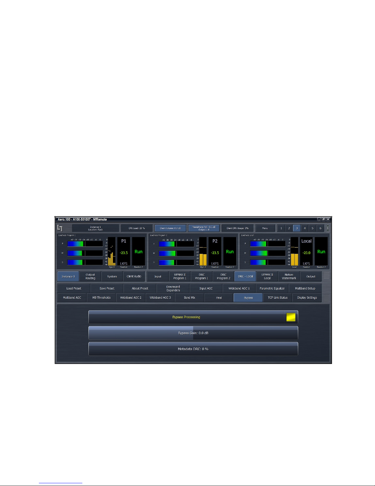
AERO.2000 User Guide July 2016
10
10 Troubleshooting
1010
AERO.2000 is reliable and easy to install. Most problems turn out to be wiring or configuration
errors. However, it is a powerful processor with many possible configurations and useradjustable parameters.
Troubleshooting
TroubleshootingTroubleshooting
• If you cannot find the source of a problem, simplify the signal path.
• Hard bypass is one of AERO.2000’s best troubleshooting features. To instantly remove
AERO.2000 from the signal path, go to:
System > I/O Setup > H/W I/O Setup > Master Bypass and enable the Master Bypass
• Master Bypass enables the relay bypass of SDI in to SDI out and each AES input to its
corresponding output.
• To remove processing from the signal path but retain the signal flow each DRC can be
switched to bypass. See Fig. 6.1, below.
L16/1/18039
• Bypass sets all gain control elements to unity. The entire signal path and the latency
is maintained but no processing is active.
©2016 LINEAR ACOUSTIC INC. THE TELOS ALLIANCE. ALL RIGHTS RESERVED
Fig 10-1 DRC Bypass setting
Page 79
Page 94

AERO.2000 User Guide July 2016
• Viewing the hardware I/O and Instance I/O meters is a good trouble shooting tool
when configuring SDI embedding, DRC Inputs and Output Routing.
10.1
10.1 The unit does not power on
10.110.1
10.2
10.2 Dialogue
10.210.2
The unit does not power on
The unit does not power onThe unit does not power on
1. Check whether the front panel logo is back-illuminated blue and that the fan is turning
when AC power is applied.
2. The boot process may take up to two minutes. If the unit boots, you are done.
3. If the fan spins but the unit still does not boot, continue to 4 below.
4. Remove the AC cords and wait two minutes.
5. Plug both AC cords back in to power the unit on.
6. AERO.2000 will automatically power back on.
Dialogue causes surrounds to pump
DialogueDialogue
causes surrounds to pump
causes surrounds to pumpcauses surrounds to pump
L16/1/18039
The current preset may be too aggressive, fast, or the Gate and Freeze settings are
inappropriate for the content. Since all processing channels in a program are linked, they all
receive the same gain reduction and expansion. The loudest channel initiates the gain control,
so it can seem that the surrounds are ducked by dialogueue. Choose a moderate preset, and
then carefully adjust Gate and Freeze so crowd noise does not increase when dialogueue stops.
10.3
10.3 Output audio clicks and pops
10.310.3
When using the AES-3 inputs the AES reference may be missing or at the wrong sample rate;
the unit expects to lock to 48 kHz. AERO.2000 defaults to an internal 48 kHz reference if the
external reference is removed or missing. This allows audio to continue, but with asynchronous
inputs and outputs (due to the sample rate converters on each input pair). Make sure to
connect a valid reference signal to avoid this issue.
An improper reference signal in equipment located upstream or downstream from AERO.2000
can also cause output noise. Use Master Bypass to verify that AERO.2000 is not the problem.
System > I/O Setup > H/W I/O Setup > Master Bypass and enable the Master Bypass
SDI sources that are not synchronous may cause pops and clicks in the audio when switched to
the AERO.2000. Auto-correction of this state can cause 10 seconds or more of audio muting
while the unit re-syncs. If this is the case put a video frame synchronizer in front of the
AERO.2000 SDI input.
Output audio clicks and pops
Output audio clicks and popsOutput audio clicks and pops
©2016 LINEAR ACOUSTIC INC. THE TELOS ALLIANCE. ALL RIGHTS RESERVED
Page 80
Page 95

AERO.2000 User Guide July 2016
An Ethernet connection to the AERO.2000 that is unstable (i.e. bad port or other network issue)
can cause the same issue as switching unsynchronized sources into the AERO.2000. The
Ethernet connection must be stable.
10.4
10.4 Dolby Digital, Dolby Digital Plus or Dolby E output
10.410.4
When using the internal Dolby Digital (Digital Plus or E) encoder noise in the Dolby encoded
signal is usually caused by not having a proper reference with respect to the DTV video
encoder/multiplexer. All gear should be referenced to the local plant timing. In some cases, i.e.
some Tandberg devices), the multiplexer generates a special reference signal that must be
routed back to the AERO.2000 and used as its reference. Consult your DTV encoder reference
manual for more details.
10.5
10.5 Audio sounds strange
10.510.5
Audio that sounds reverberant, hollow or like sound in a tunnel indicates timing differences
between the audio channels. Stereo viewers are usually the first to notice such problems. The
delay settings in AERO.2000 should all be equal, or set explicitly. Offsets of just a few
milliseconds can be audible under the right conditions.
For those using a Dolby DP564 AC-3 decoder, one of the monitoring modes uses the analog and
digital outputs. This can inject up to 10 ms of delay into the surround channels, which usually
elicits complaints. Either bypass the unit or set the monitoring mode to Digital.
Dolby Digital, Dolby Digital Plus or Dolby E output dropouts
Dolby Digital, Dolby Digital Plus or Dolby E output Dolby Digital, Dolby Digital Plus or Dolby E output
Audio sounds strange
Audio sounds strangeAudio sounds strange
L16/1/18039
dropouts
dropoutsdropouts
10.6
10.6 Audio issues disappear in
10.610.6
Since AERO.2000 can apply significant gain to incoming signals, previously inaudible sounds may
get pulled out of the background. We recommend listening carefully to the station audio for
hums, buzzes, clicks, pops, phase issues, frequency response problems, bass build-up and other
problems in the source audio. When amplified, these artifacts can ruin otherwise excellent
programming.
Ensure that the input audio is immaculately clean or it will sound worse in surround!
Ensure that input channels 3, 4, 5 and 6 are silent when source programs changes between
stereo and surround. Alternately, use a GPI or command over IP to Mute 3/4 and 5/6.
10.7
10.7 Audio fixed by re
10.710.7
Re-booting sometimes fixes audio problems simply because the AERO.2000 re-locks to the
digital input when it restarts. The AERO restart also causes all downstream devices to re-lock to
the incoming signal after reboot. This may hide a timing problem with the incoming signal.
©2016 LINEAR ACOUSTIC INC. THE TELOS ALLIANCE. ALL RIGHTS RESERVED
Audio issues disappear in bypass
Audio issues disappear in Audio issues disappear in
Audio fixed by re----boot
Audio fixed by reAudio fixed by re
boot
bootboot
bypass
bypassbypass
Page 81
Page 96

AERO.2000 User Guide July 2016
Instead of rebooting, remove the input(s) to the AERO, wait 10 seconds and reconnect. If this
fixes the problem (temporarily) it is likely that there is a timing problem with the incoming
signal or the AERO reference setting.
Selecting a preset with minimal processing (i.e., Protection Limit) may shed further light on the
problem by allowing the input audio to be heard with no loudness control.
10.8
10.8 Audio has artifacts
10.810.8
Sometimes described as “squirrels in the surrounds,” this is almost always caused by source
material that has been low bit-rate encoded and then transcoded back to LPCM. Program
delivery services or server systems use MPEG 1, Layer 2 audio data reduction to save
bandwidth. At 256 kbps or higher per stereo pair, there are no issues. However, at or below
128 kbps coding artifacts in the original stereo signal can be unmasked by upmixing and by
loudness control. This inferior content has similar results without upmixing if viewers matrixdecode the signal. Matrix decoding is the default mode for most home A/V receivers. We
recommend contacting the program provider or server manufacturer. Bandwidth is so
inexpensive that there is no good reason to run audio coding at bit rates lower than 256 kbps
stereo.
Audio has artifacts
Audio has artifactsAudio has artifacts
L16/1/18039
©2016 LINEAR ACOUSTIC INC. THE TELOS ALLIANCE. ALL RIGHTS RESERVED
Page 82
Page 97
AERO.2000 User Guide July 2016
11
11 Specifications
1111
Specifications
SpecificationsSpecifications
L16/1/18039
Processing
Structure
Algorithms
Options
Table 11-1 Electrical
AMX 5.1 Instance: 5.1+2+2 with up to 2 downmix
outputs, dual-path upmixing and SAP/DVS capability.
AMX2.0 Instance: 2+2+2 with Auto SAP/DVS with 3 downmix outputs and SAP/DVS
capability.
AMX5x2 Intance: 2+2+2+2+2 with 2 downmix outputs and SAP/DVS capability.
AEROMAX®: ITU-R BS.1770-3 and EBU R128-compliant loudness control via
adjustable wideband and multiband processing.
UPMAX®II: 5.1-channel upmixing, automatic bypass of discrete content
Dolby Digital and Dolby Digital Plus encoding; 3/2L or 2/0 for AMX5.1 instance.
AMX2.0 instance is limited to 2/0 encoding.
Dolby E Encoding
Dolby Digital, Dolby Digital Plus, and Dolby E decoding; auto sensing of coded or
PCM audio.
Nielsen Watermark Encoder
Low latency mode
Crowd Control
ITU or EBU labeled metering
Headphone Output
Frequency Response
Level
Connector
Digital I/O
©2016 LINEAR ACOUSTIC INC. THE TELOS ALLIANCE. ALL RIGHTS RESERVED
AES Digital Audio I/O
Remote
20 Hz–20 kHz, 1 dB (Protection Limit preset)
+12 dBu maximum
1/4-in (6.35-mm) front panel jack with volume control
All inputs are unbalanced, 75 ohm, with internal
termination 1-2, 3-4, 5-6, 7-8, AES Ref use BNC (F)
connectors.
4 AES pairs of auxiliary digital I/O on F-DB25 connector
Signal levels per SMPTE 276M/ AES-3ID-2001
All I/O can be assigned as needed
TCP/IP remote control and audio monitoring via Remote Interface software, a
Windows®-compatible application (included)
HTTP server allows get/set control from any OS
Page 83
Page 98

AERO.2000 User Guide July 2016
L16/1/18039
Ethernet
GPI/O Control Port
Metadata Input
Reference
HD/SD-SDI
Auto-Sensing I/O
Analog Audio I/O
100 to 1000 BASE-T via RJ-45 connector
F-DB25 connector, 0–5 V TTL levels, pull to ground activation. 8 GPIs.
DB9-F connector, 115 kbps, pinout per SMPTE 207M (RS-422/485)
Interfaces directly with Dolby Metadata (SMPTE RDD6)
48 kHz via AES DARS reference input or SDI input
De-embed up to 16 audio channels from SDI, process and/or encode, and reembed up to 16 channels
Signal levels per SMPTE 292M /259M
Supports SMPTE 2020 A and B VANC metadata
Supports up to 1080p/60/59.94/50 Hz
Balanced left and right inputs. Max input dB ref .775 V
Balanced left and right outputs. Max output level dB ref .775 V
DB9-F connector
Table 11-2 Physical
2RU
Dimensions
Net Weight
Environmental
Power Requirements
11.1
11.1 Latency
11.111.1
Latency
LatencyLatency
H = 3.50 in (90 mm) W = 19 in (483 mm) D = 13.25 in (337
mm)
12.5 lb (6 kg) approximate
Operating: 0 – 50ºC
Non-operating: -20 – 70ºC Fan
cooled
Dual redundant auto-sensing power supplies, each rated at
100–240 VAC, 50–60 Hz, 175 W maximum
The latency of PCM audio is fixed at 180 ms.
Latency of Dolby Digital Plus encoder is fixed at 64 ms.
Nielsen watermark encoding does not cause additional latency.
Disabling sample rate conversion (SRC) for any AES input decreases the latency on that pair by
1.5 ms. If a Dolby encoded bitstream is connected to an AES input the SRC must be disabled.
©2016 LINEAR ACOUSTIC INC. THE TELOS ALLIANCE. ALL RIGHTS RESERVED
Page 84
Page 99

AERO.2000 User Guide July 2016
L16/1/18039
Synchronization between audio and video is achieved via the included Compensating Video
Delay and instance audio delays.
A Low Latency mode is available by request.
• Low latency mode does not allow for any Dolby or Nielsen encoding options in the
AERO.2000
• Processing latency with UpMAX upmixing OFF (disabled) is 45 ms.
• Enabling UpMAX upmixing adds 16ms (stereo content or passthrough of 5.1 surround
content)
• Disabling sample rate conversion (SRC) for any AES input decreases the latency on that pair
by 1.5 ms. If a Dolby encoded bitstream is connected to an AES input the SRC must be
disabled.
11.2
11.2 Connector Pinouts
11.211.2
Connector Pinouts
Connector PinoutsConnector Pinouts
Pin Function
1 Left In +
2 Right In +
3 Left Out +
4 Right Out +
5 GND / Shield
6 Left In -
7 Right In -
8 Left Out -
9 Right Out -
Table 11-3 Analog I/O (F-DB9)
©2016 LINEAR ACOUSTIC INC. THE TELOS ALLIANCE. ALL RIGHTS RESERVED
Page 85
Page 100

AERO.2000 User Guide July 2016
NC
L16/1/18039
Table 11-4 Metadata Input Port Pinout
Pin Connection
1
2
3
4
5
6
7
8
9
Shield
TX A asynchronous data out –
RX B asynchronous data in +
Ground
Ground
TX B asynchronous data out +
RX A asynchronous data in –
Shield
F-DB9 connector with full-duplex RS-485 protocol running at 115 kbps. Pinout is compatible
with SMPTE 207M. Pin-for-pin compatible with Dolby Metadata (SMPTE RDD6).
©2016 LINEAR ACOUSTIC INC. THE TELOS ALLIANCE. ALL RIGHTS RESERVED
Page 86
 Loading...