

Page 1
QUICK START GUIDE FOR DEMO CIRCUITS 530A-A AND 530A-B
LI-ION BATTERY CHARGER
LTC4050
DESCRIPTION
Demonstration circuit 530A-A and 530A-B are complete
constant-current/constant-voltage battery chargers designed to charge one Lithium-Ion cell. Both feature the
LTC4050 Linear Battery Charger driving a P-channel
MOSFET in a series pass linear regulator configuration
for charging at a maximum current of 700mA (limited by
the power dissipation capabilities of the pass transistor).
Demo board LTC4050A-A features the LTC4050-4.1,
which has a recharge threshold voltage of 3.88V, making
it suitable for charging 4.1V cells.
Demo board LTC4050A-B features the LTC4050-4.2,
which is recommended only for charging a 4.2V cell,
due to its recharge threshold voltage of 3.98V.
Other Features include:
•
Preset float voltages of 4.1 and 4.2V ±1%
•
700mA Constant Current (can be programmed for
other charge currents)
•
3-hour charge termination timer. This timer can be set
for other time periods through a capacitor change.
For instance, you may want to use a much shorter period (on the order of 30 seconds) when evaluating the
board with a battery simulator instead of a Li-Ion battery.
•
Manual Shutdown
•
C/10 Trickle charge for deeply discharged batteries
•
Auto recharge when battery voltage drops below preset threshold (3.88V for DC530A-A and 3.98V for
DC530A-B).
•
Low battery drain current when the input supply is
removed
•
Input Power OK LED indicator (ACPR)
•
C/10 Charge LED indicator (CHRG)
•
NTC Input to prevent charging if the battery is too hot
or too cold
Small surface mount components are used to minimize
board space and height with the circuitry occupying approximately 0.15 square inches of board space with a
height of 0.054 inches (1.4mm).
Design files for this circuit board are available. Call
the LTC factory.
Table 1. Performance Summary
PARAMETER VALUE
Input Voltage Range 4.5V to 6.0V (upper range limited by MOSFET dissipation)
Output Voltage V
Output Current I
Output Current I
C/10 CHRG LED Threshold Level 35-140mA
Trickle Charge Threshold Voltage 2.49V
Battery Drain Current with VIN Removed 5µA
(constant voltage mode) 4.1V ±1% DC530A-A
BAT
(constant current mode) 700mA ±8%
BAT
(trickle current mode) 70mA ±70%
BAT
4.2V ±1% DC530A-B
Note: If V
age current of the input Schottky diode. A silicon diode could be used for the input diode if the
slightly greater forward voltage drop is not a problem.
is pulled down to 0V, the current drain from the battery will be higher due to the leak-
IN
1
Page 2

QUICK START GUIDE FOR DEMO CIRCUITS 530A-A AND 530A-B
LI-ION BATTERY CHARGER
QUICK START PROCEDURE
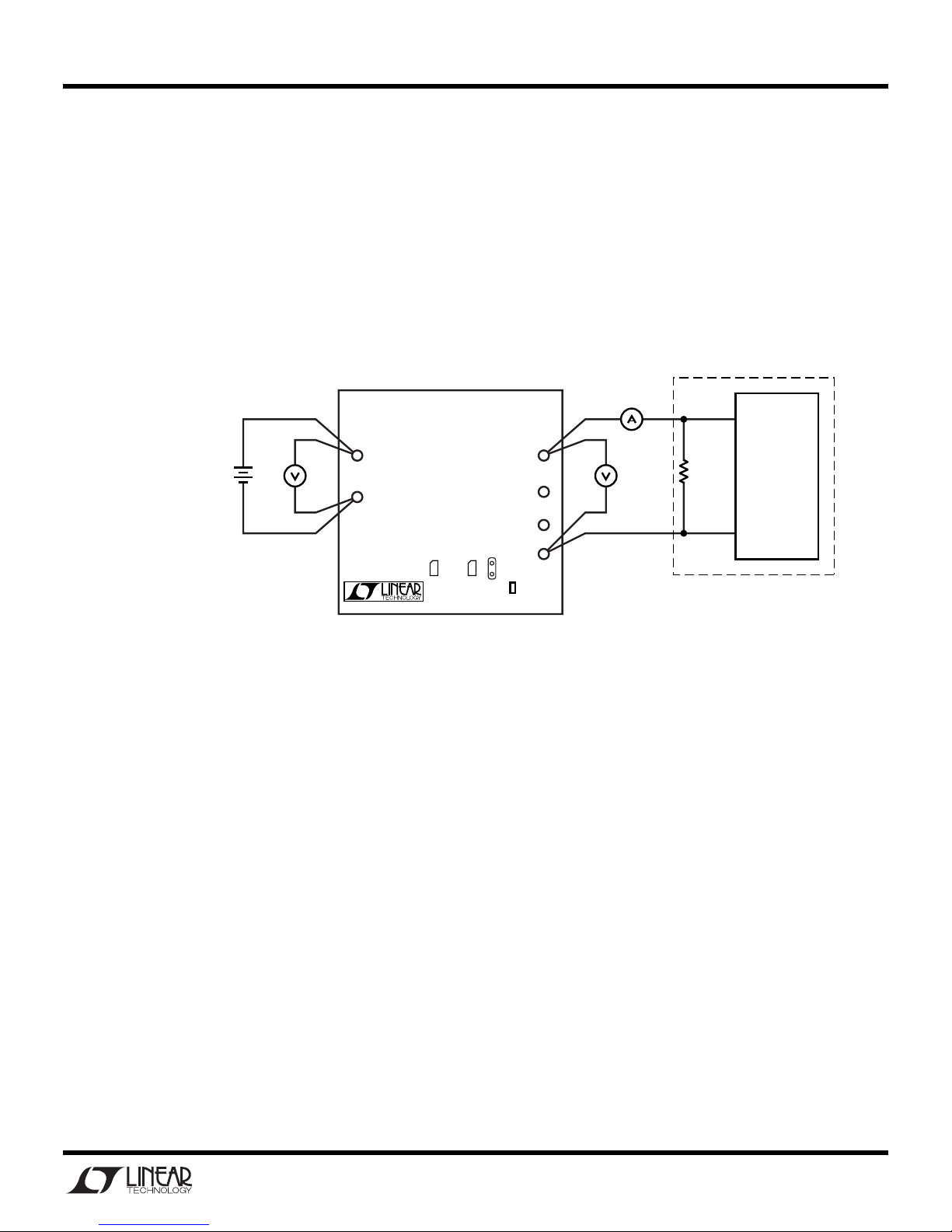
Demonstration circuits 530A-A and 530A-B are easy to
set up to evaluate the performance of the LTC4050. Refer to Figure 1 for proper measurement equipment setup
and follow the procedure below:
1.
Install jumper JP1 in the PROG position to enable the
charger.
2.
Set the input power supply to 0V, and then connect it
to the VIN and GND pins of the demo board.
3.
Set the battery simulator to 0V, and then connect it to
the BAT and GND pins.
4.
Connect the digital voltmeters as shown in the setup
diagram to measure VIN, charger voltage (VBAT) and
the charge current (IBAT).
5.
Start the demo board evaluation by increasing the
input power supply to approximately 3.8V (battery
simulator power supply set for 0V). The charger output voltage and charge current should be 0. The
CHRG and ACPR LEDs should be off.
off due to the undervoltage lockout feature.
6.
Increase the input voltage to 5V and keep the battery
The charger is
simulator power supply at 0V. Both LEDs (CHRG and
ACPR) should now be on, the charger output voltage
(VBAT) should be approximately 140mV, and the
charge current should be approximately 70mA.
This
is the trickle charge mode for a deeply discharged
battery.
Typically, a battery that has not been charged
for a long time.
7.
Starting from 0V, slowly increase the battery simulator power supply (VBAT), observing the charger’s
output voltage on the DVM. When the charger’s output voltage exceeds approximately 2.5V, the charger
will suddenly enter the Constant current portion of the
charge cycle resulting in an abrupt increase in charge
current (IBAT) to the programmed value of approximately 700mA.
This is the constant current mode.
voltage is within approximately 10mV of the preset
charge voltage, at which time the charge current will
begin to decrease.
stant voltage portion of the charge cycle.
9.
Continue slowly increasing the battery simulator
This is the beginning of the con-
power supply until the charge current drops to approximately 200mA, and then read the charger output
voltage.
This reading is the charger float voltage
(VBAT) which will be either 4.1V or 4.2V ± 40mV
depending on the demo board version.
10.
Place jumper JP1 in the SHDN position. The charger
will shut down, dropping the charge current to 0mA.
The ACPR LED remains on and the charge LED goes
out.
11.
Return JP1 to the PROG position.
12.
Continue slowly increasing the battery simulator
power supply while observing the CHRG LED. The
LED will go out when the charge current drops to approximately 10% of the programmed charge current
of 700mA.
ating correctly.
This verifies that the C/10 output is oper-
The current through the LED drops from approximately 10mA when the LED is on, to approximately
30µA when the charge current drops to 10%, and
drops to 0µA after the timer has timed out (3 hours
when a 0.1µF timing capacitor is used).
At C/10, when the CHRG LED goes out, the battery is
approximately 94% charged. The charger will continue charging for a total of 3 hours (0.1µF timing capacitor) and then stop, at which point the battery is
approximately 99% charged.
NOTE:
For evaluation purposes, the time can be decreased from the programmed 3 hours to approximately 30 seconds by reducing the timer capacitor
(C3) from 0.1µF to 270pF.
8.
Continue slowly increasing the battery simulator
power supply, thus simulating a battery accepting
charge. The charge current should remain at the programmed value of 700mA until the charger output
13.
After the timer has timed out, slowly decrease the
battery simulator power supply. At approximately
3.88V for demo board DC530A-A, a new 700mA
charge cycle begins. With demo board DC530A-B,
2
Page 3
QUICK START GUIDE FOR DEMO CIRCUITS 530A-A AND 530A-B
LI-ION BATTERY CHARGER
this should occur at approximately 3.98V.
Recharge Threshold Voltage.
14.
To verify battery drain current, remove the input sup-
This is the
ply voltage, and set the battery simulator power supply to approximately 4V.
now read battery drain current.
If V
is pulled down to 0V, the current drain from the
IN
The charge current DVM will
battery will be higher due to the leakage current of the
input Schottky diode. A silicon diode could be used
LTC4050EMS
Li-Ion Battery Charger
Demo Circuit DC530A-A or B
INPUT POWER SUPPLY
DO NOT EXCEED 6V
MOSFET WILL OVERHEAT
0–6V
+
+
1A
–
VIN
–
GND
D2
Linear Technology (408) 432-1900 www.linear.com
Figure 1. Proper Measurement Equipment Setup
CHRG
for the input diode if the slightly greater forward voltage drop is not a problem.
15.
Operation of the NTC function is verified as follows.
Placing a 5k resistor from the NTC pin to GND can
simulate too hot operation. In order to verify too cold
operation R7 has to be removed and replaced by a
33k resistor. While charging is inhibited by an out of
spec NTC both the CHRG and ACPR LEDs will be ON.
ACPR
MEASURE
CHARGE
CURRENT
)
(I
BAT
+–
+
BAT
SHDN
NTC
SHDN
GND
R7
JP2D3
VBAT
–
* CAN USE A LI-ION BATTERY,
THOUGH TESTING TAKES MORE TIME
RECOMMENDED
LI-ION BATTERY SIMULATOR*
BATTERY
+
SIMULATOR
BENCH
2Ω
10W
PRELOAD
POWER SUPPLY
0V–4.3V
WITH COURSE
AND FINE
VOLTAGE
–
ADJUSTMENT
2A
NOTE:
Although it would take more time, this charger can also be evaluated using a rechargeable Li-Ion battery in
place of the battery simulator pictured here. If you use a real battery, keep the DC resistance between the charger and
the battery to a minimum, as this will affect the charge current in the constant voltage mode.
3
Page 4
QUICK START GUIDE FOR DEMO CIRCUITS 530A-A AND 530A-B
LI-ION BATTERY CHARGER
Constant Current Mode Constant Voltage Mode
700mA
600mA
500mA
400mA
300mA
CHARGE CURRENT (mA)
200mA
100mA
0
0 2 0 4 0 6 0 8 0 100 120 140 160 180
Charge Current
60˚
50˚
40˚
30˚
Timer Capacitor = 0.1µF
Ta = 25˚C
0.5 Hr 1 Hr 1.5 Hr 2 Hr 2.5 Hr 3 Hr
TIME (minutes or hours)
Battery Voltage
C/10
LED
OFF
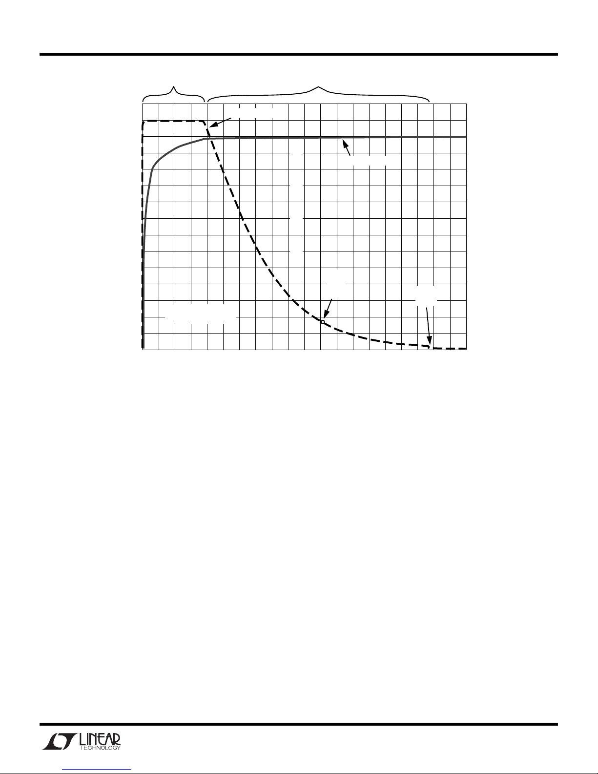
Figure 2. Typical Charge Cycle Using DC530A-A
Timer
Stops
Minutes
Hours
4.2V
4.0V
3.8V
3.6V
3.4V
3.2V
3.0V
2.8V
CHARGE VOLTAGE (V)
4
Page 5
5
5
4
4
3
3
2
2
1
1
D D
C C
B B
A A
Li-lon Cell
BAT
Single
+VIN
EXT. NTC
GND
4.5V - 6V
GND
EXT. PROG / SHDN
PROG
SHDN
VERSION
VERSION TABLE
U1
Battery Voltages
*
*
DC530A-A
DC530A-B
4.1V
4.2V
LTC4050EMS-4.1
LTC4050EMS-4.2
CHRG
ACPR
A
DC530A
Tuesday, July 09, 2002
1
1
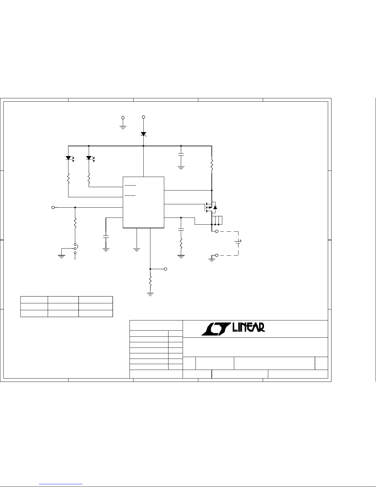
LTC4050EMS, Li-Ion Battery Charger with NTC
June Wu 4/30/02
Fran Hoffart 4/30/02
SIZE
SCALE:
CAGE CODE
DWG NO
REV
SHEET
OF
FILENAME:
TITLE
CONTRACT NO.
APPROVALS
DATE
DRAWN
CHECKED
APPROVED
ENGINEER
DESIGNER
TECHNOLOGY
1630 McCarthy Blvd.
Milpitas, CA 95035
Phone: (408)432-1900
Fax: (408)434-0507
VCC
D1
MBRM120LT3
1 2
R2
18.7K
D2
RED
2 1
D3
GRN
2 1
C1
1uF
16V
R4
330
E1
Q1
SI3443DV
3
41
256
U1
LTC4050EMS
8
3
10
4
5
6
7
9
1
2
VCC
CHRG
ACPR
TIMER
GND
PROG
DRV
SENSE
BAT
NTC
E3
R3
330
C3
0.1uF
16V
E5
JP1
1
2
3
R1
0.15
1/4W
R7
10K
E4
R6
1 ohm
E6
E2
C2
4.7uF
6.3V
 Loading...