

Linear LTC4002-4.2 Quick Start Manual

QUICK START GUIDE FOR DEMONSTRATION CIRCUIT 551
DESCRIPTION
LITHIUM-ION BATTERY CHARGER WITH CHARGE TERMINATION
LTC4002-4.2
Demonstration circuit 551 is a complete constantcurrent/constant- voltage battery charger designed
to charge one Lithium-Ion cell. Programmed for 3A
charge current, this board features a 500kHz step
down switching regulator controller driving a Pchannel MOSFET. A fixed 3 hour timer is included
for charge termination in addition to a charge status
LED to indicate a near-full-charge condition and a
thermistor connection for battery temperature
charge qualification. Because of the heat generated
by the circuit, the thermistor must not be mounted
Other Features include:
• Preset float voltages of 4.2V ±1%
• 3A Constant Current (can be programmed for other charge currents)
• 3 Hour charge termination timer
• NTC Thermistor input for sensing battery temperature
on this board. A 10k resistor (R3) is used instead of
a thermistor on this board.
The LTC®4002 on this board is in a tiny 3 X 3 mm
10 pin DFN package. All surface mount components
are used to minimize board space and height with
the circuitry occupying approximately 0.5 square
inches of board space although additional pc-board
copper is needed for heat dissipation.
Design files for this circuit board are available.
Call the LTC factory.
LTC is a registered trademark of Linear Technology Corporation
• Undervoltage Lockout
• Manual Shutdown
• Low battery drain current when input supply is removed
• C/10 Trickle charge for deeply discharged batteries
• Auto recharge when battery voltage drops below preset threshold
• C/5 Charge LED indicator (CHRG)
1
QUICK START GUIDE FOR DEMONSTRATION CIRCUIT 551
Measure Charge Current
Li-Ion Battery Simulato
r
(I
)
LITHIUM-ION BATTERY CHARGER WITH CHARGE TERMINATION
Typical Demo Board Specifications
Input Voltage Range (VIN) 5.2V to 24V
Charge Voltage (V
Charge Current I
Charge Current I
C/5 CHRG LED Threshold Level 750mA ± 25%
Trickle Charge Threshold Voltage 2.9V
) (constant voltage mode) 4.2V ±1%
BAT
(constant current mode) 3A ±8%
BAT
(trickle current mode) 350mA ± 20%
BAT
Battery Drain Current with VIN Removed <20µA *
* Main cause of drain current is due to Schottky diode leakage current.
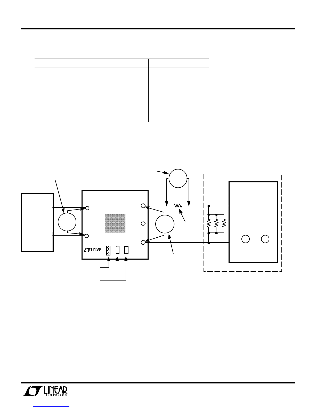
Figure 1. Test Setup
Measure Input Voltage
Input
Power
Supply
0 to 25V
@3A
+
Volt
Meter
-
SHDN/RUN Jumper
CHARGE LED
NTC Thermister (10k Resistor)
+V
IN
GND
TECHNOLOGY
(408)432-1900
LTC4002EDD
Demo DC55 1 A
100mV/Amp
BAT
EXT
NTC
GND
BAT
Measure Charger
Output Voltage (V
Volt
Meter
0.1 Ohm
1%
Volt
Meter
Current
Sense
Resistor
BAT
Preload
Resistors
2 Ohm
10W
)
3 ea.
Battery
Simulator
Bench Power
Supply
+
0V to 5V
@6A
-
Course Fine
Voltage Adjust
Test Equipment Required for Demo Board Evaluation
Lab power supply for input power 0 to 25V @ 3A
Digital multimeter for measuring input voltage (VIN) 3-1/2 digits
Digital multimeter for measuring battery voltage(V
Digital multimeter for measuring charge current 3-1/2 digits
Li-Ion cell or
*Battery Simulator
) 4-1/2 digits
BAT
4.2V Rechargeable Li-Ion Cell
2

QUICK START GUIDE FOR DEMONSTRATION CIRCUIT 551
LITHIUM-ION BATTERY CHARGER WITH CHARGE TERMINATION
*Battery Simulator consists of;
Power supply with coarse and fine output voltage adjust controls 0 to 5V @ 6A
Power resistors (preload for power supply) 3ea 2• 10W
Battery Simulator
A battery simulator can be very useful for
evaluating a battery charger. A simple battery
simulator consists of a lab power supply with
coarse and fine (or a multi-turn) voltage adjust
controls and a power resistor connected to the
power supply output terminals. With the resistor
load connected, the power supply can source and
sink current, similar to an actual battery. Any level
of charge from a fully discharged to fully charged
battery can be quickly simulated by simply
changing the battery simulator power supply
voltage. A fully discharged Li-Ion cell will be
approx. 2.6V to 3V and a fully charged cell will be
either 4.1V or 4.2V depending on the battery
chemistry. When the cell is nearly fully charged,
small changes in battery voltage will result in large
changes in charge current.
Of course, there are times when an actual battery is
needed, for example when plotting a complete
charge cycle from start to finish.
QUICK START PROCEDURE
With both power supplies set to 0V, connect the
demo board to power supplies and meters as
shown in Figure 1. The electrical connections
between the charger output and the battery
simulator must be high quality and a 0.1Ω sense
resistor is recommended for the charge current
measurement. The dc resistance in the charge
current path should be kept to a minimum.
Undervoltage Lockout and Trickle Charge - After
placing jumper (JP1) in the “RUN” position, begin
increasing the input power supply voltage. At
approximately 4.3V, the LTC4002 undervoltage
lockout will allow the charger to start and the
charge current will abruptly rise to approximately
300mA (30mV on the meter). This is the trickle
charge current for a deeply discharged battery (V
< 2.9V). Adjust the input supply to approximately
6V.
Trickle Charge Threshold and Constant Current
Charge - Begin increasing the battery simulator
power supply (V
voltage on the DVM. When the voltage exceeds
), observing the charger output
BAT
BAT
approximately 2.9V, the charger will suddenly enter
the Constant Current portion of the charge cycle
resulting in an abrupt increase in charge current to
the programmed value of approximately 3A (300mV
on the charge current DVM). This is the constant
current mode. The CHRG LED will also turn on.
Constant Voltage Charge and CHRG LED Indicator -
Continue slowly increasing the battery simulator
power supply, thus simulating a battery accepting
charge. The charge current should remain at the
programmed value of 3A until the charger output
voltage is within approximately 10mV of the preset
charge voltage (4.2V ±1%), at which time the charge
current will begin to decrease. This is the beginning
of the Constant Voltage portion of the charge cycle.
Continue very slowly increasing the battery
simulator power supply until the CHRG LED turns
off, and note the charge current level when it went
off. The current level should be approximately
750mA ±25%. The LED is an indicator that the
battery is approaching full charge. It is not a charge
complete indication. The charge cycle will continue
until the 3 hour timer ends. (Note: when the LED
3
 Loading...