

Page 1

QUICK START GUIDE FOR DEMONSTRATION CIRCUIT 802
DESCRIPTION
LTC3828 DUAL 2-PHASE STEP DOWN CONVERTER WITH TRACKING
LTC3828EUH
Demonstration circuit 802 features the dual-output,
2-phase synchronous buck regulator LTC3828EUH.
The input voltage range of the demo board is 7V to
21V. The outputs are 5V/5A
and 3.3V/5A
MAX
MAX
. Depending on the setting of the optional resistors and
jumpers, each output can track an external ramp
voltage during start up or one output can track another output on the same board during start up. At
light load, the supplies can operate in high efficiency
mode or low output ripple mode depending on
jumper selection.
The switching frequency is a jumper-selectable
250kHz or 550kHz, or one resistor can set the frequency anywhere in between. The supply can also be
synchronized by an external clock signal. A
CLOCKOUT pin provides an output clock signal to
synchronize other supplies if needed. The
LTC3828EUH regulator IC is in a small 5 mm x 5 mm
package with exposed thermal pad for low thermal
impedance.
Design files for this circuit board are available.
Call the LTC factory.
, LTC and LT are registered trademarks of Linear Technology Corporation.
Table 1. Performance Summary (TA = 25°C)
PARAMETER CONDITION VALUE
Input Voltage 7V-21V
Output Voltage V
Output Voltage V
Maximum Output Current VIN = 7V-21V 5A Each Output
Switching frequency FCB = CCM
Full Load Efficiency VIN = 12V, V
VIN = 12V, V
I
OUT1
I
OUT2
= 0A to 5A 5V ± 2%
OUT1
= 0A to 5A 3.3V ± 2%
OUT2
OUT1
OUT2
= 5V, I
= 3.3V, I
= 5A, fsw=550kHz 93% Typical
OUT1
= 5A, fsw=550kHz 91% Typical
OUT2
Jumper selectable
250kHz or 550kHz
QUICK START PROCEDURE
Demonstration circuit 802 is easy to set up to evaluate the performance of the LTC3828EUH. Refer to
Figure 1 for proper measurement equipment setup
and follow the procedure below:
NOTE:
When measuring the input or output voltage
ripple, care must be taken to avoid a long ground lead
on the oscilloscope probe. Measure the input or output voltage ripple by touching the probe tip directly
1
Page 2
QUICK START GUIDE FOR DEMONSTRATION CIRCUIT 802
LTC3828 DUAL 2-PHASE STEP DOWN CONVERTER WITH TRACKING
across the Vin or Vout and GND terminals. See Figure 2 for proper scope probe technique.
1.
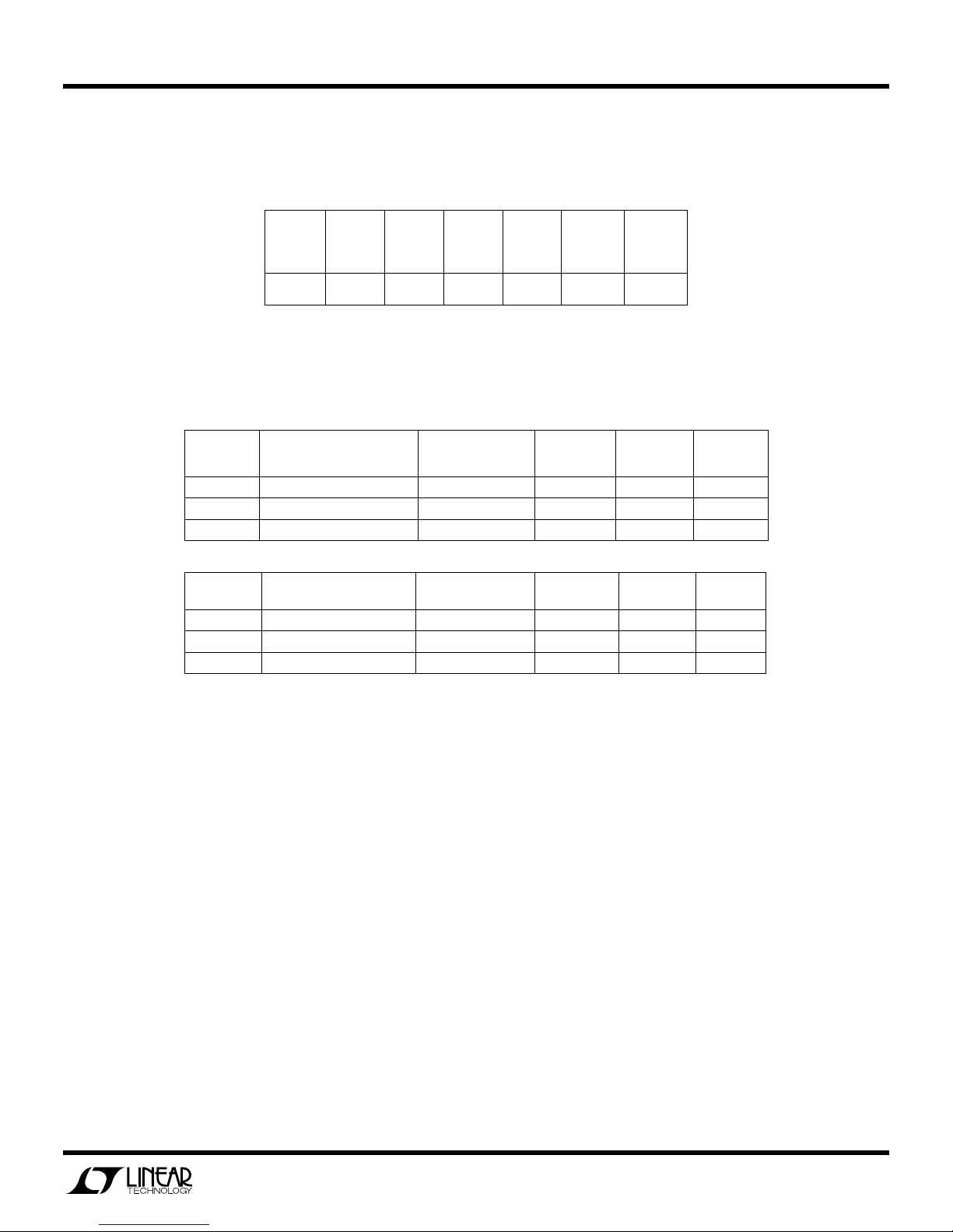
Following table should be the default jumper settings of the DC802A demo board:
JP1
PHSMD
0 550kHz CCM ON ON VOUT1 EXT1
JP2
FSET
JP3
FCB
JP4
RUN1
JP5
RUN2
JP6
TRACK2
JP7
TRACK1
With the above default setting, the supply runs at 550kHz forced continuous current mode.
Following tables show the assembly options for the tracking circuits for VOUT1 and VOUT2:
VOUT1 TRACKING
*
1
2 Track EXT1 EXT1 105K 20K DNP
3 Track VOUT2 VOUT2 105K 20K DNP
OPTIONS TRACK2 JP6 R23 R25 C21
Softstart W/O tracking N/A DNP DNP 0.01uF
VOUT2 TRACKING
1 Softstart W/O tracking N/A DNP DNP 0.01uF
2 Track EXT2 EXT2 95.3K 30.1K DNP
*
3
OPTIONS TRACK1 JP7 R24 R26 C22
Track VOUT1 VOUT1 95.3K 30.1K DNP
*With existing tracking circuit assembly, VOUT1 starts independently (option1). VOUT2 tracks VOUT1 during start
up (option3). Figure 3 shows a typical start-up waveform with tracking.
2.
With power off, connect the input power supply to
VIN and GND. Connect the load between VOUT1
and GND, VOUT2 and GND. Preset the load current
at 0A (minimum). Refer to Figure 1 for correct test
set up.
3.
Turn on the input power.
NOTE:
Make sure that the input voltage does not ex-
ceed 21V.
4.
Check for the proper output voltages. Vout1 =
4.90V-5.10V. Vout2 = 3.23V- 3.36V
NOTE:
If there is no output, temporarily disconnect
the load to make sure that the load is not set too
high.
5.
Once the proper output voltages are established,
adjust the loads within the operating range and observe the output voltage regulation, ripple voltage,
efficiency and other parameters.
2
Page 3

QUICK START GUIDE FOR DEMONSTRATION CIRCUIT 802
VIN
GND
LTC3828 DUAL 2-PHASE STEP DOWN CONVERTER WITH TRACKING
Figure 1. Proper Measurement Equipment Setup
Figure 2. Measuring Input or Output Ripple
3
Page 4

QUICK START GUIDE FOR DEMONSTRATION CIRCUIT 802
LTC3828 DUAL 2-PHASE STEP DOWN CONVERTER WITH TRACKING
Vo1
Vo2
Figure 3. Typical Output Voltage Tracking Waveform during Start-Up
4
Page 5

QUICK START GUIDE FOR DEMONSTRATION CIRCUIT 802
LTC3828 DUAL 2-PHASE STEP DOWN CONVERTER WITH TRACKING
5
 Loading...