

Page 1
Description
DEMO MANUAL DC2313A
Programmable
Six Channel Sequencer and
Voltage Supervisor with EEPROM
Demonstration circuit 2313A showcases the LTC2937, a
programmable six channel power supply sequencer and
voltage supervisor.
The LTC2937 provides flexible sequence control for up
to six power supplies. It enables and disables the sup
plies with
monitors
configurable sequence order and time delays,
the supplies for power-up and power-down time,
-
and for overvoltage and undervoltage. It cooperates with
other LTC2937 parts in the system to coordinate power
sequencing activities. It provides flexible fault response to
autonomously supervise the power supplies, and powerful
debug tools to diagnose any problem that causes a powersupply fault. It holds configuration in non-volatile EEPROM
for completely automatic power system supervision.
The DC2313A board demonstrates the powerful features
of the LTC2937 using six onboard LDO voltage regula
tors, or
by controlling an optional, externally-powered
-
performance summary
DC1361 board (an 8-channel power supply board). Multiple
DC2313A boards can also share timing and sequencing
signals to supervise more than six regulated supplies in
a coordinated manner.
The DC2313A connects to a PC through the DC1613 USB-
2
C/SMBus/PMBus Controller. This connection enables
to-I
the LTpowerPlay™ software, to have complete control over
the LTC2937 through the convenient LTpowerPlay GUI.
The GUI allows control over all of the LTC2937 registers,
and visibility into the status of the part in real time, and
it works with Linear Technology demo boards as well as
2
custom boards with an I
C interface.
Design files for this circuit board are available at
http://www.
L, LT, LTC, LTM, Linear Technology and the Linear logo are registered trademarks and
LTpowerPlay is a trademark of Linear Technology Corporation. All other trademarks are the
property of their respective owners.
linear.com/demo/DC2313A
PARAMETER CONDITIONS MIN TYP MAX UNITS
Voltage Range All 6 12 14 V
V
IN
Current to the Board Sequenced-Down 3.8 mA
I
IN
Current Sequenced-Up, No Loads 17.5 mA
I
IN
V1-V6 Voltage Range Volts at the Turret 0 6 V
EN1-EN6 Voltage Range Volts at the Turret
Regulated LDO Voltage Tolerance Load Current < 20mA –1 1 %
Rated Output Current *V_OUT pins Load Current Per Channel 20 mA
Board Operating Temperature Powered 0 60 °C
Serial Clock Frequency I
†
NOTE: Analog switches U7, U8, and U9 (LTC222) are powered by 5V, and limit the maximum voltage range allowed at their S and D pins. The LTC2937
can tolerate up to 16.5V on its ENn pins.
†
2
C Bus Operating 10 400 kHz
0 6 V
dc2313af
1
Page 2
DEMO MANUAL DC2313A
Ltc2937 features
• Time and Event-Based Supply Sequencing
• 12Programmable Undervoltage and Overvoltage Com-
parators (0.75% Accuracy)
• Stalled
• Single
sion to 50 Devices (300 Power Supplies)
• Configuration and Fault Logging in EEPROM
• EEPROM Rated to 85°C, 10k Writes, 20 Year Retention
Power-Supply Detection
Wire Synchronization Allows Controller Expan
-
how to use this Document
This demonstration manual introduces the LTC2937
through a series of simple exercises using the DC2313A
demo board and the LTpowerPlay software. Each exercise
introduces one or two key features of the part, as well as
• Supported by LTpowerPlay GUI
• Fault and System Status Registers
• Reset Output with Programmable Delay
2
C/SMBus Interface
• I
• Wide Input Supply Voltage Range: 2.9V to 16.5V
• 28-Pin QFN (5mm × 6mm) Package
recommended methods for interfacing to it. The LTC2937
has more useful features than can be covered here. The
user is referred to the LTC2937 data sheet, and to additional
exercises in the DC2313A Advanced User Guide document.
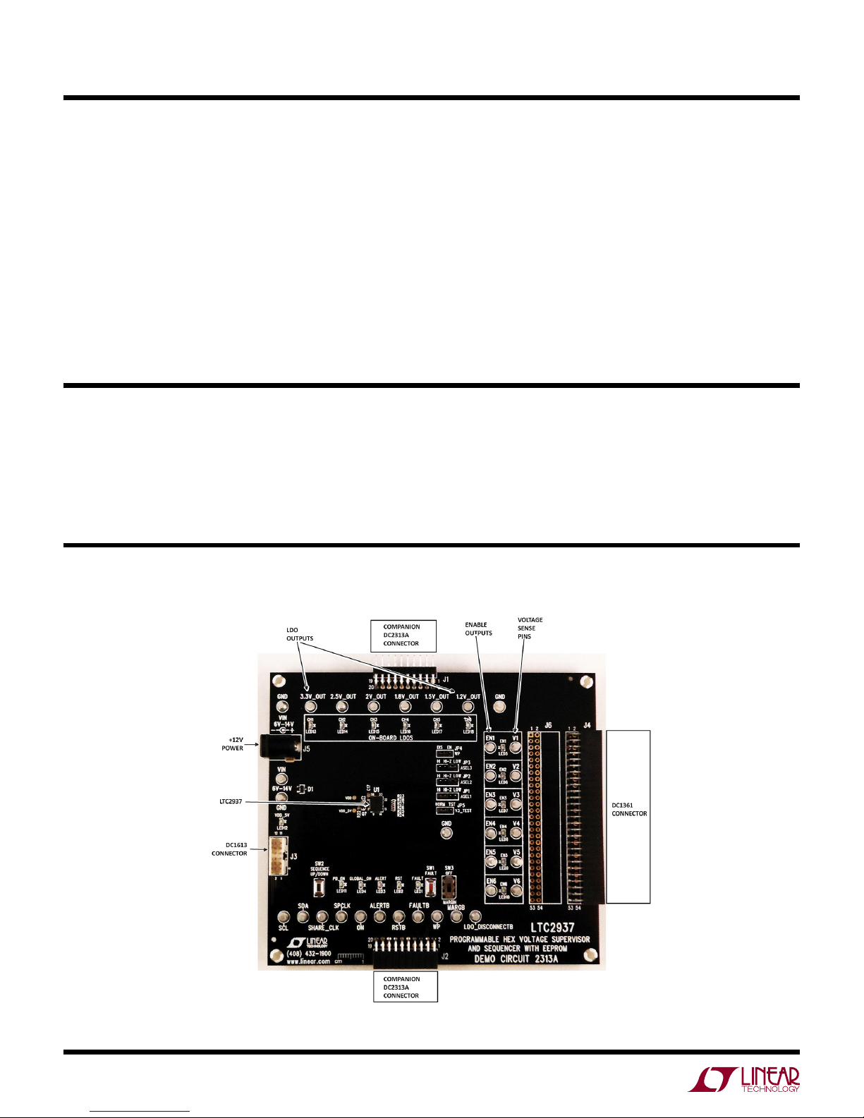
the Dc2313a BoarD
2
Figure 1. DC2313A Board
dc2313af
Page 3
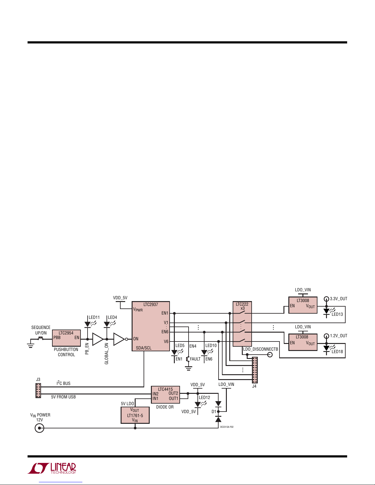
Dc2313 operating principLes
VDD_5V
V
PWR
ON
EN1
EN6
V1
V6
SDA/SCL
. . .
LTC2937
PBB
EN
LTC2954
IN1
OUT1
IN2
OUT2
LTC4415
LED4
LED11
D1
V
OUT
V
IN
LT1761-5
V
OUT
EN
LT3008
V
OUT
EN
LT3008
LTC222
x3
LED12
LED5
LED10J3SEQUENCE
UP/DN
VIN POWER
12V
J4
LDO_DISCONNECTB
LDO_VIN
3.3V_OUT
VDD_5V
LDO_VIN
I2C BUS
5V FROM USB
DC2313A F02
VDD_5V
EN1
FAULT
EN6
EN4
5V LDO
DIODE OR
...
...
PUSHBUTTON
CONTROL
LDO_VIN
LED13
1.2V_OUT
LED18
DEMO MANUAL DC2313A
The DC2313A board is fully functional as a stand-alone
evaluation platform for the LTC2937, and does not require
any external connections, other than power. It provides
convenient access to all of the LTC2937 pins through
turrets on the board, and basic control over the part by
jumpers and pushbuttons. Connectors can attach to ex
ternal devices for system prototyping. The board has six
LDO regulators that respond to control from the LTC2937,
and demonstrate its capabilities.
Additional functionality is accessible using the DC1613
2
USB-to-I
C “dongle” and LTpowerPlay software running on
a PC. The software provides a detailed view of the functions
of the LTC2937, including powerful fault management and
debug capabilities.
POWERING
The DC2313 can draw power from one of two sources.
Either 5V from the DC1613 ribbon cable connected to J3, or
from the V
connector to 12V. The DC1613 can only supply
IN
100mA, so when the board draws power from 5V do not
load any of the LDO outputs, as this may overload the 5V
supply. 12V must be used when loading the LDO outputs.
Multiple DC2313A boards connected together
J2 share power through the connectors, so attach 12V
and
through J1
and the ribbon cable to one of multiple DC2313A boards.
Only connect power to one of the boards. When the external
DC1361 board is attached to connector J4, use 12V power.
CONFIGURATION
A key feature of the LTC2937 is its non-volatile memory (EE
PROM), and its
ability to power-up in the correct configuration
-
to autonomously sequence and supervise the power system.
The DC2313A comes pre-programmed with default settings
to demonstrate the sequencing and supervision capabilities
of the LTC2937. The board functions with no intervention
from LTpowerPlay or other software. The pre-programmed
settings on the board are not the factory default settings
for the LTC2937, but are intended to provide a useful dem
,
onstration platform
The LTC2937 communicates through the I
with observable timing relationships.
2
C bus on the J3
-
connector. Select a bus address by changing the jumpers
ASEL1, ASEL2, and ASEL3. Each jumper can select either
HI, Hi-Z, or LOW, and the three jumpers together select
one of 27 addresses for the device. Select a unique address
2
for each device on the I
C bus. If multiple DC2313 boards
are connected together, each must have its own unique
ASEL jumper setting. Each LTC2937 will always respond
to its global 7-bit address 0x36. See the addressing section
in the LTC2937 data sheet for a complete address table.
Figure 2. DC2313A Simplified Diagram
dc2313af
3
Page 4
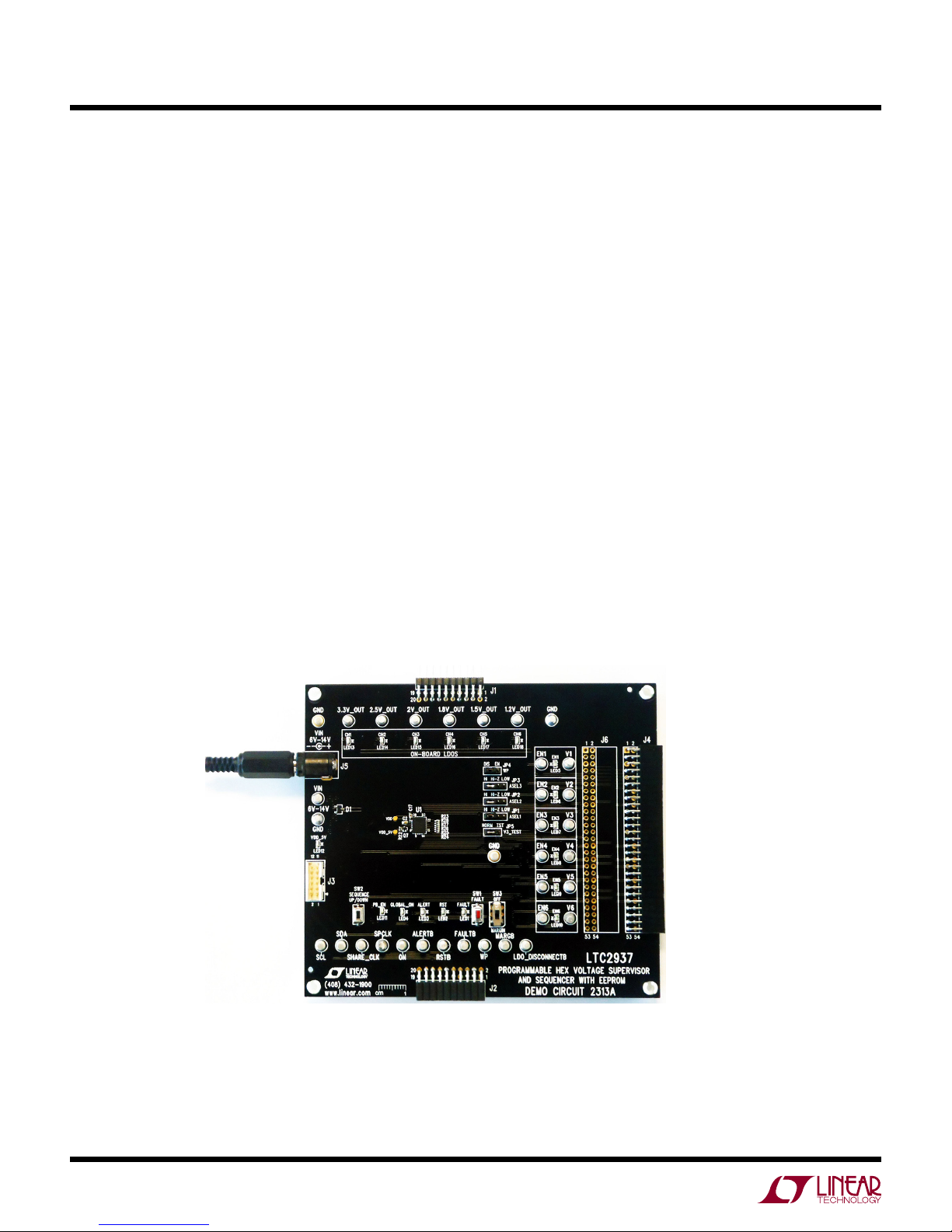
DEMO MANUAL DC2313A
Quick start proceDure (without software)
Begin exploring the basic features of the LTC2937 with
several exercises that do not require software. The following procedures
DC1613 connected, and no LTpowerPlay running. The board
will function autonomously without external software,
which is one of the important capabilities of the LTC2937.
SEQUENCING UP
Sequence up the supplies in an orderly fashion.
1) Apply power to the DC2313A by connecting 12V to the
J5 power connector.
The V
LEDs will be off.
2) Ensure that the SW3 switch is OFF, not in the MARGIN
position.
3) Press the “SEQUENCE UP/DOWN” pushbutton on the
DC2313.
assume a single DC2313A board with no
and RSTB LEDs will illuminate; all other
DD
The pushbutton is de-bounced by an LTC2954, which
requires sufficient time to register the button press
and activate the LTC2937 through the PB_ENB signal.
The PB_EN and GLOBAL_ON LEDs will illuminate.
The ENn LEDs will illuminate in sequence: 1-6.
The CHn LEDs will illuminate in sequence with the
ENn LEDs.
The RST LED will turn off when all supplies are within
their OV/UV limits (after the last CHn LED illuminates).
The FAULT
The ALERT LED will remain off.
The default voltage (UV and OV) limits and timing
parameters should not detect faults.
The DC2313A is programmed to provide human eye
observable sequence-up timing so that the time between
supplies powering-up is easily observable via LEDs. The
actual LTC2937 in-system sequence of events, and the
delays between events are all configurable.
LED will remain off.
4
Figure 3. DC2313A Standalone
dc2313af
Page 5

DEMO MANUAL DC2313A
Quick start proceDure (without software)
SEQUENCING DOWN
Bring down the supplies in an orderly fashion.
1) Begin with the system sequenced-up. The LDOs are on.
2) Press the “SEQUENCE UP/DOWN” pushbutton on the
DC2313.
The PB_EN and GLOBAL_ON LEDs will turn off.
The ENn LEDs will turn off in sequence: 6-1.
The CHn LEDs will turn off in sequence with the ENn
LEDs.
The RST LED will illuminate as soon as the CH6 LED
goes off.
The FAULT LED will remain off.
The ALERT LED will remain off.
The default voltage (UV and OV) limits and timing
parameters should not detect faults.
Notice that the sequence-down order of events is the reverse
of the sequence-up order. Channels can be reconfigured
easily via register programming to sequence-up and
sequence-down in any order, and sequence-down order
is independent of sequence-up order. As with sequencingup, the human-friendly, eye-observable sequence timing
is easily changed through register configuration.
AUTONOMOUS FAULT HANDLING
A fault is any condition that should not exist in the
system. The flexible LTC2937 is capable of autonomously
recognizing and handling faults without software
intervention. The LTC2937
SUPERVISOR fault, SEQUENCE fault, CONTROL fault,
EXTERNAL fault, and SHARE_CLK fault. We address
SUPERVISOR and SEQUENCE faults here. For more in
formation refer
examples, do not use software, or user/external interven-
recover from the fault condition. The LTC2937 is
tion to
programmed to recover on its own.
Note
that the LTC2937 ALERT pin requires a bus response
to de-assert once it asserts low. When using the LTC2937
in fully autonomous mode, we ignore the ALERT pin, and
to the LTC2937 data sheet. The following
recognizes 5 types
of faults:
-
the ALERT LED on the board. Once it is asserted, ALERTB
will remain asserted, and the ALERT LED illuminated. This
is harmless.
Supervisor Fault
A SUPERVISOR fault is caused by overvoltage (OV) detec
tion during sequence-up, or by OV or undervoltage (UV)
detection during normal operation (after a successful
sequence-up). In this demo configuration the LTC2937
automatically detects the fault and re-starts all of the
regulators.
Create this type of fault on the DC2313A board by pressing
the FAULT pushbutton, which momentarily pulls down the
EN4 line to GND, while in the sequenced-up state. This
will briefly disable and bring down the
create a UV condition. The LTC2937 will recognize the low
voltage and signal a SUPERVISOR fault.
1) Start with the system sequenced-up. The LDOs are on.
2) Press and release the FAULT pushbutton. This shorts
EN4 to GND, disabling the 1.8V LDO.
3) Observe the fault response:
All ENn pins pull low immediately. All ENn LEDs turn
off.
All of the LDO regulated supplies turn off immediately.
All CHn LEDs turn off.
The LTC2937 is configured to automatically re-try
after the fault, so it will attempt to sequence-up the
supplies. Since the fault was momentary, the resequence will succeed.
Pin FAULTB will assert low until the fault retry interval
is complete and the re-sequencing begins. The FAULT
LED will illuminate during this interval.
Pin RSTB will assert low until the LDOs come-up
after re-sequencing. The RST LED will illuminate
during this interval.
Pin ALERTB will assert low. The ALERT LED will
illuminate. The alert state will remain until an alert
response or a read from the CLEAR_ALERTB (0x28)
comes from the I
release the ALERTB pin.
2
C bus. Only a bus operation can
associated LDO
and
dc2313af
-
5
Page 6

DEMO MANUAL DC2313A
Quick start proceDure (without software)
The LTC2937 monitors each channel for individuallyprogrammed overvoltage and undervoltage thresholds.
The voltage monitoring is active while the supplies are
up or sequencing-up.
The LTC2937 is configured to re-try after the fault; it will
attempt to sequence-up again. There is a rich suite of fault
response capabilities in the part, including turning off and
staying off, turning-off then re-sequencing, continuing
operation without turning off, or entering a debug mode.
More details are available later in this manual, and in the
LTC2937 data sheet.
The FAULT indicators are self-clearing upon a re-sequence
initiation. The only fault indications after a successful
re-sequence-up are the asserted ALERTB pin, and the
EEPROM record of the first fault condition after the most
recent power-up that produced the fault. The ALERTB
pin will remain asserted low until the ALERT condition is
cleared with an I
Sequence Fault
A SEQUENCE fault is caused by supplies failing to meet
programmed voltage thresholds within programmed time
allowances during sequencing (for example, not ramping
fast enough).
Create this type of fault on the DC2313A board by pulling
and holding down one of the ENn
sequencing-up
sociated LDO
LTC2937 will recognize the unresponsive LDO and signal
a fault.
1) Start with the system sequenced-down. The LDOs are
off.
2) Short turret EN4 to GND and hold it there (press and
hold the FAULT pushbutton).
3) Press the “SEQUENCE UP/DOWN” button to initiate a
sequence-up operation.
EN1 - EN3 go high in sequence
CH1 - CH3 start in response to EN1-EN3
CH4 fails to start. LEDs EN4-6, CH4-6 remain off.
4) Observe the repeated fault retry response (see the table)
2
C bus operation.
turrets to GND while
the supplies. This will hold down the as-
and create a permanent UV condition. The
Pins EN1 - EN3 pull low immediately. All illuminated
ENn LEDs turn off.
All of the LDO regulated supplies turn off. Illuminated
CHn LEDs turn off.
The LTC2937 is configured to automatically re-try
after a delay, so it will attempt to sequence-up the
supplies after detecting the fault. Since the LDO is
shorted, the fault persists, and re-sequencing will
repeatedly fail. The cycle will repeat until the fault is
removed (by releasing the FAULT pushbutton).
Pin FAULTB will assert low for the retry interval,
re-sequence begins. LED FAULT will illuminate
the
during the interval.
The FAULTB pin clears as soon as a re-sequence
begins. The FAULT LED illuminates briefly, then goes
off.
Pin RSTB will remain low. The RST LED will remain
illuminated because not all of the supplies ever come
up.
Pin ALERTB will assert low. The ALERT LED will
illuminate. The alert state will persist until an alert
response or a read from the CLEAR_ALERTB (0x28)
comes from the I
release the ALERTB pin.
5) Remove the EN4 fault by releasing the FAULT pushbut
ton.
6) Observe that the part completes the re-sequence autonomously, and
The RST LED goes off after all supplies are up.
Each channel has an independently-configurable time limit
for starting-up and rising above its UV threshold voltage.
Each channel also has independently-programmable
sequence-down time parameters.
The LTC2937 is configured by default in the FAULT_RE
SPONSE (0x23) register
after all of the supplies are disabled and the voltages fall
below their discharge thresholds. While the EN4 pin is held
the fault persists, and the LTC2937 is programmed
low,
to automatically try to re-sequence the supplies forever,
so the behavior will repeat indefinitely.
2
C bus. Only a bus operation can
the
fault response clears automatically.
to automatically re-sequence-up
until
dc2313af
-
-
6
Page 7

DEMO MANUAL DC2313A
Quick start proceDure (without software)
After the fault goes away the next automatic re-sequence
will succeed. The FAULTB pin will de-assert. The FAULT
LED will go off. Initiation of the next sequence-up operation
will clear the fault information in registers. The ALERTB
pin will remain asserted low until the ALERT condition is
cleared with an I
Margining The Supplies
Margin testing stresses the system by moving voltages
beyond their normal OV and UV limits without generating
a fault. The MARGIN switch on the DC2313A board pulls
down the MARGB pin on the LTC2937, causing it to ignore
OV and UV faults while in the sequenced-up state. Note
that the LTC2937 does not control the voltages. Margining
the supplies involves pulling the regulators to out-of-spec
voltages, which is done outside of the LTC2937. The LDO
regulators on the DC2313A board do not change voltage,
but we can demonstrate MARGIN capability while disabling
one of the LDOs.
1) Begin with the system sequenced-down (all supplies
OFF)
While the supplies are down, the RST LED is illumi
nated.
Switch SW3 to the MARGIN position (MARGIN active).
2)
Observe the RST LED goes
LTC2937 is ignoring the UV conditions.
2
C bus operation.
-
off, indicating that the
3)
Press the “SEQUENCE UP/DOWN” pushbutton to
sequence-up normally.
The PB_EN and GLOBAL_ON LEDs will illuminate.
The ENn LEDs will illuminate in sequence: 1-6.
The CHn LEDs will illuminate in sequence with the
ENn LEDs.
The RST LED will remain off because the MARGIN
function is active.
The FAULT LED will remain off.
The ALERT LED will remain off.
No voltage (UV and OV) limits are measured. The
default timing parameters should not detect faults.
4) While the MARGIN switch is active, short the EN4 turret
to GND by pressing the FAULT pushbutton.
The corresponding CH4 will go down and the LED
will go off.
No faults are detected due to the MARGIN function.
Note that the MARGIN function is only useful while the
supplies are sequenced-up, not while they are in the process
of sequencing. Holding the MARGB pin asserted low does
not mask SEQUENCE (timing) faults during sequencingup operations. If a supply fails to meet its programmed
sequence-up voltage/timing requirements then the normal
fault response prevails, regardless of MARGB state.
software controL with LtpowerpLay
LTpowerPlay is a convenient PC
complete
other Linear Technology Power System Management parts.
Use it in off-line mode to build a system configuration file,
even with no hardware plugged-in, and use it with hard
ware connected
LTpowerPlay communicates using the I
system (covered in this manual), or in your real-world
product environment. It provides unprecedented control
over the Linear Technology chips on the I
access to the registers of the LTC2937, and many
to configure and debug your application.
software GUI that gives
2
C bus in the demo
2
C bus. Use it
during board bring-up to tune and optimize the power
system parameters. Use it during system debug to view
critical system information and troubleshoot board design
or manufacturing issues. LTpowerPlay includes extensive
-
help and documentation under the Help menu. On-line
help includes quick-start videos and tutorials, and detailed
technical documentation from the Linear Technology web
site. Getting started with LTpowerPlay is easy. Simply
download and install the PC software from here:
http://www.linear.com/ltpowerplay
dc2313af
7
Page 8
DEMO MANUAL DC2313A
software controL with LtpowerpLay
To the right of the system tree is the Configuration Register
pane, displaying all of the configuration registers available on
writable
offers clickable buttons and fields to edit the information
in these registers.
the selected device. This view shows all of the
LTpowerPlay System Tree
user-configurable RAM registers, and the GUI
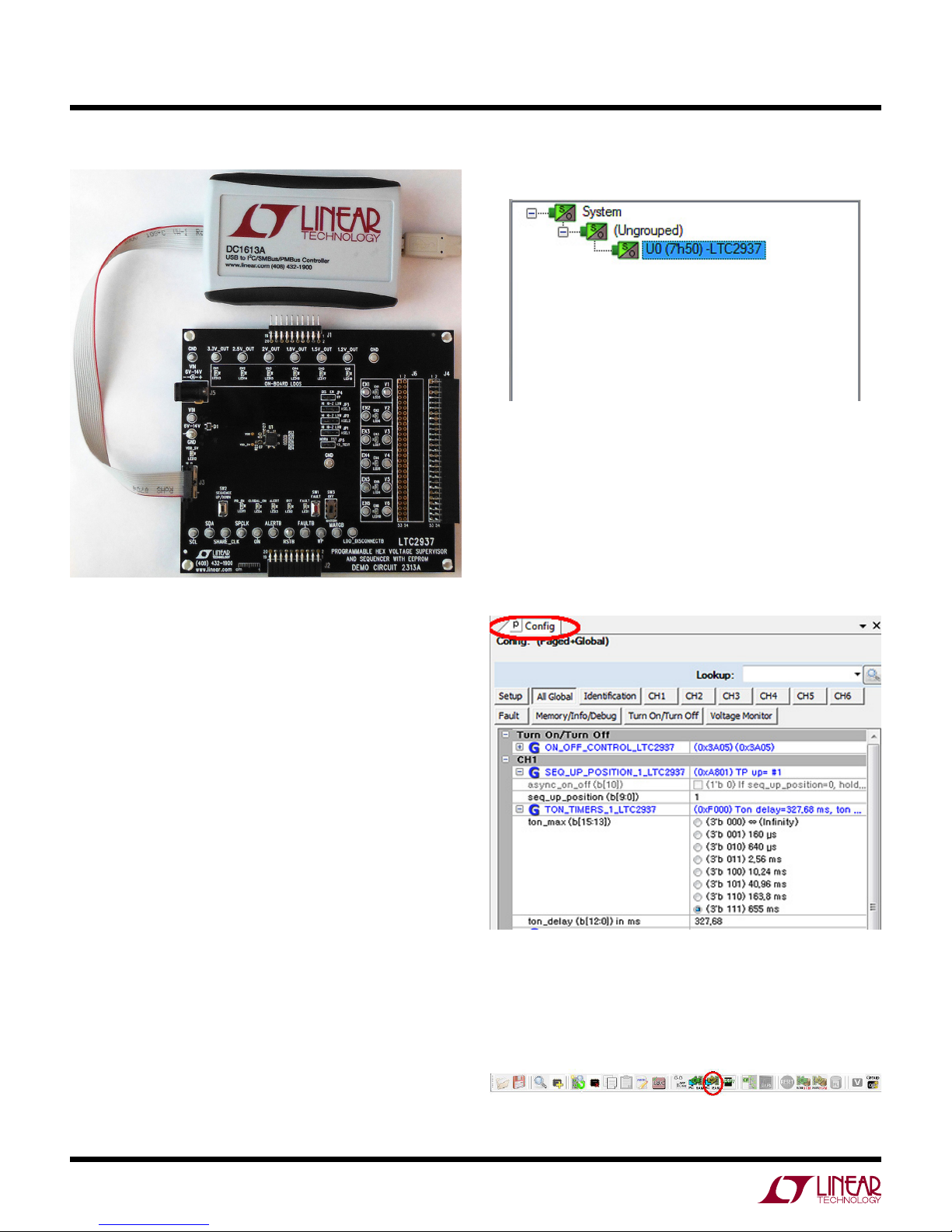
Figure 4. DC2313A Demo Board Connected
to DC1613A I2C-to-USB Converter
The DC1613 USB-to-I2C adapter interfaces the PC running
LTpowerPlay to the DC2313A board (or any board with an
2
C bus). Connect the DC1613 adapter to the PC through a
I
USB cable, and connect it to the DC2313A board through
the ribbon cable to connector J3.
Launch the LTpowerPlay GUI on the PC. The software
identifies the DC1613 controller, then the DC2313A board,
and begins communicating through the I
LTC2937. Once this communication has been established,
the GUI displays its main window (Figure 5).
The LTpowerPlay GUI divides information into separate
panes in the window. On the left is the System Tree pane,
displaying a list of all Linear Technology devices identified
on the I
small, but if other supported devices are present on the
2
I
this list to selectively access it. Information in other panes
pertains to the selected device.
2
C bus. For a single LTC2937 device, the tree is
C bus, LTpowerPlay will add them. Click on a device in
2
C bus with the
LTpowerPlay Configuration Registers
Update register contents by clicking or typing to change
the desired registers, then selecting the “Write All” but-
the top toolbar. LTpowerPlay writes changes to the
ton in
updated registers.
8
dc2313af
Page 9

DEMO MANUAL DC2313A
software controL with LtpowerpLay
Figure 5. LTpowerPlay GUI Window
Note that programming the registers in the LTC2937 should
generally be done while the part is in the sequenced-down
state. Most of the registers have immediate control over
their respective chip functions, and changing them while
the part is sequenced-up will have unpredictable and ad
. It is
verse effects
updating configuration register settings. LTpowerPlay
implements limits to writing some registers, based upon
the device state, and will pop-up warnings when necessary.
Right of center in LTpowerPlay is the Telemetry pane,
displaying read-only information contained in the status
registers of the selected part. The GUI periodically polls
2
C bus and updates the Telemetry contents in real
the I
time, along with a user-friendly interpretation of the bits.
recommended to sequence-down before
-
LTpowerPlay Telemetry
dc2313af
9
Page 10

DEMO MANUAL DC2313A
software controL with LtpowerpLay
In the upper right corner of LTpowerPlay is the Chip
Dashboard pane, displaying a graphical representation of
the part status in a friendly, easy-to-understand format.
The live channel voltage comparator OV and UV states are
shown in the “Comparator Status”. The sequencing state
is represented in the “Sequencing” block. Fault status is
summarized in the “Fault Summary” block. Other status
bits are represented by light-up red-yellow-green indica
tors on
the part status at-a-glance.
the right-hand side. These intuitive indicators give
LTpowerPlay Chip Dashboard
-
The LTC2937 features an EEPROM non-volatile memory
that holds device configuration information and a snapshot
of past fault information. When the part receives power
it executes a power-on reset, and restores the contents
of the EEPROM to its operating RAM memory. Following
this power-on restore, operating RAM memory can be
modified with I
behavior. This modified state can be stored to the EEPROM
with a STORE (0x2C) command, making it available as the
future default power-up state. The STORE command will
copy the entire contents of the configuration RAM into
EEPROM. The data sheet recommends storing EEPROM
contents only while the part is sequenced-down.
In addition to power-on reset, the EEPROM contents can
also be retrieved to RAM operating memory with a RE
STORE (0x2D) command. RESTORE wipes-out the content
of the RAM and replaces it with the EEPROM contents.
Only perform a RESTORE when the LTC2937 is in the
sequenced-down state, as the RAM operating memory
immediately affects the chip, and changing its contents
while sequenced-up can result in unpredictable behavior.
2
C bus commands that modify the part
-
LTC2937 REGISTERS
LTC2937 RAM and Non-Volatile Memory
The LTC2937 is highly configurable through its register
set. Refer to the LTC2937 data sheet for a complete
discussion of the registers and functions available. Get
immediate access to detailed help for the selected register
in LTpowerPlay by pressing the F1 key on your keyboard.
Both RAM and EEPROM respect write-protection on the
LTC2937. Both the
(0x00) register provide write protection. Configure both the
pin and the register to allow writing to memory. To enable
writing, pull the hardware WP pin to ground by setting
jumper JP4 to DIS. Write the command 0x00 with bit 0 = 0,
and the same key that is in WRITE_PROTECTION[15:2]. The
demo board default for the WRITE_PROTECTION register
and the WP pin allow writing to memory.
The following exercises approach the registers in a task-
oriented manner, demonstrating register functions through
examples.
Default Configuration
If the LTC2937 EEPROM contains non-default contents,
then returning it to the demo-board default settings can
be accomplished with the LTpowerPlay “Demo” menu
selection.
WP pin and the WRITE_PROTECTION
10
dc2313af
Page 11

DEMO MANUAL DC2313A
software controL with LtpowerpLay
Clicking the “Demoboard Defaults” menu item stores
default register settings in RAM, issues a CLEAR command, then
contents
into its default setting for the demo board. Note that this
procedure only works if the ASEL jumpers are configured
in their default settings:
ASEL1 = HI
ASEL2 = HI
ASEL3 = HI
ON/OFF CONTROL
The LTC2937 provides control over all of its functions
through the register interface. This includes ON/OFF con
trol. The
to
a register ON/OFF bit, or to both. In this exercise, we
will sequence the system up and down using the I
command, ignoring the hardware ON/OFF pin. To program
the part to turn on and off through the I
executes a STORE command to store the RAM
into EEPROM. This places the LTC2937 back
part can respond to the hardware ON/OFF pin, or
2
C bus
2
C bus:
-
The supplies sequence-up normally
4)
The ENn LEDs will illuminate in sequence: 1-6.
The CHn LEDs will illuminate in sequence with the
ENn LEDs.
The RST LED will turn off after the last CHn LED
illuminates.
The LTC2937 Chip Dashboard in LTpowerPlay
tracks the internal register status in real time as it
sequences-up.
1) Start with the part sequenced-down (PB_EN LED is off,
LDOs are off).
2) Program register ON_OFF_CONTROL (0x02) by clicking
the checkboxes for each bit to sequence-up via the I
bus:
b[2] = 0 (ignore the ON input pin)
b[3] = 1 (honor the software ON/OFF bit)
b[4] = 1 (software ON
3) Send the register updates from LTpowerPlay to the
LTC2937 by pressing the Write All Button:
/OFF state is ON)
2
C
In the LTC2937 internal registers:
The ON_OFF_CONTROL[7] bit becomes set, indicat
ing that the part is commanded to sequence-up.
The STATUS_INFORMATION[11:10] bits cycle
through the sequence-up states:
00b : sequence-down complete
01b : sequence-up in-progress
11b : sequence-up complete
The SEQ_POSITION_COUNT[9:0] bits count through
the sequence-up states (1 – 7).
The FAULT LED will remain off.
The ALERT LED will remain off.
The PB_EN and GLOBAL_ON LEDs will remain off.
The ON pin is low.
The default voltage (UV and OV) limits and timing
parameters should not detect faults.
-
dc2313af
11
Page 12

DEMO MANUAL DC2313A
software controL with LtpowerpLay
5) Setting register bit ON_OFF_CONTROL[4] = 0
commands the part to sequence-down. All sequence
timing and voltage limits apply. Click the i2c_on_off
(b[4]) checkbox and hit ‘F12’ on the keyboard to update
the register in the LTC2937.
The ENn LEDs will turn off in sequence: 6-1.
The CHn LEDs will turn off in sequence with the ENn
LEDs.
The RST LED will illuminate after the first CH6 LED
turns off.
The ON_OFF_CONTROL[7] bit becomes low, indicating
that the part is commanded to sequence-down.
Restore the EEPROM default register settings by execut
ing a RESTORE (0x2D) command. In LTpowerPlay this
command
followed by the read RAM registers button:
SUPPLY SEQUENCE ORDER
The LTC2937 provides complete sequence order and timing
control over enabling and disabling
supplies
to go down in any (different) order. The LTC2937 provides
up to 1023 ordered sequence positions in which events
can be scheduled during sequence-up and sequence-down.
Each supply has its own SEQ_UP_POSITION_n register
(0x16 – 0x1B) and SEQ_DOWN_POSITION_n register
(0x1C – 0x21). In the demo-board default settings, the
supplies sequence-up in the order 1-6, and sequencedown in the order 6-1. We can change this ordering by
writing to the registers:
is issued by pressing the RESTORE button,
the supplies. Sequenced
can be commanded to come-up in any order, and
-
The STATUS_INFORMATION[11:10] bits cycle through
the sequence-down states:
11b : sequence-up complete
10b : sequence-down in-progress
00b : sequence-down complete
The SEQ_POSITION_COUNT[9:0] bits count through
the sequence-down states (1 – 7).
The FAULT LED will remain off.
The ALERT LED will remain off.
The PB_EN and GLOBAL_ON LEDs will remain off. The
ON pin is low.
The default voltage (UV and OV) limits and timing
parameters should not detect faults.
This procedure is equivalent to pressing the “SEQUENCE
UP/DOWN” pushbutton on the board to command a
sequence-up and sequence-down.
1) Begin with the LTC2937 in the sequenced-down state
(all supplies off).
2) Write each of the 6 SEQ_UP_POSITION_n registers to
change their sequence positions:
SEQ_UP_POSITION_1 = 0x0005 : place channel 1 in
sequence position 5
Do this by clicking on the “SEQ_UP_POSITION_1_
LT C2937” text, and typing 0x0805 then ENTER. This
updates the register value in the GUI.
You may also click on “seq_up_position (b[9:0])” and
typing “5” ENTER. Notice that the hex value updates
as a result.
12
dc2313af
Page 13

DEMO MANUAL DC2313A
software controL with LtpowerpLay
4) If you have not already written the GUI configuration
to RAM (using F12), then update all registers with the
Write All button
5) Initiate a sequence-up by writing ON_OFF_CONTROL[4:2] = 110.
After modifying a register hit F12 on the keyboard to
update that register in the LTC2937 RAM.
Continue with the other channels:
SEQ_UP_POSITION_2 = 0x0007 : place channel 2 in
sequence position 7
SEQ_UP_POSITION_3 = 0x0003 : place channel 3 in
sequence position 3
SEQ_UP_POSITION_4 = 0x0001 : place channel 4 in
sequence position 1
SEQ_UP_POSITION_5 = 0x0002 : place channel 5 in
sequence position 2
SEQ_UP_POSITION_6 = 0x0004 : place channel 6 in
sequence position 4
3) Write each of the 6 SEQUENCE_DOWN_POSITION_n
registers to change their sequence positions:
SEQ_DOWN_POSITION_1 = 0x0001 : place channel 1
in sequence position 1
SEQ_DOWN_POSITION_2 = 0x0001 : place channel 2
in sequence position 1
SEQ_DOWN_POSITION_3 = 0x0007 : place channel 3
in sequence position 7
SEQ_DOWN_POSITION_4 = 0x0003 : place channel 4
in sequence position 3
Remember that we are programmed to ignore the
SEQUENCE UP/DOWN pushbutton.
6) Observe the modified sequence-up order as the sup
plies come up.
The ON_OFF_CONTROL[7] bit becomes set
The STATUS_INFORMATION[11:10] bits cycle
through the sequence-up states
The SEQ_POSITION_COUNT[9:0] bits count through
the sequence-up states (1-8).
7) Initiate a sequence-down by writing ON_OFF_CON
TROL[4:2] = 010.
The SEQ_POSITION_COUNT[9:0] bits count through
the sequence-down states (1-1023-0).
Notice that channel 5 is in the last sequence-down
position (1023). During sequence-down operation
the SEQUENCE POSITION COUNT will count up to
1023 before de-activating EN5, then roll-over to count
0 before stopping.
Restore the EEPROM default register settings by
executing a RESTORE (0x2D) command. In LT
powerPlay this
RESTORE button, followed by the read RAM registers
button:
command is issued by pressing the
-
-
-
SEQ_DOWN_POSITION_5 = 0x03FF : place channel 5
in sequence position 1023
SEQ_DOWN_POSITION_6 = 0x0004 : place channel 6
in sequence position 4
dc2313af
13
Page 14

DEMO MANUAL DC2313A
software controL with LtpowerpLay
Each supply can occupy any one of the 1023 available
sequence positions. Multiple supplies can occupy the same
sequence position – for example, they could all occupy
sequence position 3. Unused sequence positions take a
minimal amount of time (80µs) to complete, but do not
trigger any enable or disable events. The part continues
counting until the last used sequence position, plus one.
Within each sequence position, additional flexibility is
available for enable and disable timing of each supply
using the ton_delay and toff_delay settings. Each supply
can delay up to 655ms from the start of its sequence
position before enabling (TON_TIMERS[12:0]) or disabling
(TOFF_TIMERS[12:0]). This provides deterministic timing
relationships between supplies within a sequence position.
The sequence position clock waits for all scheduled sup
plies in that position. These behaviors are best observed
with a scope, since the time resolution is microseconds
– much faster than the eye can observe the LEDs on the
board sequencing.
Further flexibility is available if multiple LTC2937s
sequence many supplies. The LTC2937 parts communicate
through the SPCLK and SHARE_CLK signals so that
they maintain a common sequence count and timebase,
and a large number of supplies
autonomously
SEQ_UP_POSITION, SEQ_DOWN_POSTION, ton_delay,
and toff_delay registers to freely interleave supplies across
multiple LTC2937s.
coordinated, deterministic manner. Use the
can be sequenced in an
-
Try Count
Re-
In the DC2313 demo board the LTC2937 is configured
to re-try an unlimited number of times when it detects
a SUPERVISOR or SEQUENCE fault. It can instead be
configured to respond in a limited way to a fault, and
give-up if the problem persists. The number of re-try
attempts can be set with the FAULT_RESPONSE[2:0]
register bits (retry_number). Any number of attempts can
be specified, from 0 to 6, or unlimited. The
to a SUPERVISOR or SEQUENCE fault by turning-off the
supplies, then trying to sequence-up. It will register the
number of attempts in the FAULT_RESPONSE[13:11] bits,
and stay off after failing the specified number of times.
Fault Debug
In this exercise set the fault response to zero automatic
re-tries, which will enable debugging. Create a fault on the
DC2313A board with the FAULT pushbutton.
1) Start with the system sequenced-down. The LDOs are
off.
2) Set FAULT_RESPONSE[2:0] = 0x0. This sets zero re-try
attempts after a fault.
part will
respond
FAULT RESPONSE
To this point, the demonstrations have shown the LTC2937
responding to faults by autonomously re-starting the
supplies without software. This important behavior is
only one of the possible choices, however. The LTC2937
provides a rich and configurable set of fault response
capabilities allowing either an autonomous recovery, an
2
C bus mediated response, or a completely interactive
I
software debugging experience.
The LTC2937 data sheet details all of the fault-response
registers, and the various programming options for han
dling faults, and debugging behaviors. Below are several
examples.
14
-
dc2313af
Page 15

DEMO MANUAL DC2313A
software controL with LtpowerpLay
3) Press the “SEQUENCE UP/DOWN” pushbutton and
wait for sequence-up to complete.
4) Press and release the FAULT pushbutton, momentarily
shorting EN4 to GND and bringing down the 1.8V LDO.
The LTC2937 immediately recognizes the low V4 voltage.
5) Observe the fault response
All ENn pins pull low immediately. All ENn LEDs
turn off.
All of the LDO regulated supplies turn off immediately.
All Chn LEDs turn off.
The fault response setting allows no re-try attempts,
so the supplies remain off.
Pin FAULTB will assert and remain low. LED FAULT
will illuminate.
Pin RSTB will assert low. LED RST will illuminate.
Pin ALERTB will assert low. LED ALERT will illuminate.
The alert state will remain until an alert response or
a read from the CLEAR_ALERTB (0x28) comes from
2
C bus.
the I
Register MONITOR_STATUS (0x30) will briefly report
the real time UV comparator assertion until the fault
goes away when the FAULT button is released.
Register MONITOR_STATUS_HISTORY (0x26) will
report the latched SUPERVISOR UV fault condition.
This information remains because the LTC2937 does
not re-sequence.
The LTpowerPlay Chip Dashboard shows the summary
of fault information. This conveniently indicates that the
part has detected a SUPERVISOR UV fault, and that fault
information is stored in the EEPROM MONITOR_BACKUP
register.
Note that the V4 dial has a double red arc, indicating that
the V4 channel caused the UV fault that brought-down
the system.
Notice that ALL status information is retained in the
state it was in when the fault occurred. This includes the
sequencer state (SP=7, Syst=UP, Chip=UP). The STATUS_
INFORMATION[11:10] and STATUS_INFORMATION[9:8]
were in the “sequence-up complete” state when the fault
occurred, so these states are retained. The state machine
still thinks it is in the same state.
Register STATUS_INFORMATION (0x29) will report
the latched SUPERVISOR UV fault condition.
Register MONITOR
MONITOR_STATUS_HISTORY register contents, but
only if this is the first fault since power applied. If this
is not the first fault, MONITOR_BACKUP will contain
older fault information. Execute a RESTORE command
to view the MONITOR_BACKUP register contents.
The LTC2937 does not attempt to recover from the fault.
Instead, it turns-off all of the supplies and retains all of
its status register contents. This enables a thorough postfault examination of status registers in the state they were
when the fault occurred.
_BACKUP in
EEPROM will mirror
dc2313af
15
Page 16

DEMO MANUAL DC2313A
software controL with LtpowerpLay
Status register contents are cleared when the LTC2937
begins a new sequence-up operation, so allowing auto-
-try
matic re
that might exist in the registers.
The only fault information that will persist beyond a
successful re-sequence initiation is in the EEPROM
MONITOR_BACKUP register, which stores the contents
of the MONITOR_STATUS_HISTORY register when the
first fault after power-up is detected.
The ALERTB pin will remain asserted low until the ALERT
condition is cleared with an I
Recovering from and Clearing Faults
The FAULTB pin and status registers respond to a fault
condition, but can be cleared when the LTC2937 resequences the power supplies. Along with the status
information registers, the FAULTB pin is cleared when the
sequence starts. In the case where fault information and
the FAULTB pin need to be cleared manually, the CLEAR
(0x2E) command is available.
after a fault eliminates the debug information
2
C bus (ARA) operation.
Clearing the ALERTB Pin
The ALERTB pin conforms to the SMBus protocol for
the SMBALERT fault response. It is designed to act as
an interrupt for a controller on the I
ALERTB pin asserts when a fault event occurs, and it can
only be cleared by an appropriate bus response from the
controller.
When the ALERTB pin asserts, a controller may either
execute an alert response through the Alert Response
Address (0x0C), which is a defined as the ARA in the
SMBus protocol, or the controller may read from register
CLEAR_ALERTB (0x28) to immediately de-activate the
ALERTB pin.
LTpowerPlay will include the CLEAR_ALERTB command
when sending a CLEAR_FAULTS command if the behavior
is selected in the Preferences menu. Pull-down View→
Preferences…, then select “Issue CLEAR_ALERTB on
CLEAR” = TRUE. When you click the CLEAR_FAULTS
button in the GUI it will also clear ALERTB.
2
C bus. The LTC2937
LTpowerPlay allows the user to issue the CLEAR command
(0x2E) that clears the fault and status registers. Issue the
CLEAR command by pressing the “CLEAR” button in the
toolbar:
Warning: avoid issuing a CLEAR command while the
LTC2937 is in the sequenced-up state. The registers and
state-machines that get cleared have an immediate ef
fect on the part, and will cause the supplies to fault and
re-sequence, which is usually an undesired behavior.
Sequence-down before issuing a CLEAR command.
If the LTC2937 is waiting, not re-trying, after a fault, turn
it off (press the “SEQUENCE UP/DOWN” button to turnoff the PB_EN and GLOBAL_ON LEDs). The LTC2937 will
retain state, but will be ready to sequence-up. Press the
“SEQUENCE UP/DOWN” button again to sequence-up
normally and clear the latched fault status and the FAULTB
pin. The ALERT pin will remain asserted until cleared.
-
16
dc2313af
Page 17

DEMO MANUAL DC2313A
software controL with LtpowerpLay
EEPROM Fault Backup
The LTC2937 stores information about the “first” fault that it
detects into the EEPROM MONITOR_BACKUP register. The
information is a copy of the MONITOR_STATUS_HISTORY
register at the time of the fault. Subsequent power-cycling
has no effect on this stored information, which can be
read with the MONITOR_BACKUP command (0x2F)
after a RESTORE, or a after a power-cycle. This debug
information survives subsequent sequencing operations,
and power cycling. Only the first fault information is stored
in EEPROM. The indicator bit, STATUS_INFORMATION[12]
holds a persistent 1 if the MONITOR_BACKUP register
contains a fault record.
Re-arm the MONITOR_BACKUP register to accept a new
“first” fault by clearing it according to this recipe:
1) Begin in the sequenced-down state. The supplies are
off. The register STATUS_INFORMATION[11:8] = 0x0.
2) Issue a CLEAR command (0x2E) by pressing the “CF”
button in LTpowerPlay. This clears any fault information,
including MONITOR_STATUS_HISTORY.
4) Issue a RESTORE command (0x2D). This restores
the clean MONITOR_BACKUP register contents from
EEPROM. It clears the STATUS_INFORMATION[12]
indicator bit. It also restores all configuration registers
from EEPROM.
Note that it is important to perform the CLEAR and RE
(
STORE operations
sequencing-down. The internal sequencing state machine
receives a reset when the CLEAR command is issued. If the
LTC2937 is sequenced-up, or in the process of sequenc
ing, this reset will generate a fault, possibly turn off the
supplies, and re-sequence-up.
be aware that the STORE command affects the entire
Also
EEPROM, not only the MONITOR_STATUS_HISTORY
word. This means that any changes that have been made to
the RAM configuration registers will be stored in EEPROM.
Also, if there is newer fault information in RAM than in
the first fault MONITOR_BACKUP register, it will be stored
into EEPROM with a STORE command.
in that order) while the part is finished
-
-
3) Issue a STORE command (0x2C). This stores the clean
MONITOR_STATUS_HISTORY register contents to
EEPROM. It also stores all configuration registers to
EEPROM.
dc2313af
17
Page 18

DEMO MANUAL DC2313A
Dc2313a BoarD Description
18
Figure 6. DC2313A Demo Board Layout
dc2313af
Page 19

DEMO MANUAL DC2313A
parts List
ITEM QTY REFERENCE PART DESCRIPTION MANUFACTURER/PART NUMBER
Required Circuit Components
1 4 C1, C7, C10, C17 CAP., 0.1µF, X5R, 16V, 10%, 0603 MURATA, GRM188R61C104KA01D
2 7 C2, C11-C16 CAP., 2.2µF, X5R, 10V, 10%, 0603 MURATA, GRM188R61A225KE34D
3 2 C3, C4 CAP., 0.01µF, X7R, 10V, 10%, 0603 AVX, 0603ZC103K AT2A
4 2 C5, C9 CAP., 10µF, X5R, 16V, 10%, 0805 MURATA, GRM21BR61C106KE15L
5 1 C6 CAP., 22µF, X5R, 25V, 20%, 0805 MURATA, GRM21BR61E226ME44K
6 1 C8 CAP., 1µF, X5R, 16V, 10%, 0603 MURATA, GRM188R61C105KA93D
7 1 D1 DIODE, Schottky, SOT23 VISHAY, BAS70-05-E3-08
8 34 E1-E34 TEST POINT, TURRET, .094" MTG. HOLE MILL-MAX, 2501-2-00-80-00-00-07-0
9 3 JP1, JP2, JP3
10 2 JP4, JP5
11 1 J1
12 1 J2
13 1 J3
14 1 J4
15 1 J5 CONN., POWER JACK, 2.1mm CUI INC., PJ-002AH
16 0 J6
17 2 LED1, LED3 LED, RED, 0603 PANASONIC, LNJ237W82RA
18 1 LED2 LED, AMBER, 0603 PANASONIC, LNJ426W83RA
19 15 LED4-LED18 LED
20
21 6 Q8-Q13 XSTR., NPN, SOT23 FAIRCHILD, MMBT3904
22 19 R1-R4, R6, R8, R10,
23 20 R5, R7, R9, R11, R13,
24 1 R20 RES., 374k, 1/16W, 1%, 0402 VISHAY, CRCW0402374KFKED
25 11 R27, R28, R32, R37,
26 1 R31 RES., 46.4k, 1/16W, 1%, 0402 VISHAY, CRCW040246K4FKED
27 1 R33 RES., 9.31k, 1/16W, 1%, 0402 VISHAY, CRCW04029K31FKED
28 1 R34 RES., 249, 1/16W, 1%, 0402 VISHAY, CRCW0402249RFKED
29 1 R35 RES., 1k, 1/16W, 1%, 0402 VISHAY, CRCW04021K00FKED
30 6 R43, R44, R50,
31 1 R49 RES., 1.37M, 1/16W, 1%, 0402 VISHAY, CRCW04021M37FKED
32 1 R51 RES., 590k, 1/16W, 1%, 0402 VISHAY, CRCW0402590KFKED
33 1 SW1 SWITCH, Push Button, SW-PTS635-25 C&K Components, PTS635SK25SMTR LFS
7 Q1-Q7 XSTR., MOSFET, N-CH, SOT523 DIODES INC., DMG1012T-7
R12, R14, R16, R18,
R23, R29, R39, R40,
R45, R46, R53, R54
R15, R17, R19, R21,
R22, R24-R26, R30,
R59-R64
R38, R41, R42, R47,
R48, R55, R56
R52, R57, R58
CONN., HEADER, 1×4, 2mm
CONN., HEADER, 1×3, 2mm
CONN., HEADER, 2×10, .100", R/A
CONN., SOCKET, 2×10, .100", R/A
CONN., HEADER, 2×6, 2mm, STR DL PCB
CONN., SOCKET, 2×27, .100", R/A
CONN., SOCKET, 2×27, .100", R/A
, GREEN, 0603 PANASONIC, LNJ326W83RA
RES., 3.01k, 1/10W, 1%, 0402 VISHAY, CRCW04023K01FKED
RES., 100k, 1/16W, 1%, 0402 VISHAY, CRCW0402100KFKED
RES., 10k, 1/16W, 1%, 0402 VISHAY, CRCW040210K0FKED
RES., 200k, 1/16W, 1%, 0402 VISHAY, CRCW0402200KFKED
SULLINS, NRPN041PAEN-RC
SULLINS, NRPN031PAEN-RC
MILL-MAX, 802-40-020-20-001000
MILL-MAX, 803-93-020-20-001000
FCI, 98414-G06-12ULF
SULLINS, PPTC272LJBN-RC
OPT
dc2313af
19
Page 20

DEMO MANUAL DC2313A
parts List
ITEM QTY REFERENCE PART DESCRIPTION MANUFACTURER/PART NUMBER
34 1 SW2 SWITCH, Push Button, SW-PTS635-25 C&K Components, PTS635SL25SMTR LFS
35 1 SW3 CONN, SUB MINIATURE SLIDE SWITCHES C&K.,JS202011CQN
36 1 U1
37 2 U2, U3 I.C., DUAL BUFFERS, TSOP-6 NXP, 74LVC 2G07GV,125
38 1 U4
39 1 U5 I.C., LINEAR REG - 5V, TSOT23-5 LINEAR TECH., LT1761ES5-5
40 1 U6 I.C., DIODE OR, MSE16 LINEAR TECH., LTC4415IMSE
41 3 U7, U8, U9 I.C ANALOG SWITCH, SO16 LINEAR TECH, LTC222CS
42 1 U10 I.C SERIAL EEPROM, TSSOP8 MICROCHIP, 24AA02-I /ST
43 1 U11
44 1 U12
45 1 U13
46 1 U14
47 1 U15
48 1 U16
49 5 SHUNTS ON JP1-JP5
PINS 1&2
50 4 MH1-MH4 ST
I.C, LTC2937IUHE, QFN28UHE-5×6
I.C., PUSH BUTTON, DFN8DDB-3×2
I.C, LINEAR REG., DFN6DC-2×2
I.C, LINEAR REG., DFN6DC-2×2
I.C, LINEAR REG., DFN6DC-2×2
I.C, LINEAR REG., DFN6DC-2×2
I.C, LINEAR REG., DFN6DC-2×2
I.C, LINEAR REG., DFN6DC-2×2
SHUNT, .079" CENTER SAMTEC, 2SN-BK-
ANDOFF, SNAP ON, 1/4" KEYSTONE, 8831
LINEAR TECH., LTC2937IUHE
LINEAR TECH., LTC2954IDDB-2
LINEAR TECH., LT3008IDC-3.3
LINEAR TECH., LT3008IDC-2.5
LINEAR TECH., LT3008IDC
LINEAR TECH., LT3008IDC-1.8
LINEAR TECH., LT3008IDC-1.5
LINEAR TECH., LT3008IDC-1.2
G
20
dc2313af
Page 21

schematic Diagram
DEMO MANUAL DC2313A
dc2313af
21
Page 22

DEMO MANUAL DC2313A
schematic Diagram
22
dc2313af
Page 23

schematic Diagram
DEMO MANUAL DC2313A
Information furnished by Linear Technology Corporation is believed to be accurate and reliable.
However, no responsibility is assumed for its use. Linear Technology Corporation makes no representation that the interconnection of its circuits as described herein will not infringe on existing patent rights.
dc2313af
23
Page 24

DEMO MANUAL DC2313A
DEMONSTRATION BOARD IMPORTANT NOTICE
Linear Technology Corporation (LT C) provides the enclosed product(s) under the following AS IS conditions:
This demonstration board (DEMO BOARD) kit being sold or provided by Linear Technology is intended for use for ENGINEERING DEVELOPMENT
OR EVALUATION PURPOSES ONLY and is not provided by LT C for commercial use. As such, the DEMO BOARD herein may not be complete
in terms of required design-, marketing-, and/or manufacturing-related protective considerations, including but not limited to product safety
measures typically found in finished commercial goods. As a prototype, this product does not fall within the scope of the European Union
directive on electromagnetic compatibility and therefore may or may not meet the technical requirements of the directive, or other regulations.
If this evaluation kit does not meet the specifications recited in the DEMO BOARD manual the kit may be returned within 30 days from the date
of delivery for a full refund. THE FOREGOING WARRANTY IS THE EXCLUSIVE WARRANTY MADE BY THE SELLER TO BUYER AND IS IN LIEU
OF ALL OTHER WARRANTIES, EXPRESSED, IMPLIED, OR STATUTORY, INCLUDING ANY WARRANTY OF MERCHANTABILITY OR FITNESS
FOR ANY PARTICULAR PURPOSE. EXCEPT TO THE EXTENT OF THIS INDEMNITY, NEITHER PARTY SHALL BE LIABLE TO THE OTHER FOR
ANY INDIRECT, SPECIAL, INCIDENTAL, OR CONSEQUENTIAL DAMAGES.
The user assumes all responsibility and liability for proper and safe handling of the goods. Further, the user releases LT C from all claims
arising from the handling or use of the goods. Due to the open construction of the product, it is the user’s responsibility to take any and all
appropriate precautions with regard to electrostatic discharge. Also be aware that the products herein may not be regulatory compliant or
agency certified (FCC, UL, CE, etc.).
No License is granted under any patent right or other intellectual property whatsoever. LTC assumes no liability for applications assistance,
customer product design, software performance, or infringement of patents or any other intellectual property rights of any kind.
LT C currently services a variety of customers for products around the world, and therefore this transaction is not exclusive.
Please read the DEMO BOARD manual prior to handling the product. Persons handling this product must have electronics training and
observe good laboratory practice standards. Common sense is encouraged.
This notice contains important safety information about temperatures and voltages. For further safety concerns, please contact a LTC application engineer.
Mailing Address:
Linear Technology
1630 McCarthy Blvd.
Milpitas, CA 95035
Copyright © 2004, Linear Technology Corporation
Linear Technology Corporation
24
1630 McCarthy Blvd., Milpitas, CA 95035-7417
(408) 432-1900 ● FAX: (408) 434-0507 ● www.linear.com
dc2313af
LT 0615 • PRINTED IN USA
LINEAR TECHNOLOGY CORPORATION 2015
 Loading...