

Linear LTC1704, LTC1704B Quick Start Manual
QUICK START GUIDE FOR DEMONSTRATION CIRCUIT 357
550KHZ SYNCHRONOUS BUCK CONVERTER AND LINEAR REGULATOR
DESCRIPTION
LTC1704/LTC1704B
Demonstration circuit 357 is a dual
power supply with one switcher and
one LDO regulator. It features the
LTC1704 and LTC1704B. The LTC1704
version features burst mode operation
at light load. The B version does not
have burst mode. The input voltage is
5V nominal, the switcher output is
set at 1.8V by a feedback resistor
divider and the LDO output is set at
1.5V by its feedback resistor divider. The switcher uses Mosfet R
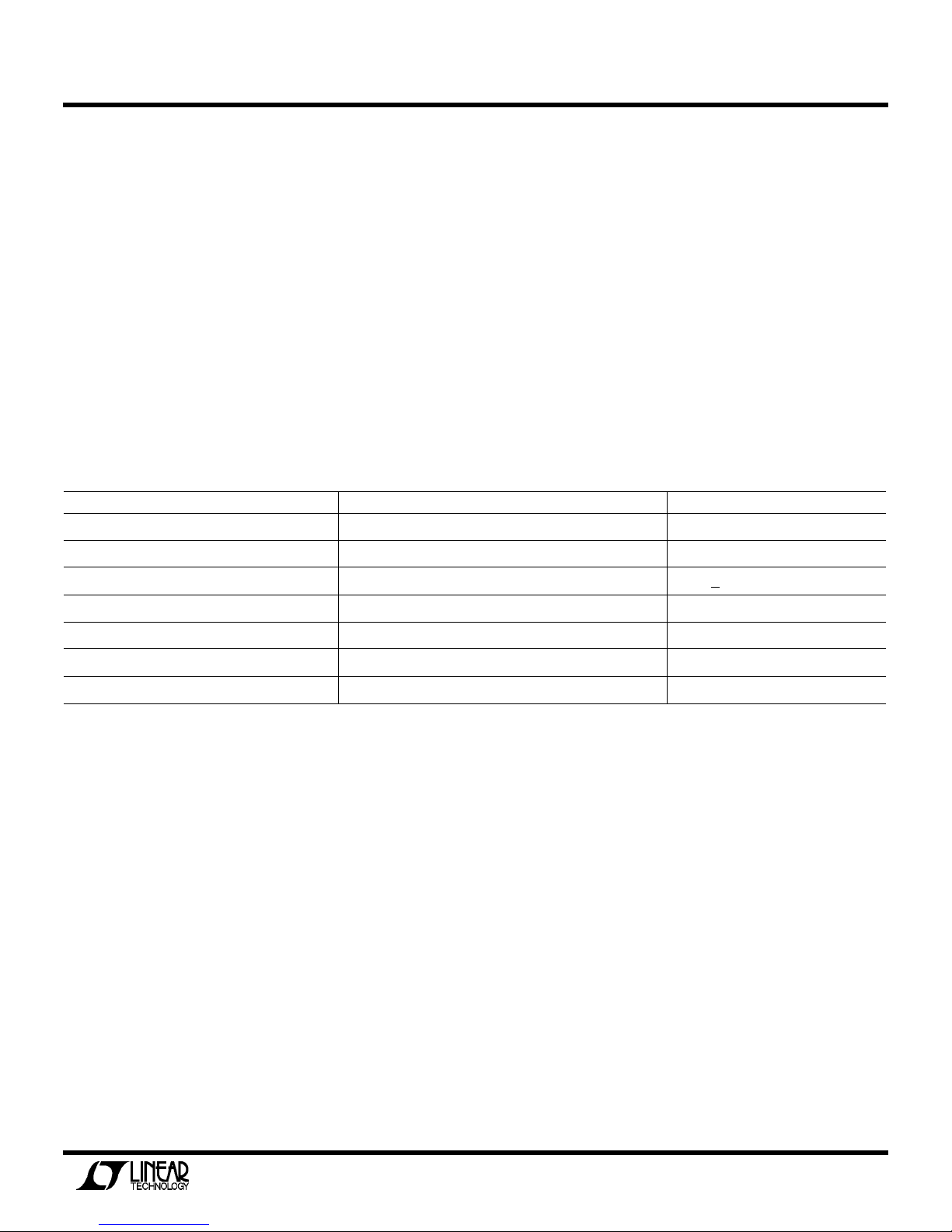
Table 1. PERFORMANCE SUMMARY
PARAMETER CONDITION VALUE
Minimum Input Voltage 4.75V
Maximum Input Voltage 5.5V
V
V
OUT1
V
V
OUT2
Typical V
Nominal Switching Frequency 550kHz
Output Ripple VIN = 5V, I
OUT1
= 4.75V to 5.5V, I
IN
IN_LDO
DS(ON)
= 1.8V, I
CORE
for current limit. This improves efficiency and eliminates cost and
power loss of discrete sense resistors. The LDO can use the switcher
output or an external supply as its
input. The output voltages can be reprogrammed within certain limits in
accordance with LTC1704 specifications.
Design files for this circuit board
are available. Call the LTC factory.
= 0A to 15A 1.8V +2%
OUT1
= 0A to 1.5A 1.5V ±2%
OUT2
= 15A 15mV
P–P
QUICK START PROCEDURE
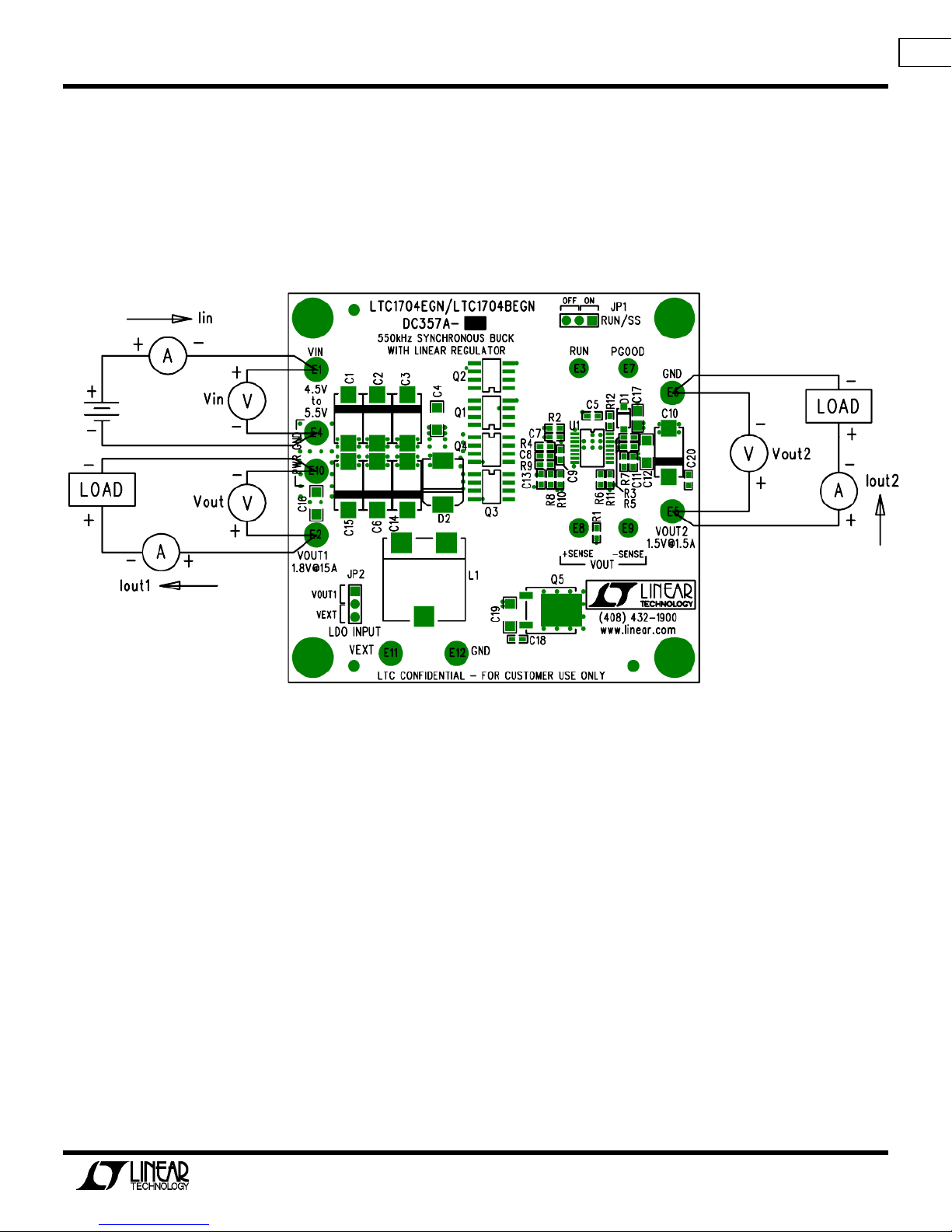
Demonstration circuit 357 is easy to
set up to evaluate the performance of
the LTC1704. Refer to Figure 1 for
1.
Place jumper JP1 in the ON position.
2.
Place Jumper JP2 in VOUT1 position.
proper measurement equipment setup,
3.
and follow the procedure below:
NOTE:
When measuring the input or output voltage ripple, care must be
taken to avoid a long ground lead on
the oscilloscope probe. Measure the
input or output voltage ripple by
touching the probe tip directly
across the Vin or Vout and GND terminals.
With power off, connect the input
power supply to Vin and GND, making
sure voltage is not set greater
than 6V.
4.
Turn on the power at the input. Set
Vin=5V
5.
Check for the proper output voltages. Vout1 = 1.764V to 1.836V,
Vout2 = 1.470V to 1.530V
1
QUICK START GUIDE FOR DEMONSTRATION CIRCUIT 357
550KHZ SYNCHRONOUS BUCK CONVERTER AND LINEAR REGULATOR
If there is no output, temporarily
disconnect the load to make sure
that the load is not set too high.
6.
Once the proper output voltages are
established, adjust the loads
within the operating range and observe the output voltage regulation, ripple voltage, efficiency,
and other parameters.
Figure 1. DC357 Hookup Diagram
2
 Loading...