

Page 1
Flat Washer
M3 Nut
Camera Bracket
Axis (pem stud)
Left
Right
Up
Down
34
12
12
6
Viewing window
for camera
Viewing window
for camera
304.8
152.4
304.8
Pen Stud
for Side-mounted
Camera
Push here to
adust the
camera’s viewing
angle
Camera Bracket
Counter Sinks
HeIgHt strIp camera
Hc serIes
I n s t a l l a t I o n a n d o p e r a t I n g I n s t r u c t I o n s
w w w . l I n e a r c o r p . c o m
Page 2

IMPORTANT SAFEGUARDS
1. Read Instructions - All the safety and operating instructions
should be read before the unit is operated.
2. Retain Instructions - The safety and operating instructions
should be retained for future reference.
3. Heed Warnings - All warnings on the unit and in the
operating instructions should be adhered to.
4. Follow Instructions - All operating and use instructions
should be followed.
5. Cleaning - Unplug the unit from the outlet before cleaning.
Do not use liquid cleaners or aerosol cleaners. Use a damp
cloth for cleaning.
6. Attachments - Do not use attachments not recommended by
the product manufacturer as they may cause hazards.
7. Accessories - Do not place this unit on an unstable stand,
tripod, bracket, or mount. The unit may fall, causing serious
injury to a person and serious damage to the unit. Use only
with a stand, tripod, bracket, or mount recommended by
the manufacturer or sold with the product. Any mounting
of the unit should follow the manufacturer’s instructions
and should use a mounting accessory recommended by the
manufacturer.
An appliance and cart combination should be moved with
care. Quick stops, excessive force, and uneven surfaces
may cause the appliance and cart combination to overturn.
8. Ventilation - Openings in the enclosure, if any, are provided
for ventilation, to ensure reliable operation of the unit, and
to protect it from overheating. These openings must not be
blocked or covered. This unit should not be placed in a builtin installation unless proper ventilation is provided or the
manufacturer’s instructions have been adhered to.
9. Power Sources - This unit should be operated only from
the type of power source indicated on the marking label. If
you are not sure of the type of power supply you plan to
use, consult your dealer or local power company. For units
intended to operate from battery power or other sources,
refer to the operating instructions. This equipment is to be
isolated from the mains supply by a limited power source as
specified in EN60950:1992 Clause 2.11.
10. Grounding or Polarization - This unit may be equipped with
a polarized alternating-current line plug (a plug having one
blade wider than the other). This plug will fit into the power
outlet only one way. This is a safety feature. If you are unable
to insert the plug fully into the outlet, try reversing the plug.
If the plug should still fail to fit, contact your electrician
to replace your obsolete outlet. Do not defeat the safety
purpose of the polarized plug.
Alternately, this unit may be equipped with a 3-wire
grounding-type plug, a plug having a third (grounding) pin.
This plug will only fit into a grounding-type power outlet.
This is a safety feature. If you are unable to insert the plug
into the outlet, contact your electrician to replace your
obsolete outlet. Do not defeat the safety purpose of the
grounding-type plug.
11. Power Cord Protection - Power supply cords should be
routed so that they are not likely to be walked on or
pinched by items placed upon or against them, paying
particular attention to cords and plugs, convenience
receptacles, and the point where they exit from the
appliance.
12. Power Lines - An outdoor system should not be located in
the vicinity of overhead power lines or other electric light
or power circuits or where it can fall into such power lines
or circuits. When installing an outdoor system, extreme care
should be taken to keep from touching such power lines or
circuits as contact with them might be fatal. U.S.A. models only
- refer to the National Electrical Code Article 820 regarding
installation of CATV systems.
13. Overloading - Do not overload outlets and extension cords
as this can result in a risk of fire or electric shock.
14. Object and Liquid Entry - Never push objects of any kind
into this unit through openings, as they may touch dangerous
voltage points or short out parts that could result in a fire or
electric shock. Never spill liquid of any kind on the unit.
15. Servicing - Do not attempt to service this unit yourself as
opening or removing covers may expose you to dangerous
voltage or other hazards. Refer all servicing to qualified
service personnel.
16. Damage Requiring Service - Unplug the unit from the outlet
and refer servicing to qualified service personnel under the
following conditions:
a. When the power supply cord or plug is damaged.
b. If liquid has been spilled or objects have fallen into the
unit.
c. If the unit has been exposed to water and/or inclement
weather (rain, snow, etc.).
d. If the unit does not operate normally by following the
operating instructions. Adjust only those controls that
are covered by the operating instructions, as an improper
adjustment of other controls may result in damage and
will often require extensive work by a qualified technician
to restore the unit to its normal operation.
e. If the unit has been dropped or the cabinet has been
damaged.
f. When the unit exhibits a distinct change in performance--
this indicates a need for service.
17. Replacement Parts - When replacement parts are required,
be sure the service technician has used replacement
parts specified by the manufacturer or have the same
characteristics as the original part. Unauthorized substitutions
may result in fire, electric shock, or other hazards.
18. Safety Check - Upon completion of any service or repairs to
this unit, ask the service technician to perform safety checks
to determine that the unit is in proper operating condition.
19. Coax Grounding - If an outside cable system is connected
to the unit, be sure the cable system is grounded. U.S.A.
models only--Section 810 of the National Electrical Code,
ANSI/NFPA No.70-1981, provides information with respect
to proper grounding of the mount and supporting structure,
grounding of the coax to a discharge unit, size of grounding
conductors, location of discharge unit, connection to
grounding electrodes, and requirements for the grounding
electrode.
20. Lightning - For added protection of this unit during a lightning
storm, or when it is left unattended and unused for long
periods of time, unplug it from the wall outlet and disconnect
the cable system. This will prevent damage to the unit due to
lightning and power line surges.
2
Page 3
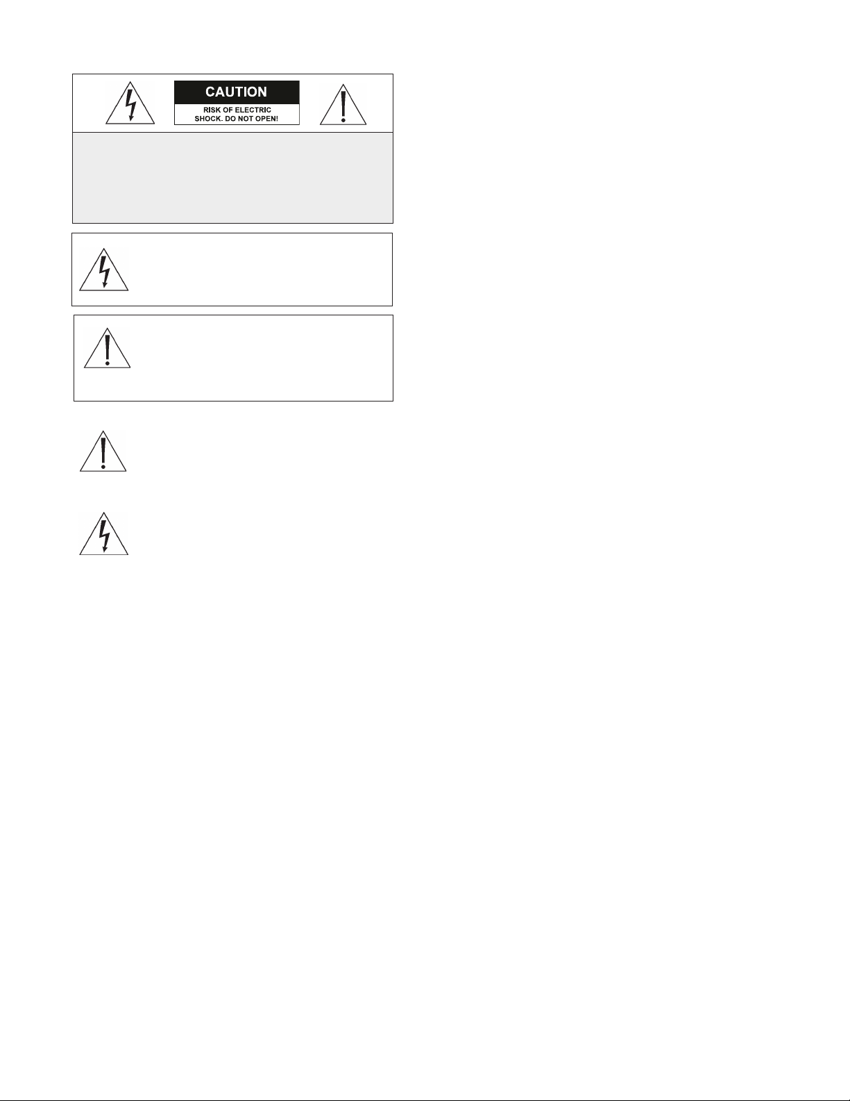
SAFETY PRECAUTIONS
CAUTION: TO REDUCE THE RISK
OF ELECTRIC SHOCK, DO NOT
REMOVE COVER (OR BACK). NO USER
SERVICEABLE PARTS INSIDE. REFER
SERVICING TO QUALIFIED SERVICE
PERSONNEL.
This symbol indicates the presence of
uninsulated “dangerous voltage” within the product’s enclosure. This may
constitute a risk of electric shock.
The user should consult the operating and maintenance (servicing)
instructions in the literature accompanying the appliance.
Attention: Installation should be performed
by qualified service personnel only in accordance with the National Electrical Code or
applicable local codes.
Power Disconnect. Units with or without
ON-OFF switches have power supplied to the
unit whenever the power cord is inserted into
the power source; however, the unit is operational only when the ON-OFF switch is in the ON position. The power cord is the main power disconnect for
all units.
1 UNPACKING
Unpack carefully. This is electromechanical equipment and
should be handled with care.
Check for the following items:
• Verify the unit model number.
• Verify that parts listed below have been included.
HC1CH30-6xx - Height Strip w/ one 650TVL color camera
and 3.0mm lens.
Hardware Kit
5 x Cable Ties
5 x Cable Tie Mounts
3 x Plastic Wall Anchor
3 x No. 8 cross recessed self-tapping screw, 1-1/2” length
1 x Barrel Plug Connector, 2.1mm pin, 36” length,
stripped leads
1 x 12VDC 0.5 Amp Power Adapter, 6-foot cord
CAM-HC1CH30-6 - Accessory 650TVL color camera w/
3.0mm fixed lens
Hardware Kit
1 x 12VDC 0.5 Amp Power Adapter, 6-foot cord
1 x M3 Nylon Lock Nut
1 x Flat Washer
MT-HC – Accessory Wall Bracket to turn the Height Strip
90° Left or Right
3 x M4 Screw, Pan Head Cross Recessed
3 x M4 Lock Nut
Equipment Required
5.5mm or 7/32-inch Nut Driver (or Socket)
7.0mm or 9/32-inch Nut Driver (or Socket)
#2 Cross Recessed Screwdriver
Wire Cutters / Scissors
Level
Drill with 3/8” bit
Optional: Step drill bit or 1/8”, 3/32”, 3/16”, 1/4”, 3/8”
bits
Optional: De-burr tool
Note: Optional items listed above are for use with sidemounted cameras. See Installation section.
If an item appears to have been damaged in shipment,
replace it properly in its carton and notify the shipper.
If any items are missing, notify Aigis Mechtronics Sales
Representative or Customer Service. The shipping carton is
the safest container in which the unit may be transported.
Save it for possible future use. Verify that the parts listed as
follows have been included.
3
Page 4
2 SERVICE
4 DESCRIPTION
If the unit ever needs repair service, the customer should
contact Aigis Mechtronics for return authorization and
shipping instructions.
3 CARE AND MAINTENANCE
Clean the viewing window(s) as needed with a mild, nonabrasive detergent in water and a soft cloth. DO NOT use
alcohol based cleaners to clean the viewing window.
An accessory L-bracket (p/n MT-HC)
can be installed to turn the entire
Height Strip 90° in either direction
to orient the viewing windows parallel
to the wall. This provides a profile
shot of customers entering and
exiting a store.
The camera(s) can be adjusted up to 22°
left or right of center to adjust the view
slightly into or out of the store.
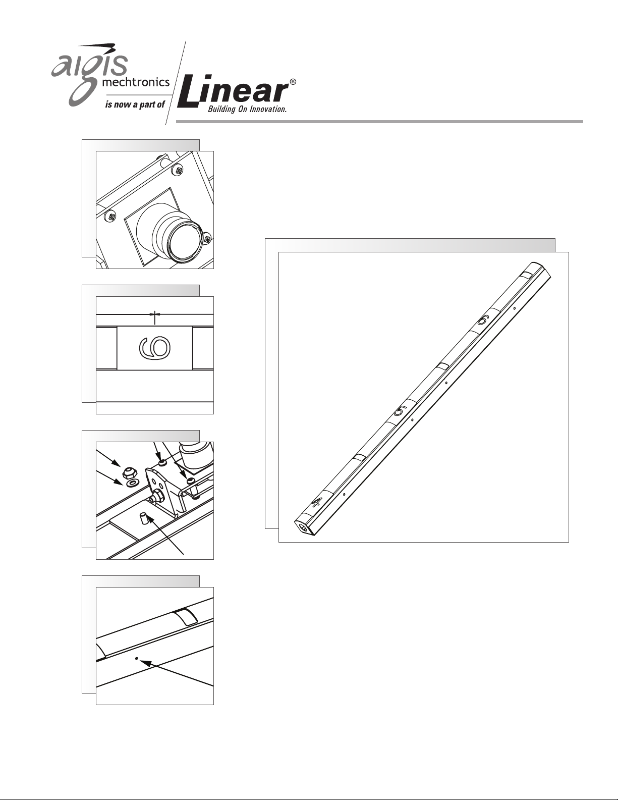
The HC Series of Height Strip camera housings are intended
to improve in-store security in two ways. First, when
installed next to the main entrance of a store, cameras
within the store will capture a subject’s height when exiting
as he or she passes the brightly colored labels. Second, the
Height Strip’s on-board camera will provide a facial shot of
the subject as he or she exits. Each Height Strip unit can
support up to five (5) Color Hi-Resolution cameras. Up to
three (3) cameras can be oriented to look forward through
the curved viewing windows and can be adjusted left or right
of center. Up to an additional two (2) cameras can be turned
90° perpendicular to look directly across the doorway and
provide a profile shot of the subject. Any cameras looking
through the viewing windows can be adjusted 22° left and
right of center. Side-viewing cameras cannot be adjusted,
and require the installer to drill a small hole in the side of the
Height Strip.
Cover
Base
Viewing Window (x3)
Side-Mounted
Cameras
Front-Mounted Cameras
Figure 1 Height Strip Camera
4
Page 5

5 VOlTAGE & MAx WATTAGE
Color Camera 95mA (Max) @ 12VDC
6.2 Camera Removal/Relocation, and
Installing Accessory Camera
Warning: All cameras are powered by DC voltage.
If you are running DC voltage over a pair of wires,
be careful of polarity. A barrel plug connector
with flying leads is provided. The white/black wire
corresponds to the core of the connector, and should be
supplied with +12VDC voltage. The black wire corresponds
to the shell of the connector, and should be used as DC
ground.
6 DISASSEMbly
6.1 Cover Removal
1. Remove the unit from its packaging. Cut open one end of
the plastic tubing covering the Height Strip. Leave the
window masks in place.
2. Using a No. 2 Cross Recessed screwdriver, remove all four
screws that secure the cover (see Figure 2). Remove
cover.
Height Indicator labels not included
with part numbers ending in "N"
1. Each Height Strip ships from the factory with a single
camera installed that looks through the viewing window
located at the 5-1/2 foot mark. Two other viewing
windows are provided at the 4-1/2 foot mark and 6-1/2
foot.
2. To relocate the existing camera, use a 5.5mm (or 7/32”)
nut driver to remove the M3 nut that attaches the
camera bracket to the base (see Figure 4). Remove the
camera and bracket from the base.
3. When installing a new camera or relocating the existing
camera, always refer to the keyhole to ensure the camera
is not installed upside down. The circular part of the
keyhole should face the ground and the slot should face
the ceiling. Always install the camera above the desired
pem stud in the base.
4. Accessory cameras require the own power supply. Do not
double terminate the supplied power adapter.
5. Install all front-facing cameras before proceeding to the
next section.
6. To install a side-mounted camera, refer to the
“Installation – Side-Mounted Cameras” section.
Use a 5.5mm or
7/32” nut driver
to remove or
install cameras.
Front-Mounted
Camera Position
Remove Screws (x4)
Camera
Bracket
Keyhole
Side-mounted
camera position
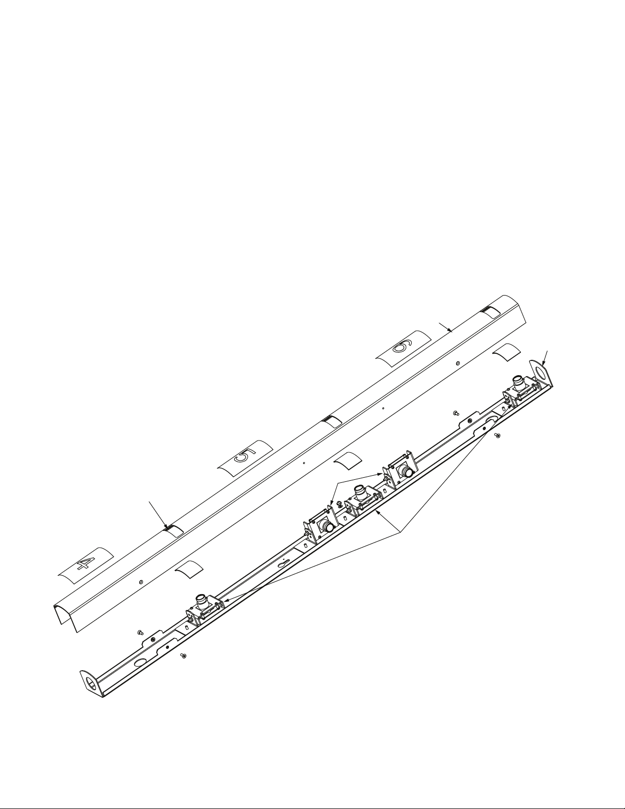
Figure 2 Assembled Height Strip Camera
Cover
Side-mounted
camera position
Front-Mounted
Camera Position
Front-Mounted
Camera Position
Base
Counter Sinks
Pen stud
for side-mounted
camera
Keyhole
M3 Nut
Flat Washer
Push here to
adust the
camera’s viewing
angle
Pen Stud for
Front-mounted
Camera
Camera Bracket
Pen Stud
for Side-mounted
Camera
Figure 3 Internal View Camera Postions
Figure 4 Close up View Camera Position
5
Page 6

7 INSTAllATION
7.1 Side-mounted cameras
Note: If NOT using the side-mounted camera feature of the
Height Strip, proceed to the next applicable section.
1. Refer to Figure 5 when side-mounting a camera.
2. Two positions are available for side-mounted cameras,
one directly below and one directly above the center
mounting location (5.5-foot mark). Select which mounting
location you prefer.
3. Determine which direction the camera should face once
installed. Remember to use the keyhole as a guide. The
round part of the keyhole faces the ground.
4. Change the camera bracket’s pivot point. Remove the
M3 nut, flat washer, and nylon washer from the camera
bracket using a 5.5mm (7/32”) nut driver or socket.
Note: the nylon washer is located between the camera
bracket and the “L” bracket. Be careful not to lose it.
5. Place the nylon washer over the pem stud of the camera
bracket (a.k.a. camera bracket axis), then insert the pem
stud into the side of the “L” bracket OPPOSITE the
direction of the camera. Replace the flat washer and M3
nut and tighten (see “Note” in Figure 5).
6. Before drilling, remove the camera bracket and “L” bracket
from the base. Hold the cover next to the base. Locate
the two small indentations (countersinks) on each side
of the cover. Mark the countersink that corresponds to
your mounting location.
7. Fit the cover back over the base and tighten down the
four (4) M3 screws to secure.
8. Locate the marked countersink in the cover.
9. Drill out an appropriate sized hole in the Height Strip
cover using the following guidelines:
Color Camera
a. If using a step drill bit (recommended), drill the
hole to 3/8-inch diameter.
b. If using standard drill bits, first use a 1/8-inch bit,
then 1/4-inch bit, then a 3/8-inch bit. This will
minimize chatter and help ensure a round hole is
drilled.
10. Remove the four M3 screws to remove the cover.
Remove any burrs from the inside of the cover.
11. Install the camera in the side-mounting location using a
flat washer and M3 nut. Proceed to the next applicable
section to complete the installation.
Flat Washer
M3 Nut
Nylon washer
(in between)
Flat Washer
Original Location
of Axis
M3 Nut
Left
Down
Note:
This camera bracket
has been adjusted
to look 90º RIGHT.
Note that the camera bracket axis
was moved to the LEFT Side of the “L” bracket.
Up
Right
Camera Bracket
Axis (pem stud)
“L” bracket
Figure 5 Side Mounted Cameras
6
Page 7

7.2 Installing the Unit onto a Mullion or
Metal Doorframe
1. Measure from the floor to the 5-foot mark on the mounting surface. Make a mark at 5 feet.
2. Drill a 3/16” hole in the center of the mullion at the
5-foot mark.
3. Remove a #8 self tapping screw and a wall anchor from
the hardware kit.
4. Insert the wall anchor into the hole and tighten the self
tapping screw until only a 1/8” gap remains under the
screw head.
5. Hang the base of the Height Strip onto the screw using
the keyhole. Refer to Figure 6. The two small holes
near the top of the keyhole indicate the 5-foot mark.
Align these holes with the screw and hand-tighten the
screw to hold the base.
6. Use a level to ensure the Height Strip base is held vertically.
7. Use the base as a template to mark the hole location
of the other two mounting holes, as well as mark the
desired through-hole(s) for the power and video cables.
8. Refer to Figure 7 regarding cable entry into the unit.
9. If running cables from the top of the mullion down to the
unit, use the cable through-hole near the 6-foot mark.
If running cables up to the unit from the floor, use the
cable through-hole below the 4-foot mark. Note: If
running cables through the knockouts on the top or
bottom of the unit, disregard this step.
10. Unscrew the base and set aside. Drill out the remaining
two mounting holes (3/16” drill bit) and insert the
remaining wall anchors.
11. At the desired through-hole location(s), drill a hole in the
mullion wide enough to accept the customer-provided
power and video cables.
12. Feed the cables down into the mullion and fish them out
of the through-hole.
13. Hang the Height Strip back on the mounting screw in the
mullion and feed the power and video cables into the
unit.
14. Align the base with the 5-foot mark as in Step 5 of this
section and tighten the screw.
15. Insert the remaining two self tapping screws into the
remaining mounting holes and tighten to secure the base
to the mullion.
16. Terminate the ends of the customer-supplied cables as
required, and connect power and video cables to the
camera(s). Be sure to supply 12VDC with the correct
polarity to the camera. The center pin (black/white
wire) should be connected to +12VDC, and the shell of
the connector (black wire) should be connected to DC
Ground.
17. Use the cable ties and tie wrap mounts provided in the
hardware kit to provide strain relief for the customersupplied cables inside the Height Strip.
18. Orient the camera(s) left or right as desired. Turn the
cameras by pushing on the lower part of the camera
bracket (closest to the camera bracket axis).
19. Check the insides of the viewing windows (see Figure 4)
for any dust or debris. Clean with a Kimwipe™ tissue, if
necessary.
20. Replace the cover and secure with the four M3 flathead
screws.
These holes
indicate the
5-foot mark.
Ceiling
Floor
Figure 6 Keyhole
Note that the top
of the keyhole is NOT
the 5-foot mark.
Extra slot provided
for fine adjustments
during installation.
Knockouts provided at
top and bottom of
Height Strip base
7
Knockouts
Cable-entry through holes
Figure 7 Cable Entry
Page 8

7.3 Installing the Unit onto a Solid Wall
1. Refer to steps 1 to 6 above. Replace fasteners and wall
anchors from the hardware kit with customer-supplied
components as desired. The through-hole size for the
wall mounts is sized for a #8 screw (approximately
0.175” diameter).
2. Use the base as a template to mark the hole location of
the other two mounting holes. Remove the base from
the wall and drill the remaining two mounting holes
(3/16” drill bit).
3. Insert wall anchors into the holes in the wall, then place
the Height Strip base back onto the mounting screw
in the wall. Align the base with the 5-foot mark as in
Step 5 of the previous section. Tighten the remaining
mounting screws to secure the Height Strip base to the
wall.
4. Knockouts are provided at the top and bottom of the unit
for cable entry and conduit fittings.
5. Remove the desired knockout by pushing it into the base
with a screw driver, then bending it back and forth until
it snaps off.
6. Insert an appropriate conduit fitting into the hole, then
run the customer-supplied power and video cables into
the conduit fitting.
7. Refer to Step 14 of the previous section when connecting
video and power cables to the camera.
8. Follow steps 15 – 18 of the previous section to complete
the installation.
7.4 Installing the Unit using the Accessory
Wall Bracket (MT-HC)
Note: cable entry can only be accomplished via the
knockouts at the top or bottom of the Height Strip
when using the MT-HC wall bracket.
1. Refer to Figure 8 and Figure 9 when installing this
accessory.
2. Measure from the floor to the 5-foot mark on the
mounting surface. Make a mark at 5 feet.
3. The side of the MT-HC with the rubber pads and notches,
see Figure 9, near the center through-holes is the side
that gets screwed to the wall. Always use the lower
of the two center through-holes as your 5-foot mark
reference. The Height Strip can be mounted facing
either left or right of the accessory bracket by spinning
the bracket 180°.
4. Orient the bracket as appropriate for your installation.
Line up the notch of the lower through hole with the
5-foot mark.
5. Use the MT-HC bracket as a template to mark the
mounting hole locations.
6. Drill 3/16” holes in the mounting surface if using the
anchors and screws from the Height Strip’s hardware kit.
Drill an appropriate size hole if using other fasteners.
7. Insert wall anchors into the holes and secure the MT-HC
to the mounting location using the screws.
Ensure the M4
screw head is
on THIS side
of the Bracket
once the cover
is secured.
Figure 8 Accessory Wall Bracket (MT-HC)
8
Page 9

Notches designate 5-foot mark.
The mounting holes in the Height Strip
base are not symmetrical.
Ta ke care to select the correct
hole for your particular application.
Figure 9
8. Remove the cover from the Height Strip by removing the
four (4) cross-recessed screws.
9. Orient the Height Strip base as desired. Secure the base
to the MT-HC accessory bracket using three (3) M4
screws and three (3) M4 nuts from the hardware kit
sent with the MT-HC.
10. Ensure that the heads of the screws will be outside the
unit and the nuts will be inside the unit once the cover
is replaced.
11. Tighten the screws using a cross recessed screwdriver
and a 7mm (9/32”) socket or nut driver.
12. Knockouts are provided at the top and bottom of the
unit for cable entry and conduit fittings.
13. Remove the desired knockout by pushing it into the base
with a screw driver, then bending it back and forth until
it snaps off.
14. Insert an appropriate conduit fitting into the hole, then
run the customer-supplied power and video cables into
the conduit fitting.
15. Terminate the ends of the customer-supplied cables as
required, and connect power and video cables to the
camera(s). Be sure to supply 12VDC with the correct
polarity to the camera. The center pin (black/white
wire) should be connected to +12VDC, and the shell of
the connector (black wire) should be connected to DC
Ground.
16. Use the cable ties and tie wrap mounts provided in the
hardware kit to provide strain relief for the customersupplied cables inside the Height Strip.
17. Orient the camera(s) left or right as desired. Turn the
cameras by pushing on the lower part of the camera
bracket (closest to the camera bracket axis).
18. Check the insides of the viewing windows for any dust or
debris. Clean with a Kimwipe™ tissue, if necessary.
19. Replace the cover and secure with the four M3 flathead
screws to complete the installation.
9
Page 10

DIMENSIONAl OUTlINES
Back View
Back View
Side View
To p Down
1.7
43.2
1.6
40.6
Viewing window
for camera
in
mm
7.5
190.5
(ø.19 X3) MOUNTING HOLES
14.7
374.7 247.7
12
304.8
Viewing window
for camera
34
863.6
6
152.4
9.7
12
304.8
Viewing window
for camera
Bottom Up
2.5
63.5
3
76.2
10
Page 11

11
Page 12

Now Part of
www.aigismech.com • www.linearcorp.com
1950 Camino Vida Roble, Suite 150
Carlsbad, CA 92008
Tel: 760.438.7000 800.421.1587
100 0266 002 AIG 02/12
Data subject to change without notice.
Copyright © 2012 Linear LLC
 Loading...