

Linear H560 Owner's Manual
H560
MUSIC & COMMUNICATIONS
DISTRIBUTION CENTER
Page 2 ©2004 Linear LLC. All Rights Reserved. 07/04
INSTALLATION MANUAL
H560
IMPORTANT SAFETY INFORMATION
Read Information—All the safety and operating information should be read before the appliance is operated.
Follow Information—All operating and use information should be followed.
Retain Information—The safety and operating information should be retained for future reference.
Heed Warnings—All warnings on the appliance and in the operating instructions should be heeded.
Wall Mounting—Mounting of this appliance should be done only by an authorized installer.
Ventilation—The appliances should be situated so that their location or position does not interfere with their proper ventilation.
These appliances should never be placed near or over a radiator or heat register. These appliances should not be placed in a built-in
installation such as a bookcase or cabinet that may impede the flow of air through the ventilation openings.
Non-Use Periods—Appliances that are left unattended and unused for long periods of time should be de-energized.
Power Sources—The appliances should be connected to a power supply only of the type described in the operating instruc-
tions or as marked on each appliance. If you are not sure of the type of power supply to your home, consult your authorized ELAN dealer or local power company.
Grounding or Polarization—These audio products must be connected to a grounding-type alternating-current circuit on
a dedicated circuit breaker. This is a safety feature. The green safety wire from the A.C. circuit must be connected.
WARNING
RISK OF ELECTRIC SHOCK
DO NOT OPEN!
CAUTION: TO REDUCE THE RISK OF ELECTRIC SHOCK, DO NOT
REMOVE COVER (OR BACK). NO USER SERVICEABLE PARTS INSIDE.
REFER SERVICING TO QUALIFIED SERVICE PERSONNEL.
The lightning flash with arrowhead symbol within an equilateral triangle
is intended to alert the user to the presence of uninsulated "dangerous
voltage" within the product's enclosure that may be of sufficient
magnitude to constitute a risk of electric shock to persons.
The exclamation point within an equilateral triangle is intended to alert
the user to the presence of important operating and maintenance
(servicing) instruction in the literature accompanying the appliance.
WARNING: TO REDUCE THE RISK OF FIRE OR SHOCK,
DO NOT EXPOSE THIS APPLIANCE TO RAIN OR MOISTURE.
©2004 Linear LLC. All Rights Reserved. 07/04. Page 3
INSTALLATION MANUAL
H560
Water and Moisture—To reduce the risk of electric shock or fire, these appliances should not be used near water––for
example, near a bathtub, washbowl, kitchen sink, laundry tub, in a wet basement, or near a swimming pool.
Power Cord Protection—A.C.Power supply circuits should be routed by a certified electrician only, in accordance with
the NEC standards.
Telephones—Avoid using a telephone (other than a cordless type) during an electrical storm. There may be a remote risk of
electrical shock from lightning. Do not use a telephone to report a gas leak if the leak is in the vicinity of the OpenHouse electronic
equipment because of risk of fire or explosion.
Cleaning—Turn off the circuit breaker to this audio product before cleaning. Do not use liquid or aerosol cleaners. Use a damp
cloth for cleaning.
Power Lines—An outdoor antenna should be located away from power lines. When installing an outside antenna system,
extreme care should be taken to avoid touching power lines or circuits, as contact with them may be fatal.
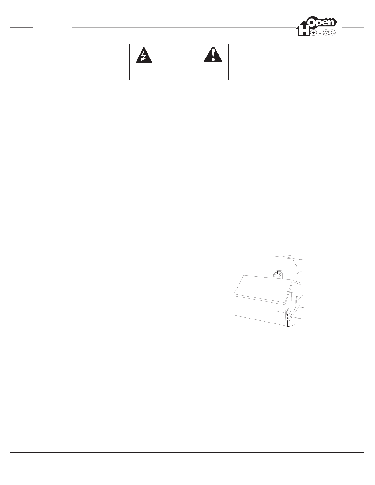
Outdoor Antenna Grounding—If an outside antenna or cable system is connected to these audio products, be sure
the antenna or cable system is grounded so as to provide some protection against voltage surges and built-up static charges. Section
810 of the U.S. National Electrical Code, and Section 54 of the Canadian Electrical Code, provide information with respect to proper
grounding of the mast and supporting structure, grounding of the lead-in wire to an antenna discharge unit, size of grounding conductors, location of antenna-discharge unit, connection to grounding electrodes, and requirements for the grounding electrode. See the
grounding diagram (right).
Overloading—Do not overload wall outlets and extension cords, as this could result in fire or electric shock.
Object and Liquid Entry—Never insert objects of any kind
through the openings of these appliances, as they may touch dangerous voltage points or short-out parts that could result in a fire or electric shock. Care
should be taken so that objects do not fall and liquids are not spilled into the
appliance through openings in the enclosure.
Servicing—Do not attempt to service these appliances yourself, as open-
ing or removing covers may expose you to dangerous voltage or other hazards. Refer all servicing to qualified service personnel.
Damage Requiring Service—These appliances should be ser-
viced by qualified service personnel when:
• A power supply connection or a plug has been damaged or
• If liquid has been spilled into the appliance or objects have fallen into
the appliance or
• The appliance has been exposed to water or moisture or
• The appliance does not appear to operate normally or exhibits a marked change in performance or
• The appliance has been dropped or the enclosure damaged.
Replacement Parts—When replacement parts are required, be sure the service technician has used replacement parts
specified by the manufacturer or that have the same characteristics as the original part. Unauthorized substitutions may result in fire,
electric shock, or other hazards. The Master Control Unit battery should be replaced only after turning the power off and only by an
authorized installer.
Safety Check—Upon completion of any service or repairs to this audio product, ask the service technician to perform safety
checks to determine that the audio product is in proper operating condition.
Lightning—For added protection for these audio products during an electrical storm, or when they are left unattended and
unused for long periods of time, turn off the circuit breaker, and disconnect the antenna or cable system. This will prevent damage to
the audio products due to lightning and power-line surges.
WARNING
RISK OF ELECTRIC SHOCK
DO NOT OPEN
Grounding
Diagram
ELECTRIC
SERVICE
EQUIPMENT
NEC - NATIONAL ELECTRICAL CODE
CEC - CANADIAN ELECTRICAL CODE
GROUND
CLAMPS
ANTENNA
LEAD-IN WIRE
ANTENNA LEAD-IN WIRE
(CEC SECTION 54-200)
(NEC SECTION 810-20)
GROUNDING CONDUCTORS
(CEC SECTION 54-200)
(NEC SECTION 810-21)
GROUND CLAMPS
POWER SERVICE GROUNDING
ELECTRODE SYSTEM
(CEC SECTION 10-700)
(NEC ARTICLE 250, PARTH)

Page 4 ©2004 Linear LLC. All Rights Reserved. 07/04
INSTALLATION MANUAL
H560
IMPORTANT USER INFORMATION
H560 has been registered with the Federal Communications Commission (FCC) in accordance with Parts 68 of its rules. On
the front panel of the H560 Music & Communications Distribution Amplifier is a label that contains, among other information,
the FCC registration number and ringer equivalence number (REN) for this equipment. If requested, this number must be
given to the telephone company.
FCC Registration Number: 5J7USA-30852-MA-T
Ringer Equivalence Number (REN): 0.6B 1.1F
Load Number (LN): 12B (Canada only)
The REN is useful in determining the quantity of devices you may connect to your telephone line and still have all those
devices ring when your number is called. In most, but not all areas, the sum of all RENs of all devices connected to one line
should not exceed five (5.0). To find out the number of devices you may connect to your line, as determined by the REN,
contact your local telephone company for the maximum REN for your calling area.
If your telephone equipment causes harm to the telephone network, the telephone company may discontinue your service
temporarily. If possible, they will notify you in advance. But, if advance notice isn’t practical, you will be notified as soon as
possible. You will be notified of your right to file a complaint with the FCC.
Your telephone company may make changes in its facilities, equipment, operations, or procedures that could affect the
proper functioning of your equipment. If they do, you will be notified in advance to give you an opportunity to maintain uninterrupted telephone service. If you experience trouble with this telephone equipment, please contact TECHNICAL SUPPORT
at 1-800-999-5225 for information on obtaining service or repairs. The telephone company may ask that you disconnect this
equipment from the network until the problem has been corrected or until you are sure the equipment is not malfunctioning.
If the telephone features are not functioning or are malfunctioning, switch off the circuit breaker connected to the system.
This will directly connect the telephone line with all the telephones connected to the package. Contact your dealer for
repairs.
This equipment may not be used on coin service provided by the telephone company. Connection of party lines is
subject to state tariffs. (Contact your state public utility commission for information).
This device complies with Part 15 of the FCC Rules. Operation is subject to the following conditions: (1) This device
may not cause harmful interference and (2) this device must accept any interference received, including interference
that may cause undesired operation.
Notice
The Industry Canada label identifies certified equipment. This certification means that the equipment meets certain telecommunications network protective, operational, and safety requirements. Industry Canada does not guarantee the equipment
will operate to the user’s satisfaction.
Before installing this equipment, users should ensure that it is permissible to be connected to the facilities of the local
telecommunications company. The equipment must also be installed using an acceptable method of connection. In some
cases, the company’s inside wiring associated with a single line individual service may be extended by means of a certified
connector assembly (telephone extension cord). The customer should be aware that compliance with the above conditions
may not prevent degradation of service in some situations.
The Load Number (LN) determines the number of devices you may connect to your line. The LN sum of all devices connected to one line shall not exceed 100.
Repairs to certified equipment can only be made by your local OpenHouse Installer.
This digital apparatus does not exceed the Class B limits for radio noise emissions from digital apparatus set out in the
Radio Interference Regulations of Industry Canada.
Contact TECHNICAL SUPPORT at 1-800-999-5225 for repairs to certified equipment.

©2004 Linear LLC. All Rights Reserved. 07/04. Page 5
INSTALLATION MANUAL
H560
Table of Contents
Safety Information............................................................... 2
System Overview..................................................................6
1. Distribution Center Installation.................................... 7
2. Audio Connections.......................................................... 9
3. Control Device Connections......................................... 14
4. Telephone and Door Station Connections...................20
5. Troubleshooting............................................................... 26
Warranty................................................................................ 35
Telephone Quick Reference..................................Back Page

Page 6 ©2004 Linear LLC. All Rights Reserved. 07/04
INSTALLATION MANUAL
H560
y)
PA
TENTS:
5,130,893
5,327,144
5,131,048
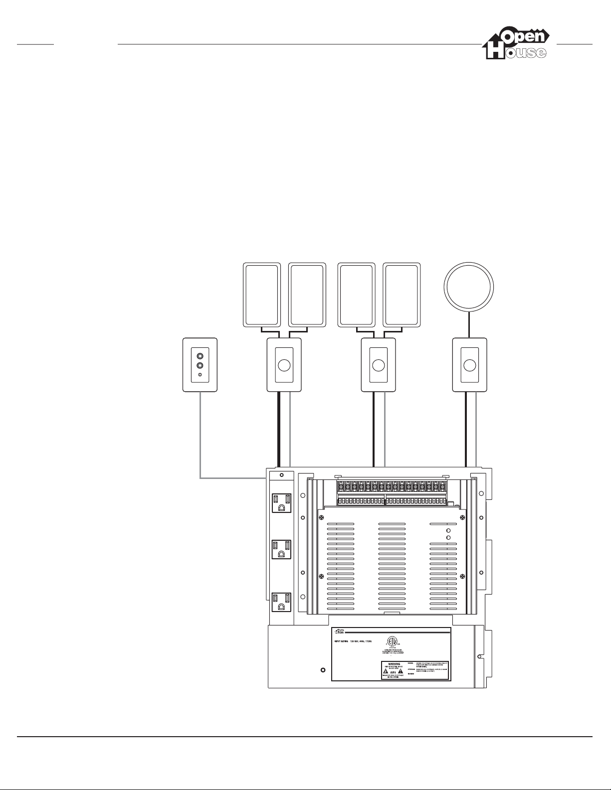
H560 System Overview & Wire Runs
In-Wall or In-Ceiling Speakers
H561
Music Input
Wall Plate
Door Station
(H580/H581)
OR
Door Station w/
Color CCTV Camera
(H585)
Dedicated electrical circuit
(to be connected by a
licensed electrician onl
CAT5
4 Conductor
Speaker Wire
4 TwistedPair Shielded
Wire w/ Drain
4 TwistedPair Shielded
Wire w/ Drain
Coax
To Video
Distribution
Module
Romex
H572
Stereo Volume
Controls w/
Override
CAT5
(Optional)
4 Conductor
Speaker Wire
®
LinearLLC
Carlsbad,CA 92009,USA
www.openhousesystems.com
©2004 LinearCorporation, Carlsbad,CA, USA
H571
Mono Volume
Control w/
Override
CAT5
(Optional)
CAT5
(Optional)
CAT5
2 Conductor
Speaker Wire
Multi-RoomAudio& IntercomSystem
modelH560
NOTICES:
THISDEVICECOMPLIES WITHFCCPART15RULESAND
SUBJECTTOTHE
REGULATIONS. OPERATIONIS
FOLLOWINGTWO CONDITIONS:(1)THISDEVICEMAY
NOTCAUSE HARMFULINTERFERENCEAND(2)THIS
DEVICE ACCEPTANYINTERFERENCE THAT
MUST
MAYCAUSE UNDESIREDOPERATION.
THISDIGITAL ISCERTIFIEDTO COMPLYWITH
APPARATUS
THELIMITSOF ACLASS BDIGITALDEVICE PURSUANT
TO
OFFCCRULES. SEE INSTRUCTIONMANUALIF
PART15
INTERFERENCETORADIO RECEPTIONIS SUSPECTED.
COMPLIESWITHFCC PART68
MADEIN CHINAP/N:930019592REVA
FCCREGISTRATIONNUMBER: 5J7USA-30852-MA-T
RINGEREQUIVALENCE:0.6B
5,130,893
TENTS:
PA
NOUSERSERVICEABLE PARTSINSIDE.
REFERSERVICETO OPENHOUSE
APPROVEDSERVICETECHNICIAN.
5,327,144
5,131,048
CAT5 MUST BE RUN TO VOLUME
CONTROLS IF UTILIZING PAGE
AND/OR DOORBELL FEATURES!
2131
In-Wall
IR Target
©2004 Linear LLC. All Rights Reserved. 07/04. Page 7
INSTALLATION MANUAL
H560
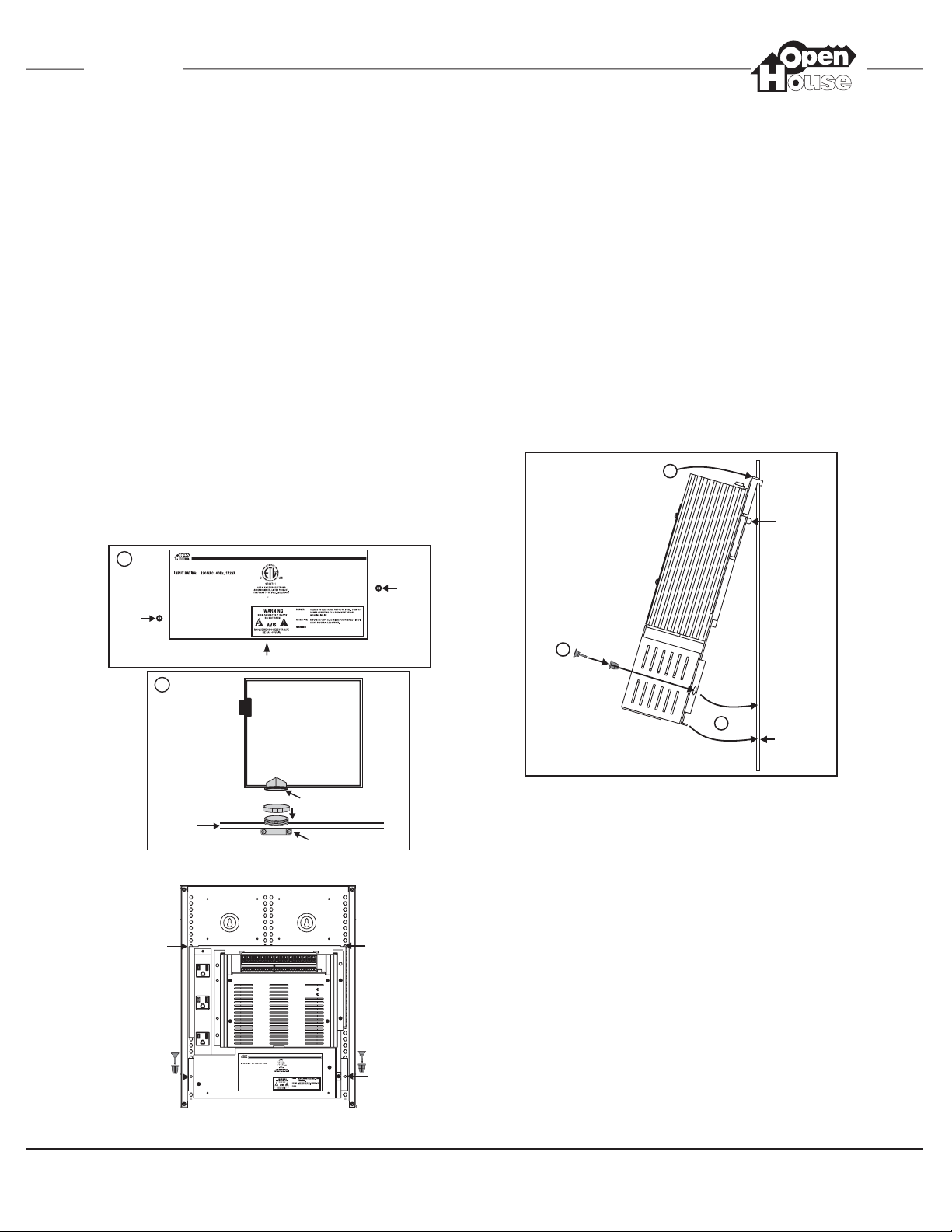
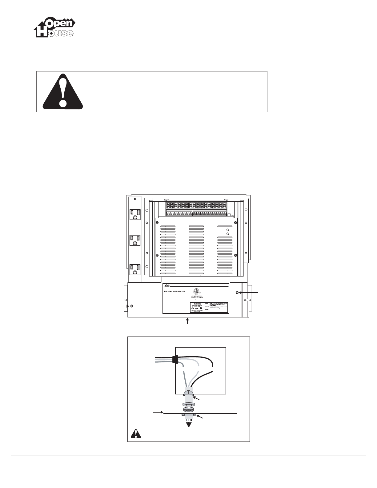
1. Distribution Center Installation
To mount the H560 into an Enclosure :
1. Remove power supply cover. Be sure not to lose
the screws once you remove them!
2. Install cable connectors into hole at bottom of the
H560 power supply compartment and into 3/4”
knock-out at bottom of the enclosure. It is
important that this be done now as access will
not be available once the H560 pan has been
attached to the grid. Replace power supply compartment cover when done.
3. Push ‘Snap Latch’ grommets (2) into the holes of
the H560 pan. Push ‘Snap Latch’ pins half-way
into grommets.
4. Hook pan to the grid from the top. See diagrams
below for installing the H560 into enclosures.
Different grill holes are used for each enclosure.
5. Slowly swing pan into place. Metal nub and bottom hook fit into grid holes, providing additional
support.
6. Push Snap Latch pins fully into grommets to lock
the H560 in place.
PA
TENTS:
5,130,893
5,327,144
5,131,048
PA
TENTS:
5,130,893
5,327,144
5,131,048
1
Screw
Linear LLC
Carlsbad,CA 92009,USA
www.openhousesystems.com
©2004 LinearCorporation, Carlsbad, CA,USA
2
®
MADE INCHINAP/N:930019592REVA
Power Supply Compartment
Multi-RoomAudio &Intercom System
NOTICES:
THISDEVICE COMPLIESWITHFCC PART15 RULESAND
REGULATIONS. OPERATIONIS
FOLLOWINGTWO CONDITIONS:(1) THISDEVICE MAY
NOTCAUSE HARMFULINTERFERENCE AND(2) THIS
MUST
DEVICE ACCEPT ANYINTERFERENCE THAT
MAYCAUSE UNDESIRED OPERATION.
APPARATUS
THISDIGITAL ISCERTIFIEDTO COMPLYWITH
THELIMITS OFA CLASSB DIGITALDEVICEPURSUANT
PART15
OFFCC RULES.SEE INSTRUCTIONMANUAL IF
INTERFERENCETORADIO RECEPTION ISSUSPECTED.
COMPLIESWITH FCCPART68
FCCREGISTRATIONNUMBER: 5J7USA-30852-MA-T
RINGEREQUIVALENCE:0.6B
PA
TENTS:
5,327,144
5,130,893
NOUSER SERVICEABLEPARTSINSIDE.
REFERSERVICE TOOPENHOUSE
APPROVEDSERVICE TECHNICIAN.
modelH560
SUBJECTTOTHE
TO
5,131,048
Screw
H560 Power
Supply
Compartment
4
Nub fits into
grid hole for
additional
support
3
NOTE:
A second Snap Latch
needs to be inserted
on the other side of
the H560 as well
5
Hook fits into
grid hole for
additional
support
Use 3/4" Knockout
at bottom of
H318/H336 Enclosure
Plastic Cable Connector
Metal Cable Connector
H318 or H336 Enclosure
25th grid
hole from
the bottom
4th grid
hole from
the bottom
®
LinearLLC
Carlsbad,CA92009,USA
www.openhousesystems.com
©2004LinearCorporation, Carlsbad,CA,USA
MADEINCHINAP/N:930019592REVA
NOTICES:
THISDEVICECOMPLIESWITHFCC PART15RULESAND
REGULATIONS.OPERATIONIS
FOLLOWINGTWOCONDITIONS:(1) THISDEVICEMAY
NOTCAUSEHARMFULINTERFERENCEAND (2)THIS
DEVICE ACCEPTANYINTERFERENCETHAT
MAYCAUSEUNDESIREDOPERATION.
THISDIGITAL ISCERTIFIEDTOCOMPLYWITH
THELIMITSOFACLASS BDIGITALDEVICEPURSUANT
PART15
INTERFERENCETORADIORECEPTION ISSUSPECTED.
COMPLIESWITHFCCPART68
FCCREGISTRATIONNUMBER:5J7USA-30852-MA-T
RINGEREQUIVALENCE:0.6B
TENTS:
PA
5,130,893
Multi-RoomAudio&IntercomSystem
MUST
NOUSERSERVICEABLEPARTSINSIDE.
REFERSERVICETOOPENHOUSE
APPROVEDSERVICETECHNICIAN.
APPARATUS
OFFCCRULES.SEE INSTRUCTIONMANUALIF
5,327,144
5,131,048
modelH560
SUBJECTTOTHE
TO
25th grid
hole from
the bottom
4th grid
hole from
the bottom
Page 8 ©2004 Linear LLC. All Rights Reserved. 07/04
INSTALLATION MANUAL
H560
1. Remove power supply cover (be sure not to lose
the screws once you remove them!)
A cable connector should already have been
installed in the hole at bottom of the H560
power supply compartment and in the 3/4”
knock-out at bottom of enclosure . If not, you will
need to remove the H560 from the grid and follow
the directions on p. 7.
2. Connect the H560 to a dedicated electrical circuit as shown in the diagram below.
3. Replace power supply compartment cover when
finished.
120VAC Connections
PA
TENTS:
5,130,893
5,327,144
5,131,048
WARNING:
All 120VAC Electrical Connections Should
be Made by a Licensed Electrician Only!
®
Remove
Screw
LinearLLC
Carlsbad,CA 92009,USA
www.openhousesystems.com
©2004 LinearCorporation, Carlsbad,CA, USA
Multi-RoomAudio& IntercomSystem
modelH560
NOTICES:
THISDEVICECOMPLIES WITHFCC PART15RULESAND
REGULATIONS. OPERATIONIS
SUBJECTTOTHE
FOLLOWINGTWO CONDITIONS:(1)THIS DEVICEMAY
NOTCAUSE HARMFULINTERFERENCEAND (2)THIS
DEVICE ACCEPTANYINTERFERENCE THAT
MUST
MADEIN CHINAP/N:930019592REVA
MAYCAUSE UNDESIREDOPERATION.
THISDIGITAL ISCERTIFIEDTO COMPLYWITH
APPARATUS
THELIMITSOF ACLASS BDIGITALDEVICE PURSUANT
OFFCCRULES. SEE INSTRUCTIONMANUALIF
PART15
INTERFERENCETORADIO RECEPTIONIS SUSPECTED.
COMPLIESWITHFCC PART68
FCCREGISTRATIONNUMBER: 5J7USA-30852-MA-T
RINGEREQUIVALENCE:0.6B
5,130,893
TENTS:
5,327,144
PA
NOUSERSERVICEABLE PARTSINSIDE.
REFERSERVICETO OPENHOUSE
APPROVEDSERVICETECHNICIAN.
TO
5,131,048
Remove
Screw
Power Supply Compartment
H560 Power Supply Compartment
From
Transformer
Green
Use 3/4" Knockout
at Bottom of
BlackWhite
Plastic Cable Connector
H318/H336
Enclosure
Metal Cable Connector
Romex to Dedicated Electrical Circuit
(To be connected by a licensed electrician only)
©2004 Linear LLC. All Rights Reserved. 07/04. Page 9
INSTALLATION MANUAL
H560
PA
TENTS:
5,130,893
5,327,144
5,131,048
2. Audio Connections
This section details the audio connections necessary for proper installation of the H560.
These connections include:
Music Input Wall Plate (H561)
Volume Controls (H571/H572)
Speakers (Mono and/or Stereo)
In-Wall or In-Ceiling Speakers
H561
Music Input
Wall Plate
CAT5
(100' Max)
4 Conductor
Speaker Wire
NOTE:
For wire runs less than
80 feet, use 16 or 18 GA
Twisted Pair for each
channel.
For wire runs longer than
80 feet, use 14 GA Twisted
Pair for each channel.
H572
Stereo Volume
Controls w/
Override
CAT5
(Optional)
4 Conductor
Speaker Wire
®
Linear LLC
Carlsbad,CA 92009,USA
www.openhousesystems.com
©2004 LinearCorporation, Carlsbad,CA, USA
CAT5
(Optional)
MADE INCHINAP/N:930019592REVA
2 Conductor
Speaker Wire
Multi-RoomAudio &Intercom System
THISDEVICECOMPLIES WITHFCC PART15RULES AND
REGULATIONS. OPERATIONIS
FOLLOWINGTWO CONDITIONS:(1) THISDEVICE MAY
NOTCAUSE HARMFULINTERFERENCE AND(2)THIS
DEVICE ACCEPTANY INTERFERENCETHAT
MUST
MAYCAUSE UNDESIRED OPERATION.
THISDIGITAL ISCERTIFIEDTOCOMPLYWITH
APPARATUS
THELIMITSOF A CLASSBDIGITAL DEVICEPURSUANT
OFFCCRULES. SEE INSTRUCTIONMANUAL IF
PART15
INTERFERENCETORADIO RECEPTION ISSUSPECTED.
COMPLIESWITHFCC PART68
FCCREGISTRATIONNUMBER: 5J7USA-30852-MA-T
RINGEREQUIVALENCE:0.6B
TENTS:
5,327,144
5,130,893
NOUSER SERVICEABLEPARTSINSIDE.
REFERSERVICETO OPENHOUSE
APPROVEDSERVICETECHNICIAN.
modelH560
SUBJECTTOTHE
5,131,048
NOTICES:
PA
H571
Mono Volume
Control w/
Override
CAT5
(Optional)
TO
Page 10 ©2004 Linear LLC. All Rights Reserved. 07/04
INSTALLATION MANUAL
H560
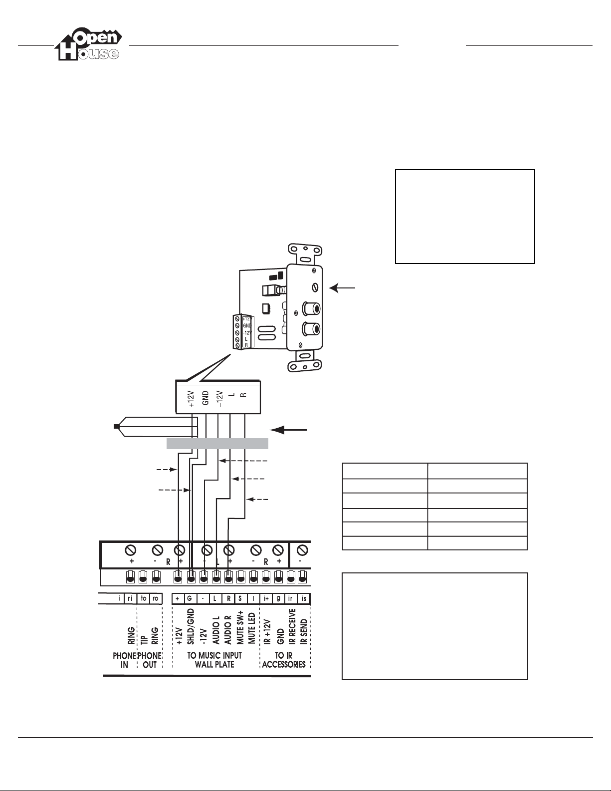
Connecting the Music Input Wall Plate to the H560
The H561 Music Input Wall Plate is an
in-wall preamp that sends the audio
from the homeowner’s receiver to the
H560.
This is a LINE LEVEL input only (Tape
Out).
DO NOT Connect Speaker Level
Audio to the H560 as this will
damage the unit!
OpenHouse recommends the use
of a FIXED line level output (Tape
Out, for example) from the receiver so that music can be heard in
every room regardless of the
receiver’s volume setting.
H561
Music Input
Wall Plate
INPUT Level
Adjustment
Brown/Wh
Green/Wh
Orange/Wh
Blue
Blue/Wh
Orange
Green
Brown
CAT5 Cable
H560 H561 Wall Plate
+12 V Blue +12V
SHLD/GND Blue/Wh GND
-12 V Orange -12V
AUDIO L Green L
AUDIO R Brown R
Ground Return Connections
Connect the Brown/Wh, Orange/Wh,
& Green/Wh to the SHLD/GND
terminal of the H560. The other
end of these conductors should
be twisted together and left
disconnected at the H561 Wall
Plate as shown.
©2004 Linear LLC. All Rights Reserved. 07/04. Page 11
INSTALLATION MANUAL
H560
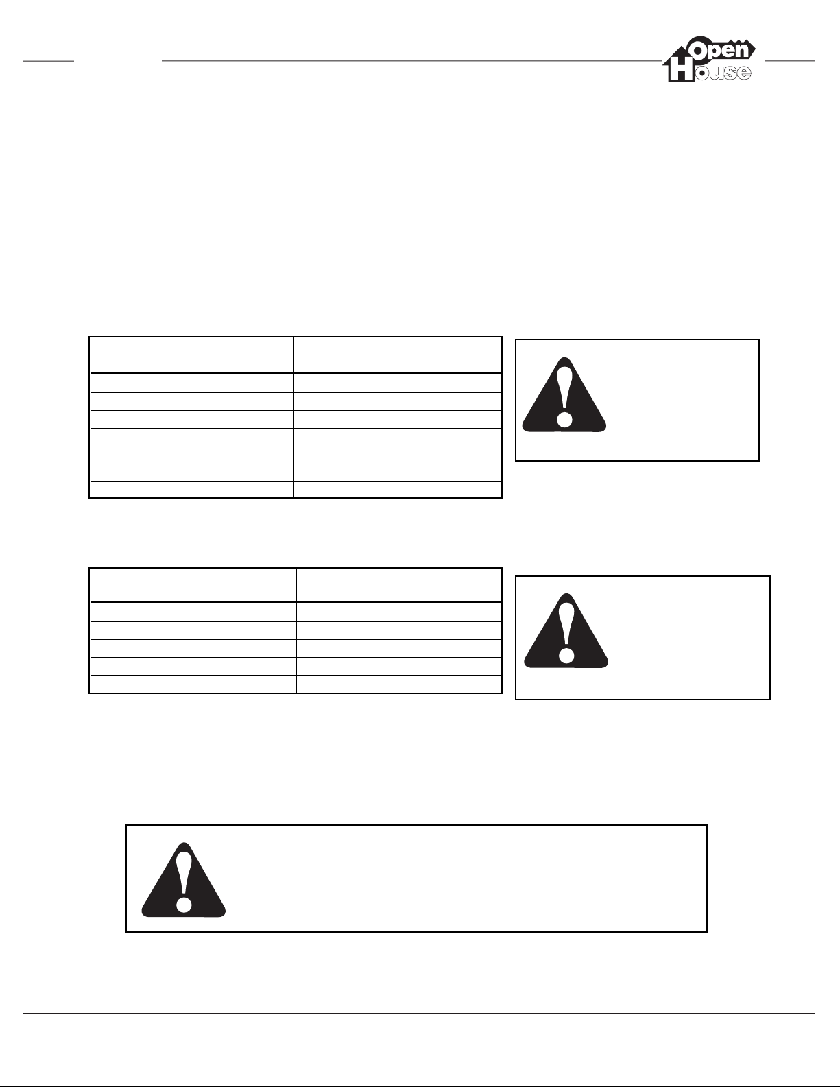
Determining the Maximum Amount of Speakers and Volume Controls
w/ Override That Can Be Connected to the H560.
The following tables assume:
1. One H572 Stereo Volume Control w/ Override at an impedance match setting of 8X per 8
ohm stereo pair.
2. One H571 Mono Volume Control w/ Override at an impedance match setting of 16X per 8 ohm
mono speaker.
3. All mono speakers are distributed evenly between the H560’s mono speaker connections.
Number of 8 Ohm Stereo Speaker Maximum Number of 8 Ohm
Pairs Connected to the H560 Mono Speakers Allowed
024
120
216
312
48
54
60
Number 4 or 6 Ohm Stereo Speaker Maximum Number of 8 Ohm
Pairs Connected to the H560 MONO Speakers Allowed
012
19
26
33
40
Failure to comply with the
Maximum Speaker and
Override Volume Control
Specifications may cause
damage to the amplifier
and will VOID the manufacturer’s warranty.
Based on the same assumptions, the table below indicates the combinations of Stereo and
Mono speakers that can be connected to the H560 when using 4 or 6 Ohm speakers.
A maximum of 12 Volume Controls using the Override Feature
can be connected to the H560. See page 15 for further details.
The H560 is designed specifically for use with OpenHouse H571
and/or H572 Volume Controls w/ Override ONLY! Failure
to comply with this specification may cause damage to the
amplifier and will VOID the manufacturer’s warranty.
All H572 Stereo Volume
Controls must be set to
8X Impedance Match.
All H571 Mono Volume
Controls must be set to
16X Impedance Match.
 Loading...