

Page 1

DESCRIPTION
The Models D-8C and D-8CW are eight-channel, 12 Volt
digital UHF receivers useful in wireless security systems and
remote control applications. Typically, the receiver is
connected to the inputs of a hardwire alarm control panel,
giving the control panel wireless capability.
Each of the receiver’s eight channels controls a solid state
output. The circuits associated with these outputs are
normally open until activated. When activated, the outputs
switch to ground and trigger the control panel zone (see
Figure 1).
A 15-inch ribbon cable exits the receiver for power and
output connections. The D-8CW has a 10-position connector
on the cable for easy installation to compatible control
panels. See Figure 2 for D-8C connections and Figure 3 for
D-8CW connections.
E-O-L RESISTORS WIRED
TO LOOP COMMON FOR
ANY ZONES THAT NEED THEM
CHANNEL 1 - BROWN
CHANNEL 2 - RED
CHANNEL 3 - ORANGE
CHANNEL 4 - YELLOW
CHANNEL 5 - GREEN
CHANNEL 6 - BLUE
D-8C
RECEIVER
CHANNEL 7 - PURPLE
CHANNEL 8 - GRAY
COMMON (-) WHITE
POWER (+) BLACK
Figure 1. Normally Open Outputs Connected to Control
Panel
TYPICAL CONTROL
PANEL TERMINALS
ZONE 1
NEGATIVE
ZONE 2
ZONE 3
NEGATIVE
ZONE 4
ZONE 5
NEGATIVE
ZONE 6
ZONE 7
NEGATIVE
ZONE 8
NEGATIVE
+12 VDC AUX
Figure 2. Rear
View of D-8C
Receiver
10 POSITION
CONNECTOR
(AMP# 1-640442-0)
.100" CENTER
HEADER AS SEMBLY
.025" SQUARE POSTS
(AMP # 1-640452-0)
(NOT INCLUDED)
RECEIVER
CODING
SWITCH
CHANNEL OUTPUT WIRES
CHANNEL 1: BROWN
CHANNEL 2: RED
CHANNEL 3: ORANGE
CHANNEL 4: YELLOW
CHANNEL 5: GREEN
CHANNEL 6: BLUE
CHANNEL 7: PURPLE
CHANNEL 8: GRAY
POSITION S #1-8
EQUAL
CHANNELS #1-8
P
M
A
8
7
6
5
4
3
2
1
ANTENNA
POWER INPUT WIRES
11-24 VDC OR 12-16 VAC
(+) BLACK (-) WHITE
#9 (-) COMMON
#10 (+) 11- 24 VDC
OR 12-16 VAC
0
1
9
TEST POINTS
Figure 3.
D-8CW
Connector
Details
EIGHT CHANNEL RECEIVER CODE SETTING
Locate the digital coding switch which is recessed in the
center of the back of the receiver case (see Figure 2). Note
that the coding switch has eight keys numbered 1 through 8
(see Figure 4).
CAUTION! Transmitters and receivers should be
re-coded by the installer prior to operation. DO NOT
USE THE FACTORY SET CODE!
Among the 32 possible digital codes, four codes are
considered invalid, and should not be used. They are: all
switch keys set to ON; all switch keys set to OFF; switch key
set alternating ON/OFF or OFF/ON combinations.
To set a code, select any valid combination of ON and OFF
positions for the switch keys numbered 4, 5, 6, 7, and 8.
Ignore keys 1, 2, and 3 in the receiver, they are
disconnected and not used for coding; they may be set
in any position.
Use a pointed object (other than a pencil or pen) to set the
keys. The ON position is when the top of the switch is down.
The OFF position is when the top of the switch is up and the
bottom is down.
For example the switch shown in Figure 4 is set with the 4,
6, and 7 keys ON, and keys 1, 2, 3, 5 and 8 OFF.
The code set on keys 4, 5, 6, 7, and 8 on the receiver must
now be matched in all transmitters used with the system.
TRANSMITTER CODE SETTING
Following is the procedure for coding a Linear single-channel
transmitter to an eight-channel receiver.
Figure 4. Receiver
Code Switch
Example
3
2
1
O
N
O
F
F
8
7
6
5
4
NOTE: For coding a multi-channel transmitter to this
receiver, consult the transmitter’s Code Setting
Instructions or call Linear’s Technical Services
Department for assistance.
Depending upon the transmitter model, the coding switch
may be accessed by removing the battery cover plate, or it
may be necessary to disassemble the transmitter case.
On the coding switch of each single-channel transmitter
used with this receiver, the keys numbered 4 through 8 in
the transmitter must be set to the exact same code as
keys 4 through 8 in the receiver.
To complete the transmitter coding, decide which receiver
channel the transmitter should activate. Then set the
transmitter keys numbered 1, 2, and 3 to the desired
channel as shown in Table 1.
Page 2
RECEIVER INSTALLATION
The D-8C receiver should be mounted on the wall above or
next to the control panel. Use the mounting bracket supplied
and stretch the white wire antenna out straight. Generally, the
higher the receiver is mounted above ground level the better
the radio range will be. Follow these steps to install the receiver:
CAUTION: DO NOT MOUNT THE D-8C RECEIVER ON
OR IN A METAL CONTROL PANEL! SHORT RANGE
AND/OR ERRATIC OPERATION WILL OCCUR!
STEP 1 Connect GROUND (WHITE) to the negative
terminal on the 12-volt 24-hour output from the
control panel.
STEP 2 Connect +12-VOLT (BLACK) to the positive
terminal on the 12-volt 24-hour output from the
control panel.
STEP 3 Connect the CHANNEL outputs 1-8 (See Figure 2 for
colors) to the zone input terminals on the control panel.
CHANNEL #
1 OFF OFF
2
3
4
5
6
7
8
TRANSMITTER SWITCH #
1 2 3
OFF
ON
OFF
ON ON
OFF OFF
ON ON
OFF
ON ON ON
OFF
ON
OFF
ON ON
OFF
OFF
OFF
ON
Table 1. Channel
Coding Matrix
NOTE: To operate correctly with this receiver, the
control panel must be able to trigger from a
short-to-common input. Program the panel for normally
open loop trigger. Check that the loop returns are the
same as the control panel common ground.
STEP 4 If the control panel uses end-of-line resistors,
connect each resistor across the zone input
terminals and the loop return of the control panel.
CHECKOUT AND TEST
After coding the D-8C receiver, the system should be tested.
To test the receiver, perform the following steps:
STEP 1 Apply power to the control panel. Be sure the
control panel is disarmed or in a “test” mode.
STEP 2 Trigger each of the system’s transmitters, one at a
time. Receiver activation indicates that the
transmitters are operating properly and that the
digital codes are correctly matched. Verify that the
correct control panel loop is violated for each
transmitter triggered.
STEP 3 With portable transmitters, operate them from
various locations. This will help to locate possible
null areas where structural steel, and/or certain
obstacles may interfere with transmission.
If the transmitter fails to activate the receiver, first check the
coding switches to see that the switch keys in the transmitter
and receiver are properly matched. Next, check the battery
and replace it if it is weak. Although transmitter batteries
should last for a year with normal use, it is good practice to
install new transmitter batteries every six months.
LINEAR LIMITED WARRANTY
This Linear product is warranted against defects in material and workmanship for twelve
(12) months. The Warranty Expiration Date is labeled on the product. This warranty
extends only to wholesale customers
normal distribution channels. Linear does not warrant this product to consumers.
Consumers should inquire from their selling dealer as to the nature of the dealer’s warranty,
if any. There are no obligations or liabilities on the part of Linear corporation
for consequential damages arising out of or in connection with use or
performance of this product or other indirect damages with respect to loss of
property, revenue, or profit, or cost of removal, installation, or reinstallation.
All implied warranties, including implied warranties for merchantability and implied
warranties for fitness, are valid only until Warranty Expiration Date as labeled on the product.
This Linear Corporation Warranty is in lieu of all other warranties express or
implied.
For warranty service on Linear equipment return product, at sender’s expense to:
U.S.A. Canada
Linear Corporation Linear Canada Inc.
2350 Camino Vida Roble 673 Consortium Court
Carlsbad, CA 92009 London, Ontario, Canada N6E 2S8
Attention: Repairs Department Attention: Repairs Department
Ph# (800) 392-0123 Ph# (519) 685-3020
IMPORTANT !!!
Linear radio controls provide a reliable communications link and fill an important need in
portable wireless signalling. However, there are some limitations which must be observed.
For U.S. installations only: The radios are required to comply with FCC
Rules and Regulations as Part 15 devices. As such, they have limited
transmitter power and therefore limited range.
Receivers may be blocked by radio signals that occur on or near their
operating frequencies, regardless of code settings.
A receiver cannot respond to more than one transmitted signal at a time.
Infrequently used radio links should be tested regularly to protect against
undetected interference or fault.
A general knowledge of radio and its vagaries should be gained prior to
acting as a wholesale distributor or dealer, and these facts should be
communicated to the ultimate users.
Copyright © 1990 Linear Corporation 200866 B
who buy direct from Linear or through Linear’s
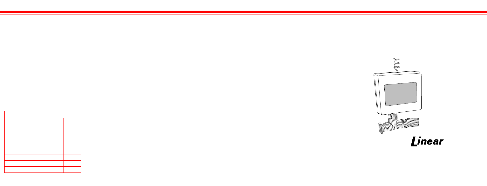
D-8C & D-8CW
Eight Channel
Digital Security Receiver
Code Setting
Instructions
D-8CW SHOWN
A NORTEK COMPANY
2055 Corte Del Nogal
Carlsbad, CA 92009
(619) 438-7000 • (800) 421-1587
CA (800) 321-1845 • FAX (619) 438-7043
Customer/Technical Service: (800) 392-0123
 Loading...