

Page 1
D-22D
CODING SWITCH IN
TWO-CHANNEL RECEIVER
SET KEYS 3-8 TO
ANY VALID CODE
D-22D CODING SWITCH
MATCH CODE
ON KEYS 3-8
SET KEY
2 OFF
KEY 1 IS
UNUSED
KEYS 1 & 2
ARE UNUSED
DIGITAL
TRANSMITTER
Code Setting
Instructions
(619) 438-7000 • FAX (619) 438-7043
USA & Canada (800) 42 1- 15 87 & (800) 392-012 3
Toll Free FAX (800) 46 8- 13 40
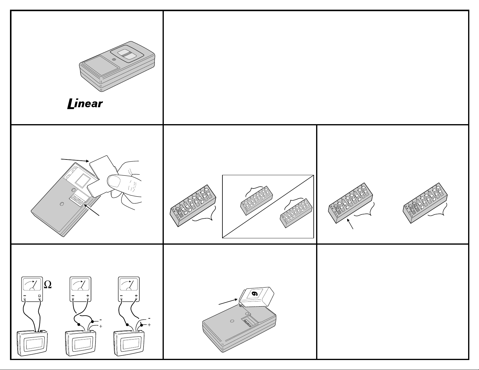
STEP 1
door located on the back of the transmitter case. Identify the
coding swit ch and note that it has eight positio ns, with ON and
OFF clearly marked.
Locate coding switch.
REMOVE BATTERY
ACCESS DOOR
Remove the battery access
CODING
SWITCH
TRANSMITTER DESCRIPTION
The D-22D is a two -button, two-channe l hand-held digital rad io
transmitter with a special lock-out feature. The transmitter can
perform a variety of remote switching tasks when used with any of
Linear’s Standard Digital “D” Series Receivers. Typically the
D-22D is used in wireless or hybrid wireless/hardwire security
systems.
The transmitter is powered by a 9-volt battery. Pressing either
button will send a “Channel 1" signal, pressing both buttons will
send a ”Channel 2" signa l. Hold but tons for at least 2 s econds
to activate the transmitter. The red LED on the face of the
transmitter will glow as the unit transmits and the receiv er with the
matching digital code will activate.
The Standard Digital radio format provides up to 256 different
digital codes. The code is set using the 8-position coding switches
in the transmitter and receiver.
STEP 2A
combination of OFF /ON co des an d set them on swit ch ke ys 2- 8 in
the transmitter Match the same code on switch keys 2-8 in the
receiver. Set receiver switch key 1 to OFF for the receiver to
activate from
switch key 1 to ON for the receiver to activate only when
transmitte r b utt o ns ar e p re ssed (Cha nn el 2 ).
D-22D CODING SWITCH
KEY 1 IS
UNUSED
Coding for single-channel receivers.
either
transmitter button (Channel 1). Set receiver
SET KEYS
2-8 TO ANY
CODE
CODING SWITCHES IN RECEIVER
RECEIVER FOR
CHANNEL 1
MATCH
2-8
SET
1 OFF
RECEIVER FOR
CHANNEL 2
TRIGGERS FROM
EITHER BUTTON
SET
1 ON
Pick any valid
both
MATCH
2-8
TRIGGERS FROM
BOTH BUTTONS
D-22D transmitter switch key 1 is unus ed and can be set in
any position. The transmitter pushbuttons control the signal that
would normally be controlled by switch key 1. Pressing either
pushbutton sends a signal as if switch key 1 is O FF. Pre ssing both
pushbutt ons se nd s a sig na l as i f sw it ch ke y 1 is ON .
✶ CAUTION: All Standard Digital transmitters and receivers should be
recoded prior to installation and operation.
In order to avoid the possibility of duplicating codes in adjacent
systems, factory set codes should not be used. In addition, among
the valid codes availabl e, fo ur othe rs sho uld not be use d. These
include: all keys set ON or OFF and keys set in an alternating
ON/OFF or OFF/ON pattern.
The D-22D will transmit as long as a pushbutton is pressed.
Depending on condi tions (interferenc e, obstacles and di stance to the
receiver) the r eceiver outpu t may or may no t stay activ ated for as
long as the transmitter is sending a signal.
✶ CAUTION: If using two receivers, be sure they are located at least 10 feet
apart.
STEP 2B
Coding for two-channel receivers.
Pick any
combination of OFF /ON co des an d set them on swit ch ke ys 3- 8 in
the receiver. Match the same code on switch keys 3-8 in the
transmitter. Set the
transmitter
switch 2 to OFF. Either button will
activate Channel 1, both buttons will activate Channel 2.
2-Channel receiver switch keys 1 & 2 are unused a nd can be
set in any position.
STEP 3
Test the equipment.
Connect the receiver to its power
source. With relay output receivers, listen for the relay click when
the transmitter is activated. A multi-meter can be used to detect
activation of relay and solid state output receivers. Operate the
transmitter from various locations to determine the radio range.
DCV DCV
COMMON
MEASURE
RESISTANCE
NORMALLY
OPEN
RELAY
OUTPUT
RECEIVER
OUTPUT
MEASURE
VOLTAGE
VOLTAGE
OUTPUT
RECEIVER
POWER
OUTPUT
MEASURE
VOLTAGE
RECEIVER
POWER
SHORT
-TO-
COMMON
OUTPUT
The battery should last 12 to 18 month s with normal u se. When
BATTERY REPLACEMENT
the red LED lights dimly, or not at all when transmitting, the battery
needs to be replace d. R em o ve the battery access door to change
the battery. Any type of 9-volt battery can be used. Replace the
battery do or an d f oam bat t ery pa d whe n f in ish ed .
REPLACE BATTERY WITH
FRESH 9-VOLT BATTERY
This Linear product is warranted against defects in material and workmanship for twelve (12) months. The
Warranty Expiration Date is labeled on the product.
buy direct from Linear or through Linear’s normal distribution channels.
to consumers.
any.
There are no obligations or liabilities on the part of Linear corporation for consequential damages
arising out of or in connection with use or performance of this product or other indirect damages with
respect to loss of property, revenue, or profit, or cost of removal, installation, or reinstallation.
warranties, including implied warranties for merchantability and implied warranties for fitness, are valid only until
Warranty Expiration Date as labeled on the product.
warranties express or implied.
For warranty service on Linear equipment return product, at sender’s expense to:
Linear Corporation Repairs Department
2580 Pioneer Avenue, Suite C
Vista, CA 92083
IMPORTANT !!!
Linear radio controls provide a reliable communications link and fill an important need in portable wireless
signalling. However, there are some limitations which must be observed.
For U.S. installations only: The radios are required to comply with FCC Rules and Regulations as Part 15
✶
devices. As such, they have limited transmitter power and therefore limited range.
A receiver cannot respond to more than one transmitted signal at a time and may be blocked by radio signals
✶
that occur on or near their operating frequencies, regardless of code settings.
Changes or modifications to the device may void FCC compliance.
✶
Infrequently used radio links should be tested regularly to protect against undetected interference or fault.
✶
A general knowledge of radio and its vagaries should be gained prior to acting as a wholesale distributor or
✶
dealer, and these facts should be communicated to the ultimate users.
Copyright © 1994 Linear Corporation 200858 B
LINEAR LIMITED WARRANTY
This warranty extends only to wholesale customers
Consumers should inquire from their selling dealer as to the nature of the dealer’s warranty, if
This Linear Corporation Warranty is in lieu of all other
Linear does not warrant this product
who
All implied
 Loading...