

Page 1
CPDM-1
Digital
Modulator
Converts the access system’s
camera video signal to a
UHF or CATV channel television signal
Installation Instructions
(760) 438-7000 • FAX (760) 438-7043
USA & Canada (800) 421-1587 & (800) 392-0123
Toll Free FAX (800) 468-1340
www.linearcorp.com
PRODUCT DESCRIPTION
The Model CPDM-1 Digital Modulator converts any baseband
NTSC video and audio signal to a selected UHF or Ultraband
CATV channel. A quartz crystal reference oscillator and PLL
circuitry ensure drift-free performance.
The modulator can be used to convert video signals from
Linear’s access control systems to UHF or CATV signals that
can be viewed on a standard television set at the installation.
The output channel number is selected using the PROGRAM
button. A television connected to the modulator’s output
will receive the signal when the television is tuned to the
modulator’s programmed channel.
NOTE: Linear’s access control systems can provide video
signals for the modulator from the system’s camera. Audio
signals from the system’s camera are NOT available.
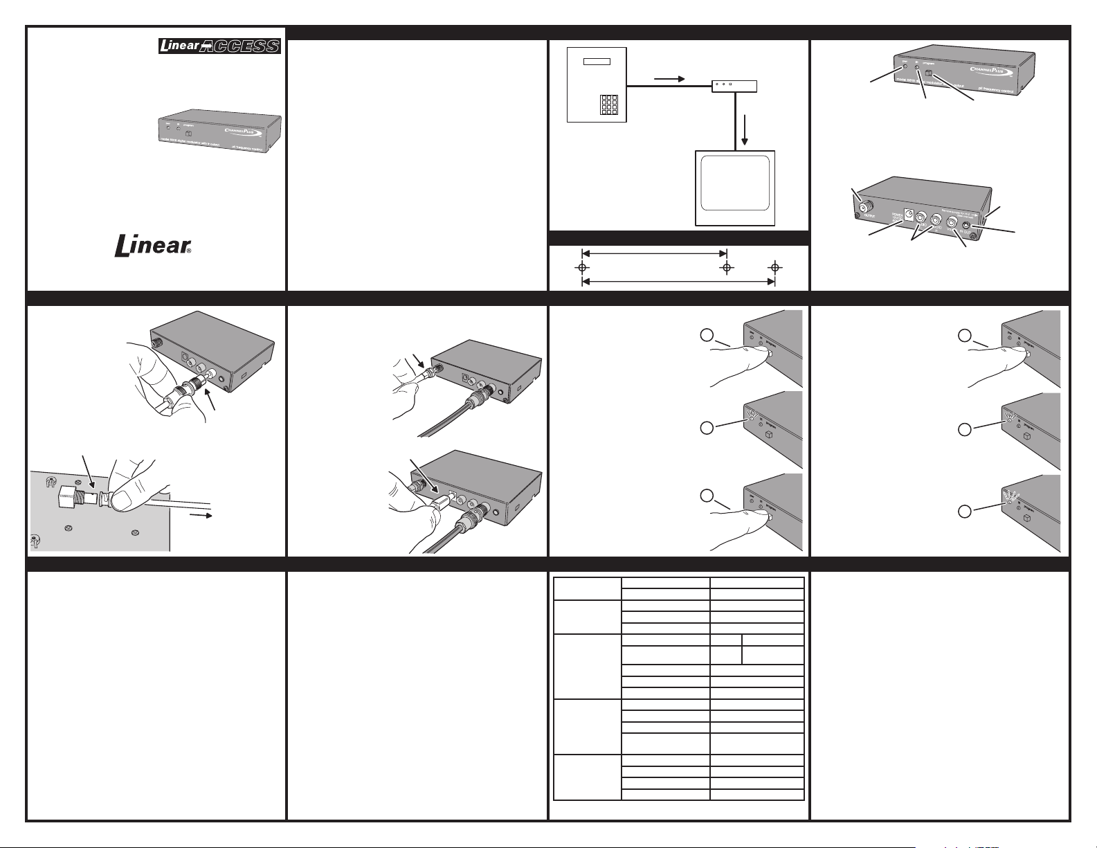
TYPICAL INSTALLATION COMPONENT LOCATIONS
VIDEO
SIGNAL
UP TO 150 FEET
RG-59 COAX
ACCESS
CONTROL
SYSTEM
TELEVISION
SET
MOUNTING TEMPLATE
TO HANG WITH CONNECTORS ON THE SIDE
TO HANG WITH CONNECTORS ON THE TOP OR BOTTOM
MODEL CPDM-1
MODULATOR
UP TO 25 FEET
RG-6 COAX
1-1/2"
RF
SIGNAL
2"
POWER
INDICATOR
LIGHTS WHEN
POWER IS APPLIED
RF OUTPUT
CONNECTOR
MODULATED RF OUTPUT
CONNECTS TO
A TELEVISION
POWER INPUT
CONNECTOR
CONNECTS TO POWER
FROM THE AC ADAPTER
IR INDICATOR
LIGHTS WHEN AN
INFRARED SIGNAL IS
REPEATED FROM AN
IR TARGET ACCESSORY
AUDIO INPUT
CONNECTORS
STEREO INPUTS FOR
CONNECTION TO AN AUDIO
SOURCE (USE BOTH JACKS
FOR MONAURAL)
PROGRAM
BUTTON
SELECTS THE
MODULATOR'S
CHANNEL
TERMINATES VIDEO
INPUT WITH A 75 OHM LOAD
(REMOVE IF VIDEO SIGNAL
IS TERMINATED AT
ANOTHER LOCATION)
VIDEO INPUT
CONNECTOR
COMPOSITE VIDEO
INPUT FOR CONNECTION
TO VIDEO SOURCE
TERMINATION
CONNECT MODULATOR VIDEO INPUT CONNECT MODULATOR OUPUT & POWER PROGRAM MODULATOR CHANNEL DISPLAY THE MODULATOR CHANNEL
FOR THE VIDEO SIGNAL, USE
RG-59 COAX CABLE WITH
BNC CONNECTORS
ON EACH END
CONNECT THE CABLE
TO THE VIDEO OUTPUT
JACK ON THE ACCESS
CONTROL SYSTEM
USE THE BNC-TO-RCA
ADAPTER (PROVIDED)
TO CONNECT THE
VIDEO CABLE TO THE
MODULATOR'S
VIDEO INPUT
TO
MODULATOR
FOR THE RF SIGNAL, USE RG-6 COAX CABLE
WITH "F" CONNECTORS ON EACH END
CONNECT RG-6 COAX TO THE
MODULATOR'S OUTPUT CONNECTOR
CONNECT THE OTHER END
OF THE RG-6 COAX TO
THE TELEVISION SET
OR DISTRIBUTION SYSTEM
INSERT THE AC ADAPTER
PLUG INTO THE MODULATOR'S
POWER CONNECTOR
PLUG THE AC ADAPTER
INTO AN UN-SWITCHED
AC OUTLET
TROUBLESHOOTING SELECTING HRC OR IRC FREQUENCIES SPECIFICATIONS
NO PICTURE
Verify that the video source is on and is producing a video signal. Check that the TV and
the modulator are tuned to the same channel. For example, if the modulator is
broadcasting on UHF channel 16, make sure the TV is on UHF 16 rather than CATV 16.
UHF 16 and CATV 16 are at different frequencies.
WEAK MODULATOR UHF CHANNEL
If the TV has a separate UHF input, be sure that it is connected.
HERRINGBONE INTERFERENCE ON MODULATOR CHANNEL (DIAGONAL LINES)
You may have chosen a channel number that is not completely vacant. Distant UHF
stations may be un-watchable, but will cause interference if you try to create a new
channel at the same frequency. Also, cable companies often have extra signals where
there should be none. Try moving the modulator channel to another number. You may
have to add a low pass filter to remove cable company noise.
HERRINGBONE INTERFERENCE ON MANY CHANNELS
(DISAPPEARS WHEN YOU REMOVE THE MODULATOR)
The high output of the modulator can overdrive many RF amplifiers. Reduce the RF
output using an attentuator.
NO COLOR ON MODULATOR CHANNEL
You may have chosen the incorrect cable standard. Not all televisions can accomodate
the 1.25 MHz frequency difference between H and I cable standards. See the next step.
CHANGING MODULATION STANDARDS
Most cable services use IRC frequency assignments.
setting for the modulator.
TV appears to search for the "house channels", the modulator can be
reprogrammed to use HRC assignments.
TO SELECT HRC FREQUENCIES
ENTER:
98
BEFORE PROGRAMMING THE
MODULATOR CHANNEL
However, if the cable service uses HRC or the
TO SELECT IRC FREQUENCIES
BEFORE PROGRAMMING THE
This is the default
ENTER:
99
MODULATOR CHANNEL
VALID CHANNELS:
UHF CHANNELS 14-46
CATV CHANNELS 65-125
INVALID CHANNELS:
CATV CHANNELS 95-99
EXAMPLE FOR CHANNEL 67:
1. PRESS PROGRAM BUTTON SIX TIMES
2. WAIT FOR POWER INDICATOR TO LIGHT
3. PRESS PROGRAM BUTTON SEVEN TIMES
4. WAIT FOR POWER INDICATOR TO LIGHT
5. DONE
EXAMPLE FOR CHANNEL 120:
1. PRESS PROGRAM BUTTON ONE TIME
2. WAIT FOR POWER INDICATOR TO LIGHT
3. PRESS PROGRAM BUTTON TWO TIMES
4. WAIT FOR POWER INDICATOR TO LIGHT
5. PRESS PROGRAM BUTTON TEN TIMES
(PRESSING TEN TIMES EQUALS "ZERO")
6. WAIT FOR POWER INDICATOR TO LIGHT
7. DONE
NOTES:
SELECT A CHANNEL THAT IS AT LEAST TWO
CHANNELS AWAY FROM AN EXISTING CHANNEL
IF AN INVALID CHANNEL IS ENTERED,
THE POWER LED WILL FLASH FOR ONE
SECOND, THEN THE MODULATOR WILL
RETURN TO THE PREVIOUS SETTING
INPUTS
VIDEO
PERFORMANCE
VIDEO
AUDIO
DIFFERENTIAL GAIN 4%
DIFFERENTIAL PHASE <4°
SIGNAL/NOISE 55 dB
STANDARD UHF CATV
CHANNEL RANGES 14-64 65-125
RF OUTPUT
OUTPUT LEVEL +25 dBmV (90dBuV)
IM DISTORTION -60 dBC
ALTERNATE CHANNEL -45dBC @ 12 MHz
OUTPUT CURRENT 600 mA
POWER SUPPLY
OUTPUT VOLTAGE 15 VDC
INPUT VOLTAGE 105-125 VAC
POWER
CONSUMPTION
HEIGHT 1.0 in (2.5 cm)
PHYSICAL
WIDTH 4.6 in (11.7 cm)
DEPTH 3.2 in (8.1 cm)
WEIGHT 9.6 oz (0.273 kg)
ENTER
1
2
WAIT
ENTER
3
1 V p-p @ 75 Ω
1 V rms @ 47 KΩ
5 WATTS
(EXCLUDING 95-99)
PRESS AND HOLD
PROGRAM BUTTON
WHILE APPLYING POWER
RELEASE THE PROGRAM
BUTTON WHEN THE POWER
INDICATOR LIGHTS
THE POWER INDICATOR WILL
BLINK TO COUNT THE PROGRAMMED
CHANNEL NUMBER
(10 BLINKS EQUALS NUMBER "0")
1
2
3
LINEAR LIMITED WARRANTY
This Linear product is warranted against defects in material and workmanship for twelve (12)
months. The Warranty Expiration Date is labeled on the product. This warranty extends only
to wholesale customers who buy direct from Linear or through Linear’s normal distribution
channels. Linear does not warrant this product to consumers. Consumers should inquire from
their selling dealer as to the nature of the dealer’s warranty, if any. There are no obligations
or liabilities on the part of Linear Corporation for consequential damages arising out of or in
connection with use or performance of this product or other indirect damages with respect to
loss of property, revenue, or profi t, or cost of removal, installation, or reinstallation. All implied
warranties, including implied warranties for merchantability and implied warranties for fi tness,
are valid only until Warranty Expiration Date as labeled on the product. This Linear Corporation
Warranty is in lieu of all other warranties express or implied.
All products returned for warranty service require a Return Product Authorization Number
(RPA#). Contact Linear Technical Service at 1-800-421-1587 for an RPA# and other important
details.
This device complies with Part 15 of the FCC Rules. Operation is subject to the following two
conditions: (1) This device may not cause harmful interference, and (2) this device must accept
any interference received, including interference that may cause undesired operation.
FCC classifi es this product under Part 15 of its rules as a “television interface device”. Systems
designed using television interface devices have the following legal requirements:
1) The modulated channel signal strength may not exceed 15.56 dBmV at any television.
Federal Regulation 47CFR15.115(b)(1)(i).
2) If an antenna is used in the system, the modulated channel signal strength may not exceed
-51dBmV at the antenna input port. Federal Regulation 47CFR15.115(c)(4).
FCC NOTICE !!!
INSTALLATION REQUIREMENTS
JUMPER
IR OUTPUT
CONNECTOR
CONNECTS TO
IR EMITTER
ACCESSORY
221695 A
 Loading...