

Page 1
CC3008
Air Conditioning
Protection System
Installation Instructions
For use with All
Air Conditioning Systems
USA & Canada (800) 421-1587 & (800) 392-0123
(760) 438-7000 - Toll Free FAX (800) 468-1340
www.linearcorp.com
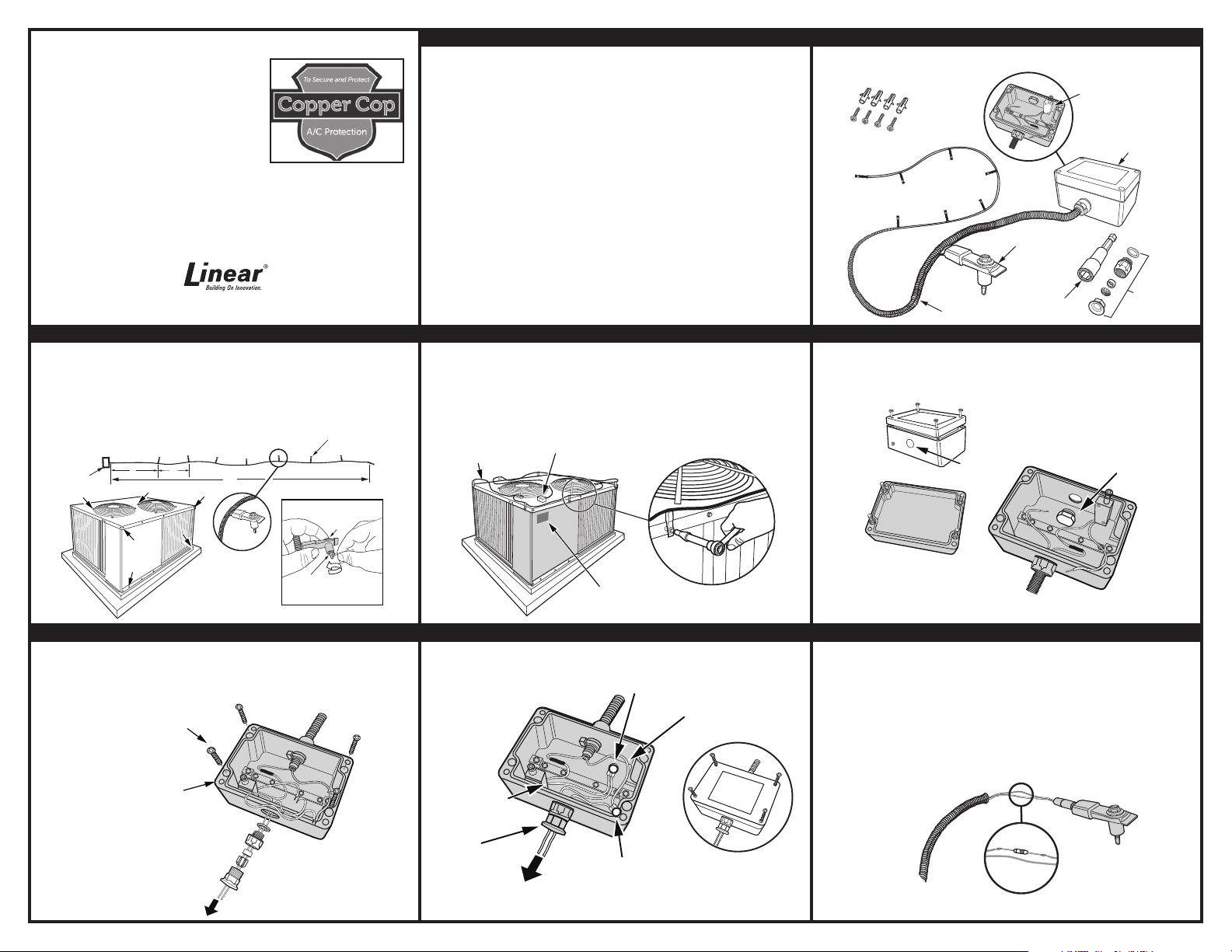
3. SENSOR CLIP LOCATIONS
Begin by stringing out the 27’ cable strand. Place the cable strand and Control Box on
top of air conditioning unit and determine possible screw points where Sensor Clips
can be installed. The diagram below shows suggested clip locations. Air conditioner
units will vary so select a pattern of placement that best suits the installation. To
prepare for installation, REMOVE the tie wrap from each Sensor Clip used as shown.
27´ CABLE STRAND WITH 8 SENSOR CLIPS SPACED
AT 3´ INTERVALS
6´
CONTROL
BOX
3´
SUGGESTED SENSOR CLIP
LOCATION POINTS
27´
SENSOR
CLIP CLOSE UP
UNSCREW TIE WRAP FROM
SENSOR, COUNTER CLOCKWISE
BEFORE INSTALLING
SENSOR
CLIPS (8)
HOLD HEAD OF
SCREW WITH
FINGER
1. PRODUCT DESCRIPTION
Copper Cop Air Conditioning Protection System is designed to detect theft of copper
components typically found in high-end commercial air conditioning units. The product
is a normally closed alarm loop. Unscrewing a Sensor Clip, cutting the cable, or
opening with the Control Box will violate the loop. The system can either be hardwired
to an alarm control panel or connected to a wireless transmitter (not included) placed
inside of the Control Box.
Components of the Copper Cop detector include a Control Box and 27 feet of wire
covered in 3/8” diameter yellow corrugated plastic split wire loom. Each Copper Cop
detector includes 8 Sensor Clips. The fi rst Sensor Clip is positioned six feet from the
Control Box. From that point, additional Sensor Clips are placed at three foot intervals.
Each Sensor Clip has a #10 self tapping screw for mounting. The Sensor Clips can
be installed in pre-existing holes on the air conditioning unit frame structure using the
5/16” socket tool provided. If new holes are required, use a 1/8” diameter drill. The
Control Box is installed on the desired surface using 4 screws and anchors (provided).
IMPORTANT: Drilling holes is advisable only when necessary and if it is known
what is behind the panel being drilled. Linear is not responsible for any damage
to air conditioning systems.
4. SENSOR CLIP INSTALL ATION
Remove screws from the chosen locations of the air conditioning unit and then install
the Sensor Clips at each of these points using the 5/16” socket tool (provided). If
additional holes are needed to position Sensor Clips in more convenient locations,
drill them now with a 1/8” drill bit. Finish mounting the remaining Sensor Clips. It is
recommended that ALL clips be installed for maximum protection. Install the warning
sign in a high visibility location on air conditioner as an added deterrent.
8 SENSOR CLIP
STRAND INSTALLED
CONTROL
BOX
COPPER COP
WARNING SIGN
2. COMPONENTS KIT
The Copper Cop product includes the following components:
CONTROL
BOX SCREWS
AND ANCHORS
8 SENSOR CLIPS PER STRAND AT
3’ INTERVALS
27’ CABLE STRAND
SENSOR CLIP
5/16” HEX
SOCKET
TAMPER SWITCH
INSIDE CONTROL
BOX
CONTROL
BOX
STRAIN
RELIEF
ASSEMBLY
5. CONTROL BOX PREPARATION
When hard wire connecting to an alarm control panel, a strain relief is included for the
wires exiting the Control Box. To prepare for the strain relief, unscrew and remove the
hole plug from inside the Control Box.
REMOVE TOP OF
CONTROL BOX
TOP REMOVED
CONTROL BOX
PLUG
REMOVE
PLUG FROM
INSIDE BOX
6. CONTROL BOX INSTALLATION
FIRST run alarm panel wires through strain relief assembly and screw all parts
together. This will trap wires. THEN feed wires through hole in Control Box and thread
strain relief into hole. Use screws (provided) to mount Control Box to desired surface.
CONTROL BOX
MOUNTING
SCREWS (4)
CONTROL
BOX
FIRST RUN WIRES
THROUGH
STRAIN RELIEF
ASSEMBLY
TO ALARM
PANEL
THEN SCREW
STRAIN RELIEF INTO
CONTROL BOX
7. WIRE CONNECTIONS
Use appropriate type of wire connectors to connect the detector as shown in diagram
below. Reinstall the Control Box top and tighten screws.
CONTROL
BOX
WHITE
WIRE
STRAIN
RELIEF
TO ALARM
PANEL
CONNECTOR
CONNECTOR
YELLOW
WIRE
RE-ATTACH
CONTROL
BOX TOP
8. END OF LINE RESISTOR INSTALLATION
When connecting the detector to an alarm panel, an end-of-line resistor may be
required. It can be soldered into the line at the Sensor Clip farthest from the Control
Box. Pull wires out of loom. Separate coated wires from each other, then strip wire
jacket and solder in the correct value resistor. Complete installation by slipping wires
and resistor back into wire loom and loom into end of the Sensor Clip. NOTE: Refer
to alarm panel for resistor value.
STRIP WIRE AND
CONNECT RESISTOR
PULL BACK WIRE
LOOM TO EXPOSE
WIRES
INTO ONE WIRE
RESISTOR
SENSOR CLIP AT END
OF STRAND
Page 2
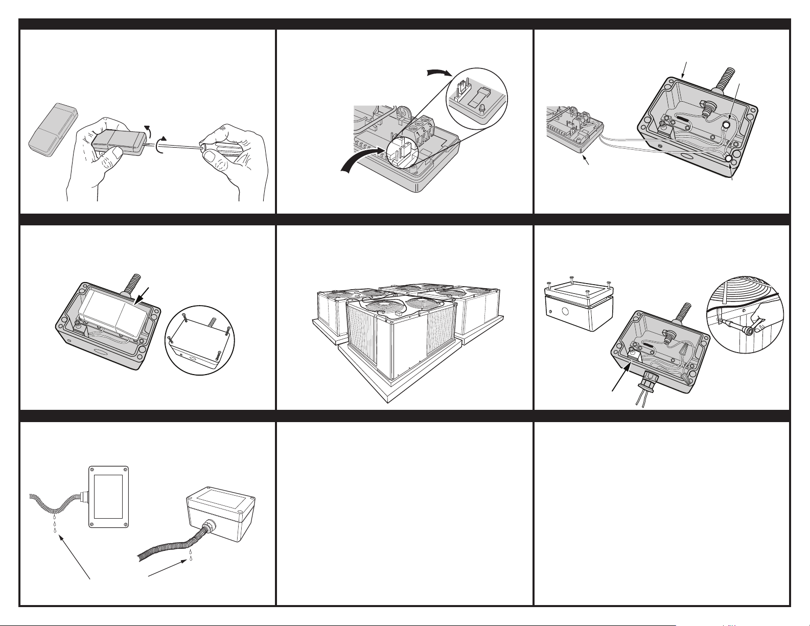
9. WIRELESS TRANSMITTER OPTION
Copper Cop can also be used with a stationary transmitter such as the Linear
DXS-31. Other transmitters that support an external contact input may also be used.
The DXS-31 will fi t inside the Copper Cop Control Box (inside free space dimension
of 3-1/4”x 2” x 1”).
DXS-31 TRANSMITTER
REMOVE THE CASE TOP BY TWISTING A
SMALL FLAT BLADE SCREWDRIVER IN THE
TOP CASE SLOT (ON THE THICK END OF THE
TRANSMITTER)
LIFT
10. TRANSMITTER JUMPER CONFIGURATION
Before wiring the DXS-31 transmitter to the Copper Cop Control Box, confi gure
jumper as shown to accommodate an external contact.
PUT JUMPER ON THE
MIDDLE PINS TO USE
AN EXTERNAL SWITCH
11. TRANSMITTER/CONTROL BOX HOOK-UP
Wire Copper Cop Control Box to DXS-31 transmitter to create a normally closed
circuit.
CONTROL
WIRE EXTERNAL
NORMALY CLOSED
CONTACTS TO
TERMINALS 1 & 2
BOX
CONNECTOR
TWIST
12. MOUNTING TRANSMITTER IN CONTROL BOX
After hooking up the wiring between the DXS-31 transmitter and the Copper Cop
Control Box, place the transmitter inside the Control Box. Re-assemble the Control
Box top and tighten the cover screws.
CONTROL
BOX
LOCATE DXS-31
TRANSMITTER IN
CONTROL BOX
RE-ASSEMBLE CONTROL
BOX TOP
15. CONTROL BOX MOUNTING TIPS
To prevent water wicking into Control Box, a drip loop can be created in the cable
before vertical mounting. When possible, it is recommended that the Control Box be
vertically mounted. If Control Box is horizontally mounted, allow for cable slack prior
to box for water drainage.
VERTICAL MOUNTING
OF CONTROL BOX WITH
DRIP LOOP IN CABLE.
WHEN HORIZONTALLY
MOUNTING CONTROL
MOISTURE WILL DRIP
OFF WIRE LOOM
BOX, ALLOW SOME
CABLE SLACK FOR
DRAINAGE PRIOR TO
ENTERING BOX
THIS IS THE FACTORY SET
JUMPER POSITION, IT
SELECTS THE INTERNAL
CONTACTS
13. MULTIPLE AIR CONDITIONER UNITS
If there are a number of air conditioning units in close proximity to each other, it will
require more than a single Copper Cop Kit. Plan on having ample kits for the project.
It is also recommended that all 8 Sensor Clips be used on a single air conditioning
unit for maximum protection.
NOTE: Each Copper Cop Kit will require an individual connection to the alarm panel.
NOTES
___________________________________________________________________
___________________________________________________________________
___________________________________________________________________
___________________________________________________________________
___________________________________________________________________
___________________________________________________________________
___________________________________________________________________
___________________________________________________________________
___________________________________________________________________
___________________________________________________________________
___________________________________________________________________
___________________________________________________________________
__________________________________________________________________
__________________________________________________________________
___________________________________________________________________
___________________________________________________________________
__________________________________________________________________
__________________________________________________________________
DXS-31
TRANSMITTER
CONNECTOR
14. TESTING SYSTEM
After installing and wiring the Copper Cop, to test the system REMOVE the Control
Box top. The tamper switch will open the circuit and alarm should sound. If it does
not, re-check all wire connections for shorts. Make appropriate corrections, then test
again. A second system test is to remove any one of the Sensor Clips. This should
open the circuit and activate the alarm.
CONTROL
BOX
REMOVING
CONTROL BOX
TOP WILL ACTIVATE
TAMPER SWITCH,
SETTING OFF ALARM
TAMPER
SWITCH
REMOVING
ANY SENSOR
CLIP WILL ACTIVATE
AN ALARM
LINEAR LIMITED WARRANTY
This Linear product is warranted against defects in material and workmanship for twenty-four (24) months. This
warranty extends only to wholesale customers who buy direct from Linear or through Linear’s normal distribution
channels. Linear does not warrant this product to consumers. Consumers should inquire from their selling dealer
as to the nature of the dealer’s warranty, if any. There are no obligations or liabilities on the part of Linear LLC for
consequential damages arising out of or in connection with use or performance of this product or other indirect
damages with respect to loss of property, revenue, or profi t, or cost of removal, installation, or reinstallation. All
implied warranties, including implied warranties for merchantability and implied warranties for fi tness, are valid only
until the warranty expires. This Linear LLC Warranty is in lieu of all other warranties express or implied.
All products returned for warranty service require a Return Product Authorization Number (RPA#). Contact Linear
Technical Services at 1-800-421-1587 for an RPA# and other impor tant details.
• Linear radio controls provide a reliable communications link and fi ll an important need in portable wireless
signaling. However, there are some limitations which must be observed.
• For U.S. installations only: The radios are required to comply with FCC Rules and Regulations as Part 15 devices.
As such, they have limited transmitter power and therefore limited range.
• A receiver cannot respond to more than one transmitted signal at a time and may be blocked by radio signals
that occur on or near their operating frequencies, regardless of code settings.
• Changes or modifi cations to the device may void FCC compliance.
• Infrequently used radio links should be tested regularly to protect against undetected interference or fault.
• A general knowledge of radio and its vagaries should be gained prior to acting as a wholesale distributor or
dealer, and these facts should be communicated to the ultimate users.
Copyright © 2012 Linear Corporation 233768 A
IMPORTANT !!!
 Loading...