

Page 1

BioRead 1000 Series
Installation Manual
BioRead 1000 is the only biometric with a model specifically designed for small standalone applications – IEI’s strength in the marketplace.
Enrollment also is SIMPLE. There is no software or PC needed. A low cost hand-held
programmer quickly enrolls users in a fraction of the time it takes competitive products.
Key Features
Finger only – no card required
No PC or software needed
Separate door controller for increased
security-stand alone applications
90 templates
Add/delete with hand-held programmer
Authenticate in less than 2 seconds
Option for Wiegand output
Service Company Contact Information
company:
BioRead 1000
TABLE OF CONTENTS
Subject Page
BR-1000 Package ------------------------------------ 2
Using as a
Wiring Reader to Door Controller --------------------- 5
Relay Operation and wiring Door Controller --------- 6
BR-1100 Package ------------------------------------ 10
Using as a
Access Panel ---------------------------------------------- 12
IEI eMerge ---------------------------------------------- 13
IEI HUBMAXII System ---------------------------------- 14
Exterior Installation ------------------------------------ 19
Specifications ----------------------------------------- 20
BioRead Access Systems ------------------------------- 21
contact name:
telephone:
email:
website:
Stand-Alone Device
Front-End Reader
-------------------------- 11
------------------------ 3
p/n 6035000 rev 2.0
Page 2
BioRead 1000 Series
g
Installation Manual
BioRead 1000 Series
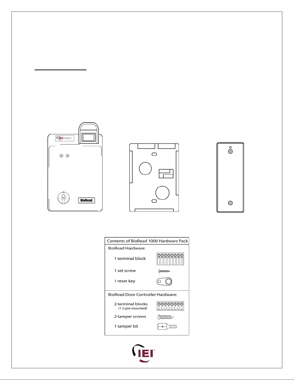
BR-1000 Package
Package includes:
1 BioRead 1000 biometric fingerprint reader
1 Mounting Bracket (surface-mount)
1 BioRead Door Controller
1 BioRead 1000 Hardware Pack – see below
1 Installation Manual
BioRead 1000
Reader
Mountin
Bracket
BioRead
Door Controller
p/n 6035000 rev 2.0 Page 2 of 22
Page 3
BioRead 1000 Series
Installation Manual
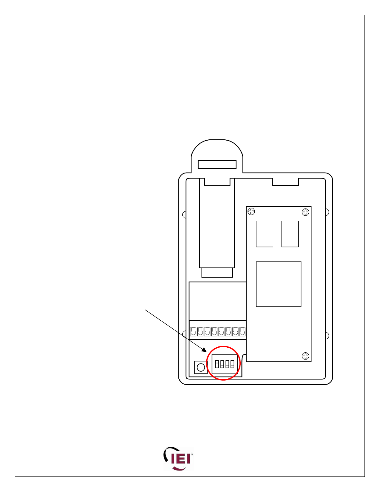
The BioRead™ fingerprint reader can be used as a stand-alone device when used
with the BioRead Door Controller.
If the BioRead is being used as a stand alone device dipswitch 1 at the rear of the
unit must be set to ON. Dipswitches 2-4 must be set to OFF.
See the illustration below.
Using as a Stand Alone device (model BR-1000)
Dipswitch 1 must be set
to ON when BioRead™ is
used with the BioRead
Door Controller.
Dipswitches 2-4 are set
to OFF
BioRead™ fingerprint reader
(rear view)
p/n 6035000 rev 2.0 Page 3 of 22
Page 4
BioRead 1000 Series
Installation Manual
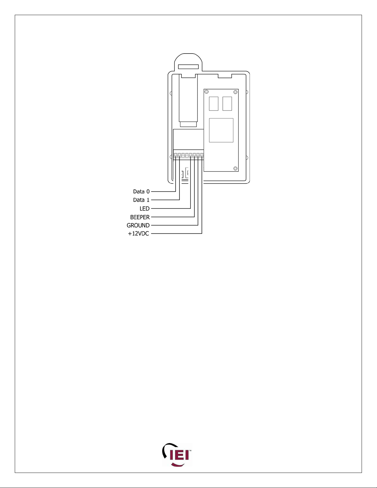
Mounting the Reader:
The BioRead Reader mounts on a single-gang electrical box.
1. Remove the screw from the bottom of the unit using a Phillips screwdriver.
2. Remove back mounting plate by pulling gently from inside the cable feed-through hole.
3. Insert the cable from the wall through the hole in the back plate, and then mount the back plate
to the electrical box with the supplied screws.
4. Remove the plug-in connector from the unit and connect the cable as per wiring instructions on
next page.
5. Plug the connector back into the unit.
IMPORTANT: Confirm wiring before applying power as 12VDC applied to wrong pin
can damage the unit.
6. Attach the main unit to the back plate by tilting the bottom of the unit toward you, then sliding
the top of the unit over the back plate.
7. Secure the main unit to the back plate with the screw removed in Step 1.
LED and BEEPER control:
The LED line is used to control the LED on the right side of the unit. This LED is normally RED and will
turn GREEN when the line is pulled LOW.
The BEEPER line is used to activate the unit’s internal beeper. The beeper will sound if the line is pulled
LOW.
p/n 6035000 rev 2.0 Page 4 of 22
Page 5
BioRead 1000 Series
Installation Manual
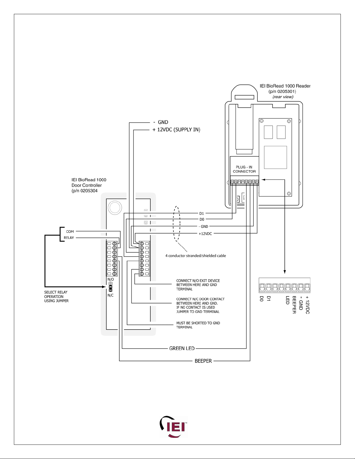
Wiring to the Stand Alone Door Controller
(Model
BR-1000 includes reader and door controller)
Connect the BioRead to the BioRead Door Controller as shown above.
p/n 6035000 rev 2.0 Page 5 of 22
Page 6
BioRead 1000 Series
Installation Manual
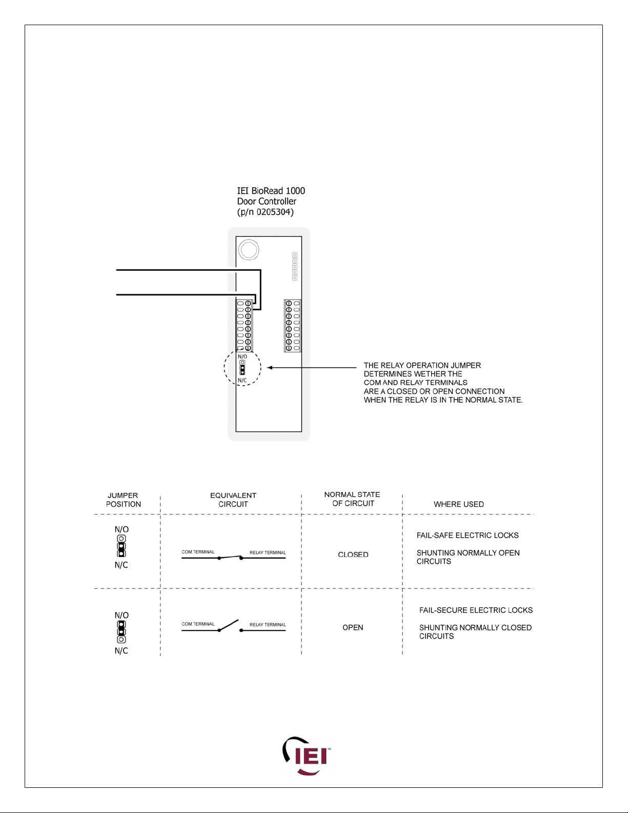
Relay Operation of the Stand Alone Door Controller
The illustration and chart below indicate how the dry-c
perates. Output connection is made via the RELAY and COM screw terminals as illustrated below. The
o
ature of the output itself is determined through a two-position jumper located on the circuit board.
n
he chart below shows that while the COM terminal is the same in both jumper positions the RELAY
T
terminal changes between the NO (normally-open) and NC (normally-closed) positions.
ontact relay of the Stand Alone Door Controller
p/n 6035000 rev 2.0 Page 6 of 22
Page 7
BioRead 1000 Series
Installation Manual
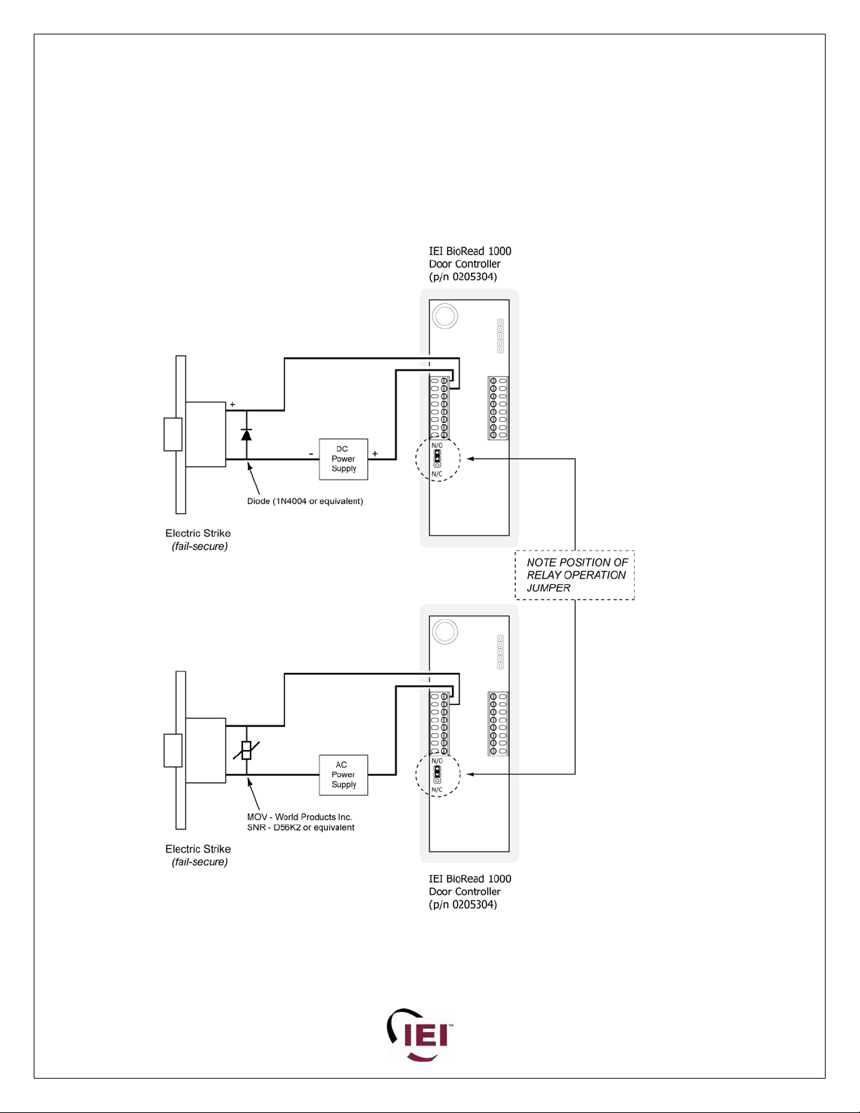
Wiring the Stand Alone Door Controller to a fail-secure electric lock.
In the diagrams below is illustrated how a FAIL - SECURE electric strike is wired.
The differences between the diagrams are in the choice of voltage for the electric strike. Also, notice that
each type of voltage (AC or DC) requires its own protection for inducted or transient voltage effects. I
the diagram where DC is used you will find a diode and in the diagram where AC is used you will find
MOV. Whichever type of voltage you choose for the lock, do not forget to install the cor
across the voltage inputs of the lock.
NOTE:
THE DIODE OR MOV MUST BE INSTALLED AS CLOSE TO THE LOCK AS POSSIBLE. INSTALLING
THE MOV OR DIODE ACROSS THE OUTPUT TERMINALS OF THE DOOR CONTROLLER WILL NOT
PROPERLY PROTECT THE BIOREAD DOOR CONTROLLER.
rect component
n
an
p/n 6035000 rev 2.0 Page 7 of 22
Page 8

BioRead 1000 Series
Installation Manual
Wiring the Stand Alone Door Controller to a fail-safe electric lock.
In the diagrams below is illustrated how a FAIL – SAFE electromagnetic lock is wired.
The differences between the diagrams are in the choice of voltage for the electric strike. Also, notice that
each type of voltage (AC or DC) requires its own protection for inducted or transient voltage effects. In
the diagram where DC is used you will find a diode and in the diagram where AC is used you will find an
MOV. Whichever type of voltage you choose for the lock, do not forget to install the correct component
across the voltage inputs of the lock.
NOTE:
THE DIODE OR MOV MUST BE INSTALLED AS CLOSE TO THE LOCK AS POSSIBLE. INSTALLING T
OR DIODE ACROSS THE OUTPUT TERMINALS OF THE DOOR CONTROLLER WILL NOT PROPERLY
PROTECT THE BIOREAD DOOR CONTROLLER.
HE MOV
p/n 6035000 rev 2.0 Page 8 of 22
Page 9

BioRead 1000 Series
Installation Manual
Notes:
1. The relay activation time is fixed at 7 seconds.
2. If a door contact is used, it is connected to the DC pin of the BioRead Door
Controller.
3. The Door Contact will ensure that the Relay Activation Time is stopped.
4. The BioRead Door Controller turns the RIGHT LED of the BioRead reader
GREEN to indicate relay activation. The LEFT LED on the BioRead turns
GREEN after a valid fingerprint authentication.
5. Relay can switch up to 2A@24VDC. Do not switch high current/voltage
through this relay.
ee Operator Instructions for programming BioRead with the Hand-Held Programmer.
S
p/n 6035000 rev 2.0 Page 9 of 22
Page 10

BioRead 1000 Series
g
Installation Manual
BioRead 1000 Series
BioR
Packa
1 BioRe
1 Moun
1 Bio
1 Instal
ge includes:
Read 1100 Hardware Pack – see below
ead 1100 Package
ad 1000 biometric fingerprint reader 12VDC
ting Bracket (surface-mount)
lation Manual
BioRead 1000
Reader
Mountin
Bracket
p/n 6035000 rev 2.0 Page 10 of 22
Page 11

BioRead 1000 Series
A
-
Installation Manual
Using as a 26-bit Wiegand front-end reader (model BR-1100)
The BioRead™ fingerprint reader ca
reader for an IEI HubMaxII, Hub MinimaxII, eMerge system or
as 26-bit W
If the BioRead is being used as a front-end reader
all four dipswitches at the rear of
See the illustration below.
n be used as the front-end
iegand front-end reader for another access control system.
the unit must be set to OFF.
ll four dipswitches are
set to OFF when
BioRead™ is used as a 26
bit Wiegand front-end
reader
BioRead™ fingerprint reader
(rear view)
p/n 6035000 rev 2.0 Page 11 of 22
Page 12

BioRead 1000 Series
Installation Manual
to the front-end reader port of an access control panel
Wiring the IEI BioRead™ fingerprint reader
p/n 6035000 rev 2.0 Page 12 of 22
Page 13

BioRead 1000 Series
Installation Manual
Wiring the IEI B Access Control ioRead™ fingerprint reader to an IEI eMerge
Module
p/n 6035000 rev 2.0 Page 13 of 22
Page 14

BioRead 1000 Series
Installation Manual
Wiring the IEI BioRead™ fingerprint reader to a HubMaxII or MinimaxII
p/n 6035000 rev 2.0 Page 14 of 22
Page 15

BioRead 1000 Series
Installation Manual
BioRead™ User Capacity
When a user is programmed into the BioRead, that user occupies a place in its memory
known as a User Location.
The IEI BioRead has a 98 User Capacity, which breaks down as:
User Locations 1 thru 90 – fingerprint users only
User Locations 91 thru 98 – Bypass Key users only
How the BioRead™ 1000 fingerprint reader works
when used as a Weigand front-end reader to an IEI eMerge system.
o If a credential is presented to the BioRead 1000, and recognized as a programmed
user, the BioRead will then send the user location number of that credential in
26-bit weigand format through the Data 0 and Data 1.
How the BioRead™ 1000 fingerprint reader works
when used as a front-end reader to an IEI MaxII system.
o The SSIM will convert the weigand data into a format that the MaxII system will
work with
(known as IM FORMAT)
.
o The MaxII system will interpret the data from the SSIM interface module as CARD
DATA.
o This means that the User Location Number sent from the BioRead will only be
interpreted by the MaxII as CARD DATA.
Operation Example:
1. The Right Index Finger of John Smith has been programmed into the BioRead at user location 01.
2. John Smith presents his Right Index Finger to the BioRead.
3. The BioRead recognizes John’s finger.
4. This is indicated by the left hand LED on the BioRead™ turning green.
5. The BioRead sends the number 01 out the D0 and D1 data lines in 26-bit weigand format.
6. The SSIM board translates the 26-bit data from the BioRead into MaxII format.
7. The MaxII sees the CARD NUMBER 01 presented to the front-end reader port.
8. The MaxII recognizes that a CARD NUMBER and initiates an authorized access.
9. This is indicated by the right hand LED on the BioRead turning green.
This means that in order for the BioRead to work with the MaxII system:
o Each user must be programmed into the BioRead, either with a fingerprint or
Bypass Key.
o Each user must also be programmed into the MaxII system.
Users programmed into the MaxII system must be programmed as card
o
users, with the number of their BioRead™ Memory Slot programmed as
their encoded card number.
p/n 6035000 rev 2.0 Page 15 of 22
Page 16

BioRead 1000 Series
Installation Manual
Setting the Site Code on the SSIM board
If you wish to employ a site c
ode with the BioRead, remember to properly set the SSIM
board by:
. Set dipswitches 1-8 to reflect the Site Code that you defined into the handheld
1
programmer of the BioRead.
. Set dipswitch 9 to ON. This will enable the Site Code feature of the SSIM. If this switch
2
is OFF there will be no Site Code verification bet
ween the BioRead and the SSIM.
The SSIM board is sold with an installation manual that also has
a Site Code Chart,
which translates a decimal number (like 11) into a binary number that can be set using
the dipswitches on the SSIM board.
NOTE: THE SITE CODE (aka FACILITY CODE) THAT THE IEI BIOREAD USES IS
THE LAST 3 DIGITS OF THE PASSWORD PROGRAMMED IN
HAND-HELD PROGRAMMER
SEE THE BIOREAD SETUP AND OPERATOR GUIDE (6035001) FOR
INFORMATION ON SETTING UP THE HAND HELD PROGRAMMER
TO THE
p/n 6035000 rev 2.0 Page 16 of 22
Page 17

BioRead 1000 Series
Installation Manual
p/n 6035000 rev 2.0 Page 17 of 22
Page 18

BioRead 1000 Series
Installation Manual
p/n 6035000 rev 2.0 Page 18 of 22
Page 19

BioRead 1000 Series
BioRead 1000 Series
Installation Manual
Installation Manual
Exterior Installation
When mounting the IEI BioRead in an exterior environment the BR-1190 reader cover is
required.
If the temperature is likely to drop below 40F (4C),
IEI recommends the installation of a heater kit, as shown below.
The model number of the Heater Kit is STI-6580, and is manufactured by:
Safety Technology International (STI) 800-888-4STI, www.sti-usa.com
Each of these components with is supplied with installation instructions.
The illustration below lays out the entire mounting scenario.
p/n 6035000 rev 2.0 Page 19 of 22
p/n 6035000 rev 2.0 Page 19 of 22
Page 20

BioRead 1000 Package
Installation Manual
Specifications
BioRead 1000 Fingerprint Reader
Electrical: 12VDC @ 300mA
Output: 26-bit Weigand
Operating
Temperature:
Size: 3 ¼” (w) X 4 ¾” (h) X 1 ½” (d)
Weight: 10 oz
Housing: High Impact Polycarbonate
Mounting: surface-mount to single gang electrical box
Sensor: optical with typically<2 and up to 4 second verification with 90 users programmed
Indicators:
Sounder: used for programming feedback and can be triggered externally
Cable:
-40F to +70F (-40C to +21C)
LED
Bi-Color Standard (red, green), 1X Authentication Indicator, 1X External Control Indicator
22AWG, 4 Conductor, Stranded, Overall Shield, Maximum 500 ft. to controller
BioRead 1000 Door Controller
Electrical: 12VDC @ 100mA
Output: dry-contact relay, configured as NO or NC via jumper setting
Size: 1 ¾” (w) X” (h) X 4 ” (d)
Mounting: surface-mount
Sounder: used for programming feedback and door ajar alarm
p/n 6035000 rev 2.0 Page 20 of 22
Page 21

BioRead 1000 Package
Installation Manual
BioRead Access Systems
Part Number Description
BioRead 1000
print Reader and
Door Controller
programmer
BioRead 1000
Fingerprint Reader
BR-1000
BR-1100
Finger
for stand alone applications
each system requires
provides a 26-bit Wiegand output
to an access control system
each system requires programmer
BR -1150 BioRead Door Controller
B
R-1170
Hand held
programmer with 5
bypass keys
BR-1175 Hand held programmer
BR-1180 Bypass Keys (5)
p/n 6035000 rev 2.0 Page 21 of 22
Page 22

BioRead 1000 Package
Installation Manual
Warranty Policy
International Electronics, I products to be free from defects in
nc. (IEI) warrants its
material and workmanship when they have been installed in accordance with the
manufacturer’s instru ified or tampered with. IEI does not
assume any responsib erson or property due to improper
care, storage, handling, a
ctions and have not been mod
y for damage or injury tilit o p
buse, misuse, normal wear and tear, or an act of God.
IEI’s sole responsibility is limited to the repair (at IEI’s option) or the replacement of the
defective product or part when sent to IEI’s facility (freight and insurance charges
prepaid) after obtaining IEI’s Return Material Authorization. IEI will not be
liab purchaser tal or consequential damages arising
le to the or any one else for inciden
from any defect in, or malfunction of, its products.
Except as stated above, IEI makes no warranties, either expressed or implied, as to any
matter whatsoever, including, and without limitation to, th condition of its products,
e
their merchantability, or fitness for any particular purpose.
Warra
nty Periods Are:
1-Year BioRead Access Systems
1 Year eMerge Series
2 Years Door Gard & Secured Series Products
2 Years LS Series
2 Years Glass Break
5 Years “e” Series Keypads
All products have date code labeling and/or serial number
labeling to determine the warranty period.
p/n 6035000 rev 2.0 Page 22 of 22
 Loading...