

Page 1
IMPORTANT SAFETY INSTRUCTIONS
CENTRAL CLEANING
SYSTEM INSTALLATION
INSTRUCTIONS
When using an electrical appliance, basic precautions
should always be followed, including the following:
READ ALL INSTRUCTIONS CAREFULLY
BEFORE USING THIS APPLIANCE
WARNING - To reduce the risk of fire, electrical shock or injury:
1. Electric shock could occur if system is operated on wet surfaces.
2. Do not allow to be used as a toy. Close attention is necessary when
used by children.
3. Use only as described in this manual. Use only manufacturer's
recommended attachments.
4. Do not put any object into openings. Do not use with any opening
blocked; keep free of dust, lint, hair, and anything that may reduce air
flow.
5. Keep hair, loose clothing, fingers, and all parts of body away from
openings and moving parts.
6. Do not pick up anything that is burning or smoking, such as cigarettes,
matches, or hot ashes.
7. Do not use without dust bag and/or filters in place.
8. Turn off all controls before unplugging.
9. Use extra care when cleaning stairs.
10. Do not use to pick up flammable or combustible liquids such as
gasoline or use in areas where they may be present.
11. Always turn off this appliance before connecting motorized nozzle or
brush.
12. Connect to properly grounded outlet only.
13. A current-carrying hose contains electrical wires. Do not use the hose
if it is damaged, cut, or punctured. Avoid picking up sharp objects with
the hose.
1 of 17
Page 2
GROUNDING INSTRUCTIONS
This appliance must be grounded. If it should malfunction or
breakdown, grounding provides a path of least resistance for electrical
current to reduce the risk of electrical shock. This appliance is equipped
with a cord having an equipment-grounding conductor and grounding
plug. The plug must be plugged into an appropriate outlet that is
properly installed and grounded in accordance with all local codes and
ordinances.
DANGER - Improper connection of the equipment-grounding conductor
can result in risk of electric shock. Check with a qualified electrician or
service person if you are in doubt as to whether the outlet is properly
grounded. Do not modify the plug provided with the appliance - if it will
not fit the outlet, have a proper outlet installed by a qualified electrician.
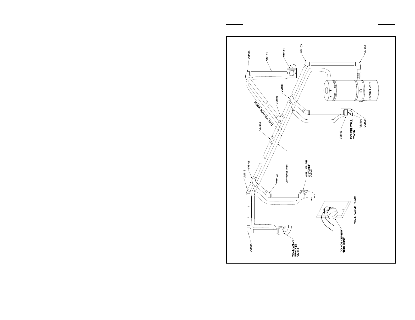
TYPICAL VACUUM SYSTEM INSTALLATION
2 of 17
3 of 17
Page 3
POWER UNIT INSTALLATION
ILLUSTRATION ABOVE SHOWS A TYPICAL AIR VAC UNIT
POWER UNIT INSTALLATION
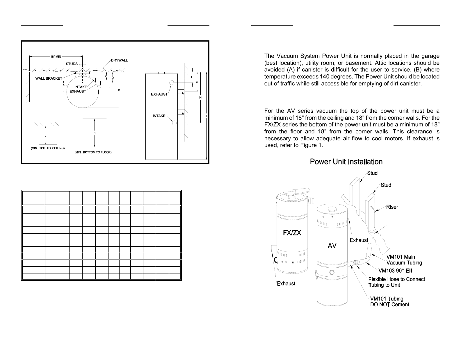
1.0 POWER UNIT LOCATION AND CONNECTION
The Vacuum System Power Unit is normally placed in the garage
(best location), utility room, or basement. Attic locations should be
avoided (A) if canister is difficult for the user to service, (B) where
temperature exceeds 140 degrees. The Power Unit should be located
out of traffic while still accessible for emptying of dirt canister.
2.0 POWER UNIT MOUNTING
For the AV series vacuum the top of the power unit must be a
minimum of 18" from the ceiling and 18" from the corner walls. For the
FX/ZX series the bottom of the power unit must be a minimum of 18"
from the floor and 18" from the corner walls. This clearance is
necessary to allow adequate air flow to cool motors. If exhaust is
used, refer to Figure 1.
Model Exhaust
Side
AV2500 R 14 16 2.8 4 8 23 24 38 18
AV3500 R 14 16 2.8 4 8 23 24 38 18
AV4500 R 14 16 2.8 4 8 23 24 38 18
AV5500 R 14 16 2.8 4 8 23 24 38 18
FX2000 L 14 16 8.9 4 7 4 28 30 18
FX3000 L 14 16 8.9 4 7 4 28 30 18
FX900 L 14168.94 7 4 283018
ZX5800 L 14 16 8.9 4 7 4 28 31 18
ZX6000 L 14 16 8.9 4 7 4 28 31 18
ZX7000 L 14 16 8.9 4 7 4 28 31 18
ZX8000 L 14 16 8.9 4 7 4 28 31 18
ABCDFG
H
IJ
Note: Dimensions above are in inches
4 of 17
Figure 1
5 of 17
Page 4

CAUTION:
A) The exhaust tubing must run outside the house, NOT INTO THE
ATTIC.
B) DO NOT exceed 30 ft. of exhaust tubing, in order to avoid motor failure
resulting from excessive back pressure.
C) DO NOT turn the exhaust piping, run within 18" of the power unit.
NOTE: After a proper location has been chosen for the power unit refer to
Figure 2 for securing the unit mounting bracket to the wall studs.
Steel tubing is also available and may be required by local building
codes.
120VAC 240VAC
NEMA 5-15R NEMA 6-15R
Figure 3 Figure 4
3.0 POWER UNIT ELECTRICAL REQUIREMENTS
The electrical requirements for the power units and maximum tubing
from power unit to farthest valve are as follows:
Figure 2
6 of 17
Model
Number
AV2500 120 11 15A 3 150
AV3500 120 12 20A 3 200
AV4500 120 13 20A 3 350
AV5500 240 7 20A 4 500
FX2000 120 11 15A 3 150
FX3000 120 12 20A 3 200
FX900 240 13 20A 4 500
ZX5800 120 11 15A 3 150
ZX6000 120 12 20A 3 200
ZX7000 120 13 20A 3 350
ZX8000 240 7 20A 4 500
Voltage
(Vac)
Current
(Amps)
Circuit
Breaker
Receptacle
See Fig Type
Maximum
Tubing
CAUTION: All circuit breakers must be SEPARATE and DEDICATED
as with any other major appliance. The electrical outlets
MUST match the plug WITHOUT THE USE OF ADAPTERS.
7 of 17
Page 5

4.0 WALL INLET VALVES
Locate the first inlet valve at a
point the farthest distance (see
Figure 6) from the Power Unit.
From this location, select
additional valve locations that
can be reached in all room
corners with a 30' hose.
Remember walls and furniture
can shorten the distance
serviced by a valve in some
areas, so be sure to locate
inlets with furniture and walls
in mind.
Figure 5
Alternate wall valve bracket
configurations are possible.
Nail a valve bracket (see Figure 5) to a wall stud 12" to 15" above the
floor, usually the same distance from the floor as electrical wall outlets.
Typical Wall Outlet Locations
Air Duct System Installation
Tee -Y
5.0 VACUUM DUCT SYSTEM
(Fig. 7)
90E EII
Tubing Strap
After the valve brackets are
nailed in place, drill a 2
Riser
9/16" diameter hole in the
header plate directly above
the valve bracket. Cement a
RISER tube (see Figure 5)
from the valve bracket,
Stud
Wall
Bracket
extending the tube through
the hole in the header plate
for each valve.
Starting from the farthest
inlet valve (Figure 6), lay
Wall EII Tee
Sole Plate
Figure 7
tubing (cut-to-length) on top
of ceiling joist and work toward the Power Unit. All Tee's and Tee-Y's
must curve in the direction of air flow. Connect all risers from inlet
valves to the main duct line using only Tee-Y's (Part VM106) or sweep
Ell's (Part VM103). Cement all duct connections at the time of
installation. There cannot be any air leaks in the duct systems. TEST
of vacuum integrity with wall inlet valves installed is highly
recommended. Vacuum leaks will affect system performance.
Ceiling
Joist
Fire
Break
Main Vacuum
Tube
Farthest Location
Figure 6
8 of 17
Hose Coverage
Note: The use of nail guards (VM118) are highly recommended.
Power Unit
6.0 ELECTRICAL WIRING (LOW VOLTAGE)
Low voltage #18 gauge, 2-conductor cable connects all inlet valves to
the Power Unit. Hose insertion in the wall valve inlet activates Power
Unit automatically; removing the hose stops the power Unit. Low
voltage cable follows the same route as the vacuum duct system.
Secure the wiring to the horizontal main line ducts with tape or VM450
quick clips, but DO NOT tape the cable to the risers. Secure the loose
cable end at each wall bracket, allowing 6" for the wall valve connection
and 18" at the Power Unit connection.
NOTE: Two 1/4" spade lugs are required to make this installation.
9 of 17
Page 6

CAUTION: All wiring installation must conform to local electrical codes.
Wiring in the ground (soil) must be in conduit. All wiring
installation must have a good, solid mechanical connection.
Protect all connections and/or splices against short circuits
using wire nuts or electrical tape.
7.0 TRIM OUT (INLET VALVES)
Do Not Cement inlet valves to the wall valve bracket. Valves require
replacement on occasion and if cemented to the duct system, they
cannot be removed or replaced.
8.0 VACUUM TUBING INSTALLATION EXISTING for CONSTRUCTION
8.1 Overhead Installation (Figure 8)
Two people are normally required to perform overhead installations.
Power Unit installation requirements are the same as in new
construction. Wall inlet valves should be limited to interior walls.
Exterior walls contain insulation and are not accessible from inside the
roof to drill holes for the vacuum duct. After marking each wall valve
location, check inside the roof area to see if a hole can be drilled in the
header tape for the tubing. Before drilling, check for electrical wiring. If
there are no obstructions, drill a hole in the header plate. It is possible
that you will hit a fire block about halfway down the wall. If this is the
case, you must use an extension drill and drill through the fire block.
Make sure your drill is straight up and down or you will come through
the side of the wall.
After holes are drilled, lower tubing from inside the roof to the wall
valve. Seldom is the roof high enough to use a single length of tubing.
As the tube is dropped down the wall to the valve location, several
short lengths of tubing should be cemented together with a coupling
(Part VM102).
At the valve location,
drill a 1" diameter hole
in the wall. Using a
flashlight from the attic,
check for hole
alignment. Then cut a
rectangular hole 2 ½"
horizontal and 3 ½"
vertically from the
center of the 1"
diameter hole. This hole
will allow an adapter
(Part VM107) to make
contact with tubing
inside the wall.
CEMENT THE
ADAPTER TO THE TUBING. Secure the adapter to the mounting
bracket (Part VM142) with screws. After the mounting bracket is
attached to the adapter, the completed assembly inside the wall is
ready for the inlet valve (Part VM195). DO NOT CEMENT THE INLET
VALVE. Tighten the valve against the wall with screws to the mounting
bracket.
8.2 Under The Floor Installation
(Figure 9)
In homes with a pier and beam
foundation or basement, either
the overhead or an under the
floor installation can be made.
Sometimes under the floor
installation is easier in an existing
home, especially if the roof has a
low pitch and clearances in the
attic adds to the installation
problem. Under the floor
installation also eliminates the
risk of fire blocks in the wall.
Shorter risers are also utilized,
eliminating the longer tube drop
from the attic. Vacuum tubing
should be secured to floor joist
with perforated nailing strips or tube straps.
Figure 8
Figure 9
10 of 17
11 of 17
Page 7

9.0 ALTERNATE INSTALLATION
An effective technique highly suitable for many types of construction
with adequate working room inside the roof is to make drops to the wall
inlet valves through the ceiling, passing the tube "through the wall" for
the inlet valve on the opposite side. If this method is used, the drop
from the inside of the roof is made in the corners of closets, utility
rooms, etc. where tubing is not visible or objectionable. On occasion
this might be the only alternative to placing an inlet valve in a desired
location.
TROUBLESHOOTING
IF THE MOTOR FAILS TO OPERATE
1. Push breaker reset button on power units.
2. Check panel circuit breaker that connects the central unit.
AFTER CHANGING OF THE BAG FOR THE ZX MODEL SERIES
After the bag has been changed and the light is still blinking, to “reset”
the circuit, push down on the rocker switch below the light and release.
SHOULD YOU LOSE VACUUM POWER
1. Check that all wall valves are closed.
2. Check that all gaskets on wall valves are sealed.
3. Check to see if dirt canister or bag needs emptying.
4. Check for obstructions in the hose, tools, or vacuum lines.
5. Check for any ruptures or breaks in the vacuum duct system.
If you are unable to resolve the operational problems, please contact
M&S Systems technical support at (800) 366-9422.
VACUUM SYSTEM SPARE PARTS
Spares may be purchased for field
repairs of vacuum power units.
FX Models
Part Number & Description FX900 FX3000 FX2000
440003 Switch, On/Off X X X
510967 Latch X X X
561558-2 Hanger Bracket X X X
563274 Circuit Breaker, 15AMP X X
730274-2 PCB, Electric Control Board X X
780382-2 Assembly, Motor X
780405-2 Assembly, Motor X
780468-2 Assembly, Motor X
780478 Module, Assy Transformer X
785001 Filter, Grey Flocked 10x10 X
785001-2 Filter, Grey Flocked 2.75x2.75 X X
785395-1 Assembly, Bag X X X
785453-2 Lid/Manifold Assembly X X X
787064-4 Lid X X
787066-2 Twin Lid X
AV Models
Part Number & Description AV2500 AV3500 AV4500 AV5500
101859 Gasket, Dust Receptacle XXXX
112996-3 Bag, Cloth, Filter XXXX
440003 Switch, On/Off XXXX
510967 Latch XXXX
561558-2 Hanger Bracket XXXX
561609 Assembly, Dirt Cannister XXXX
563273 Circuit Breaker, 10AMP X
563274 Circuit Breaker, 15AMP X X
563275 Circuit Breaker, 18AMP X
730274-1 PCB, Electric Control Board, 240V X
730274-2 PCB, Electric Control Board, 120V X X X
12 of 17
13 of 17
Page 8

Part Number & Description AV2500 AV3500 AV4500 AV5500
780382-2 Assembly, Motor X
780468-2 Assembly, Motor X
780469-2 Assembly, Motor X
780485 Assembly, Motor X
785001-2 Filter, Grey Flocked 3.5x3.5 XXXX
787064-4 Lid XXXX
VACUUM SYSTEM SPARE PARTS CONT.
ZX Models
Part Number # & Description ZX5800 ZX6000 ZX7000 ZX8000
440003 Switch, On/Off XXXX
460064 Switch, Reset Off/MOM XXXX
510967 Latch XXXX
561558-2 Hanger Bracket XXXX
730275-1 PCB Electronic Control Board, 240V X
730275-2 PCB Electronic Control Board, 120V X X X
780382-2 Assembly, Motor X
780468-2 Assembly, Motor X
780469-2 Assembly, Motor X
780485 Assembly, Motor X
785001-2 Filter, Grey Flocked 3.5x3.5 XXXX
785395-1 Assembly, Bag XXXX
785453-2 Lid/Manifold Assembly XXXX
787476 Lid XXXX
14 of 17
15 of 17
Page 9

M&S Systems Limited (2 or 10) Year
No-Fault Limited Warranty
M&S SYSTEMS Limited 2-Year No-Fault Product Warranty
M&S SYSTEMS warrants for 2 years all products to be free of defects (M&S SYSTEMS honors the 10-Year
No-Fault warranty for AirVac Gold power units. See section below). The warranty period begins from either
(1) the date of “first user” purchase of this product or (2) the first close of escrow date on a residence in which
this new product was originally installed. This warranty extends to the original user of the product and to each
subsequent owner of the product during the term of this warranty. M&S SYSTEMS will repair or replace, at
its option, parts and materials at no charge. Parts supplied under this warranty may be new or rebuilt at the
option of M&S SYSTEMS.
If, during the limited warranty period, it appears as though this product contains a defect which is covered by
this limited warranty, call our toll free service number before dismantling the product (1-800-877-6631).
Remember to attain a Return Authorization Number (RAN) before returning any product to M&S SYSTEMS.
Send this product freight pre-paid and insured to our service center for warranty repair. You will be advised
on shipping instructions when you call the toll free service number. M&S SYSTEMS will return the repaired
product freight pre-paid within the U.S.A. The installing dealer or distributor may assist you, at your choice
and expense, with returning product for repair. Please include a brief description of the problem and a dated
proof-of-purchase receipt with any product that is return ed for warranty repair. ANY PRODUCT RETURNED
WITHOUT A RETURN AUTHORIZATION NUMBER WILL BE REFUSED.
THIS LIMITED WARRANTY IS IN LIEU OF ANY OTHER WARRANTIES, EXPRESS OR IMPLIED,
INCLUDING ANY IMPLIED WARRANTY OF MERCHANTABILITY OR FITNESS FOR A
PARTICULAR PURPOSE OR OTHERWISE, AND OF ANY OTHER OBLIGATIONS OR LIABILITY ON
THE SELLER’S PART. THIS LIMITED WARRANTY DOES NOT COVER DAMAGE CAUSED BY
IMPROPER INSTALLATION, THE VIOLATION OF APPLICABLE BUILDING OR ELECTRICAL
CODES, OR THE USE OF NON-M&S/NON-AIRVAC WIRE, CABLE OR WALL HOUSINGS. THIS
LIMITED WARRANTY APPLIES ONLY TO PRODUCTS INSTALLED IN A PRIVATE RESIDENCE.
UNDER NO CIRCUMSTANCES SHALL THE SELLER BE LIABLE FOR CONSEQUENTIAL,
INCIDENTAL OR SPECIAL DAMAGES ARISING IN CONNECTION WITH USE, OR INABILITY TO
USE THIS PRODUCT. IN NO EVENT SHALL SELLER’S LIABILITY, FOR BREACH OF WARRANTY,
BREACH OF CONTRACT, NEGLIGENCE, OR STRICT LIABILITY, EXCEED THE COST OF THE
PRODUCT COVERED HEREBY. NO PERSON IS AUTHORIZED TO ASSUME FOR US ANY OTHER
LIABILITY IN CONNECTION WITH THE SALE OF THIS PRODUCT.
Some states do not allow the exclusion or limitation of consequential, incidental or special damages,
so the above limitation or exclusion may not apply to you. This limited warranty gives you specific
legal rights, and you may also have other rights which vary from state to state.
M&S SYSTEMS Limited 10-Year No-Fault Product Warranty for AirVac Gold Power Units
M&S SYSTEMS honors the 10-Year No-Fault Warranty applied to the AirVac Gold power unit as of
January 1, 2000. This warranty is identical to the M&S SYSTEMS 2-Year No-Fault Warranty, with the
exception that this warranty covers the AirVac Gold power unit for 10 years instead of 2. The M&S
SYSTEMS 10-Year No-Fault Warranty, applies ONLY to the AirVac Gold power unit, and no other M&S
SYSTEMS, M&S or AirVac product.
16 of 17
115465-4 Rev M
115465-4
17 of 17
 Loading...