

Page 1
2GIG-STVGRL1-345
STOVE & GRILL GUARD
INSTALLATION INSTRUCTIONS
The 2GIG® Stove & Grill Guard is a contact ON/OFF sensor that
alerts your security panel (and op onally the smartphone with
Alarm.com) when the knob on a stove/grill is turned ON. It is
compa ble with 2GIG security panels, including GC2, GC3, and
Vario. The Stove & Grill Guard is also compa ble with select
Honeywell Vista panels.
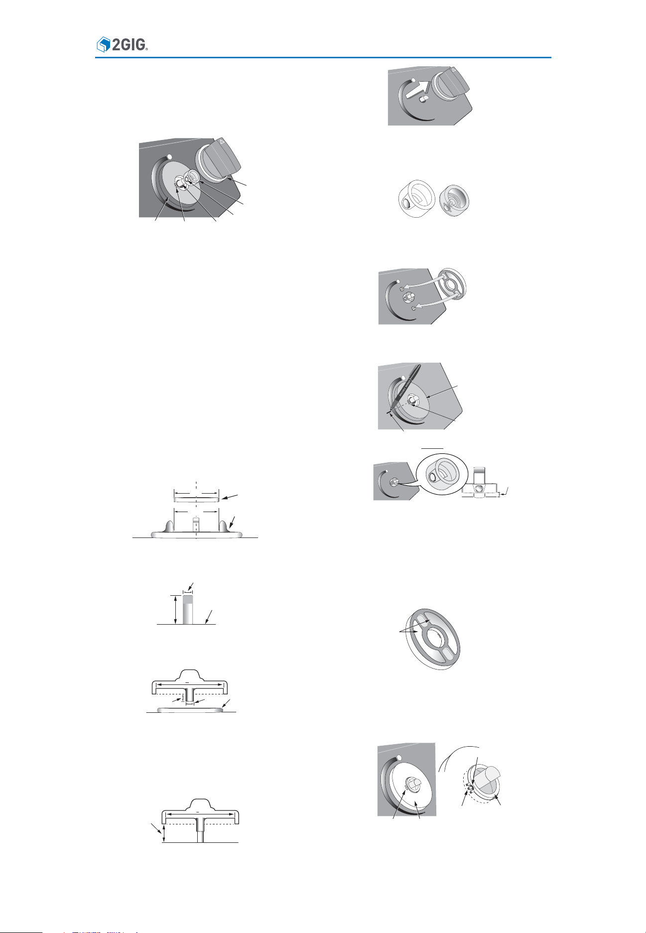
STOVE\GRILL
KNOB
SLEEVE
SENSOR DISC
INNER MARKS
Contents
Verify the package contains the following:
• One (1) sensor disc - with adhesive strips a ached
• Sleeves with magnets – 2 diff erent sizes
Pre-Installation Checks
Perform the following checks to determine whether or not the
product will be a good fi t with your stove/grill:
1. Ensure the stove/grill faceplate surface around the knob is
fl at. If screws are present around the knob stem, ensure the
following:
• The screw head diameter is less than 0.4 inches
• The screw head thickness is less than 0.12 inches
• The sensor disc fi ts over screws and is concentric with the
stem
2. Ensure the hole on the faceplate around the stem is not large
enough for the sleeve to fi t through and go underneath the
faceplate. If possible, use a fi xture (e.g., a rubber grommet,
with adhesives, if needed) that grips ghtly to the stem for
preven ng the sleeve from going underneath the faceplate.
3. If a trim ring (or fl ange) is around the knob, ensure the
• Inner diameter of the ring/fl ange is no smaller than 2.2
inches
• Surface inside the ring is fl at
2.2”
KNOB STEM
MAGNET
SENSOR DISC
3. Ensure the stove/grill surface around the knob area is clean.
4. Iden fy the sleeve that best fi ts your knob stem, from the two
provided. The larger sleeve is for the Weber Genesis series
grills. The addi onal sleeve is for other grills and stoves.
DO NOT PEEL THE PROTECTIVE BACKING MATERIAL FROM THE
5.
ADHESIVE STRIP ON THE SENSOR DISC. Place the sensor disc
on the knob stem area, and determine the ideal orienta on of
the disc (which may be infl uenced by the presence of screws).
Take note of the orienta on of the inner marks on the sensor
(e.g., 12-o'clock with respect to stem), and put a temporary
mark on the faceplate to indicate the orienta on.
SENSOR DISC
INNER MARKS
TEMPORARY MARK
6. Remove the sensor disc before installing the sleeve.
“.10”
>2.2”
TRIM RING/FLANGE
4. Ensure the stem's maximum diameter of the cross sec on is
between 0.25 - 0.38 inches and its length from the faceplate
surface upwards is at least 0.4 inches.
0.25-0.38”
FACEPLATE
>0.4”
SURFACE
5. If the knob post protrudes outside the bo om of the knob,
ensure its thickness is less than 0.4 inches and does not
protrude more than 0.1 inches outside of bo om of the knob.
If <2.2”
<
0.1”
SENSOR
DISC
<
0.4”
6. If the inside diameter of the knob is 2.2 inches or less, posi on
the knob on the knob stem such that the bo om of the knob
sits 0.35 inches above the faceplate. Check whether the knob
has enough engagement with the stem to stay stable and
fi rmly installed. This helps determine if there is enough space
to push the knob down and turn the stove/grill ON or OFF a er
the Stove & Grill Guard is installed.
Check for stability.
At least
0.35”
If <2.2”
Installation
1. Ensure the device (stove, grill, heater, etc.) is turned OFF. If
possible, also turn OFF the gas valve and/or the power source.
2. Remove the knob from the stove/grill.
7. Install the sleeve onto the knob stem with the cavity side
facing towards the faceplate. Ensure the marks on the sleeve
(which indicate the loca on of the magnet) align with the mark
on the faceplate from the previous step. Be careful to posi on
the bo om of the sleeve 0.10 inches above the faceplate of
the stove/grill. (The sleeve must not be in contact with the
faceplate during normal opera on.)
Note: For the Weber Genesis grill, there is only one orienta on
for installing the larger sleeve on the stem. Install the sleeve with
cavity facing outward un l fi rmly seated on the stem.
the
ADHESIVE
STRIPS
8. Remove the protec ve backing material from each adhesive
strip on the sensor disc.
9. Align the inner marks on the sensor disc with the magnet
on the sleeve. ENSURE THE SLEEVE IS CENTERED INSIDE
THE HOLE OF THE SENSOR DISC, WITH THE TWO PARTS NOT
TOUCHING EACH OTHER. Mount the sensor disc to the stove/
grill face.
MAGNET
INNER MARKS SENSOR DISC
INNER
MARKS
SLEEVE
10. Install the grill knob back onto the knob stem. If the inner
diameter of the knob is not bigger than the sensor disc, DO
NOT PUSH THE KNOB all the way in. It is important to leave
a 0.10-inch gap between the sensor disc and the bo om of
the knob. The gap allows the knob to freely turn ON and OFF
following installa on.
11. Use your panel to program the Stove & Grill Guard.
1 Copyright © 2018 Nortek Security & Control LLC
Page 2
Programming the Device on the GC2/GC3 Panel
For GC2 and GC3 panels, program the Stove & Grill Guard on your
2GIG panel with the following parameters. (Please refer to your
panel’s quick programming guide for the actual steps.)
Sensor Type: (23) No Response Type
Sensor Equipment Type: Contact
Equipment Code: (0862) 2GIG Thin Door/Window Contact
Serial Number: [Input the unique 7-digit TXID.]
2
1
Equipment Age: New
Sensor Loop Number: 2
Dialer/Transmission Delay: Enabled
Voice Descriptor: GAS LEFT ON
3
Sensor Reports: Enabled
Sensor Supervised: Disabled
Sensor Chime: [User-specifi ed]
1
This is a provisional Equipment Code. A new category called
“Stove & Grill Guard” (or similar name) will be added in a future
GC2/GC3 panel update.
2
Alterna vely, a Stove & Grill Guard can be automa cally learned in.
3
This is a recommended voice descriptor. The user may defi ne a
custom voice descriptor, as needed.
Programming the Device on the Vario Panel
For the Vario panel, a er learning in1 the Stove & Grill Guard, please
confi gure the zone the Stove & Grill Guard is in with the following
parameters:
Zone Type: Output Trigger
Zone Sound Armed Away:
Silent
Zone Sound Armed Stay: Silent
Zone Sound Disarmed: Chime or Silent
1
Alterna vely, you can use the Vario TXID to manually enroll the
device.
Programming the Device on the Honeywell Vista Panel
For the Honeywell Vista panel, fi rst enroll the Stove & Grill Guard
into the panel as follows:
• For Panel 15P, 20P or 50P, auto-enroll the device into the panel.
The LED will fl ash 6 mes to confi rm the enrollment.
• For Panel 10SE or 20SE, set the address to "00", then auto-enroll.
The LED will be solid green to confi rm the enrollment.
Then program the panel as follows:
1. Enter [4-digit installer code], then [800], then [*56]. When the
screen displays "Set to Confi rm?" press [*] bu on.
2. When prompted by the screen to "Enter ZN Num" input a
chosen zone number (ZN) between 09 and 48, then press [*]
bu on.
3. Type in the ZN to display the current zone summary on the
screen.
4. Enter the following parameters:
• ZT (zone type): [10]
• P (par on): [1]
• RC (report code): [01] then [0010]
• IN (input device type): [RF Trans. 3]
• Transmi er Serial Number: [A] then [7-digit TXID]
• Loop Number: [2]
5. Confi rm the zone summary displays the parameters correctly.
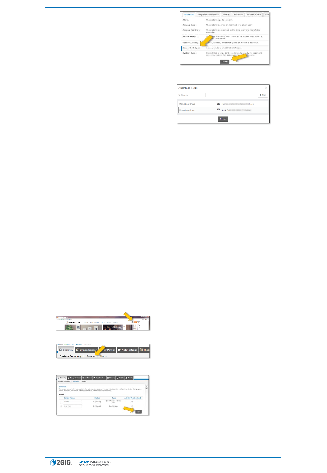
Setting up E-mail Notification
1. Navigate to hƩ p://www.alarm.com and click LOGIN.
2. Your systems dashboard page will appear. Select the Security tab
and click Sensors.
3. Iden fy the new sensor you added. You can rename the
Sensor Name. When fi nished, click Save.
–
Alarm.com Accounts Only
5. Click Sensor LeŌ Open. Add parameters. Also, click +Add
Recipient to add recipients associated with the no fi ca on.
6. Click Close when names have been selected, then click Save
NoƟ fi caƟ on.
Specifi cations
• Signal Range: 100 . open-air from a 2GIG panel
• Transmission Frequency: 345 MHz
• Disc dimensions: 2.2” diameter, 0.21” thickness
• Opera ng Temperature: 14°F to 167°F (-10°C to 75°C)
• Ba ery Life: Up to 5 years
FCC & IC Notice
This device complies with Part 15 of the FCC Rules and Industry Canada license
exempt standard(s). Opera on is subject to the following two condi ons:
(1) This device may not cause harmful interference, and
(2) This device must accept any interference received, including interference
received that may cause undesired opera on.
Le présent appareil est conforme aux CNR d’Industrie Canada applicables
aux appareils radio exempts de licence. L’exploita on est autorisée aux deux
condi ons suivantes:
(1) l’appareil ne doit pas produire de brouillage, et
(2) l’u lisateur de l’appareil doit accepter tout brouillage radioélectrique subi,
même si le brouillage est suscep ble d’en comprome re le fonc onnement.
This Class B digital apparatus complies with Canadian ICES-003.
Cet appareil numérique de la classe B est conforme à la norme NMB-003 du
Canada.
This equipment has been tested and found to comply with the limits for a Class
B digital device, pursuant to Part 15 of the FCC Rules. These limits are designed
to provide reasonable protec on against harmful interference in a residen al
installa on.
This equipment generates, uses, and can radiate radio frequency energy and, if
not installed and used in accordance with the instruc ons may cause harmful
interference to radio communica ons. However, there is no guarantee that
interference will not occur in a par cular installa on. If this equipment does
cause harmful interference to radio or television recep on, which can be
determined by turning the equipment off and on, the user is encouraged to try
to correct the interference by one or more of the following measures:
• Reorient or relocate the receiving antenna
• Increase the separa on between the equipment and receiver
• Connect the equipment into an outlet on a circuit diff erent from that to
which the receiver is connected
• Consult the dealer or an experienced radio/TV technician to help
WARNINGS:
• Changes or modifi ca ons not expressly approved by the manufacturer could
void the user’s authority to operate the equipment.
• The Stove & Grill Guard is not intended as a life-safety device. It is not
intended to replace any other safety considera ons.
Limited Warranty
This Nortek Security & Control product is warranted against defects in material
and workmanship for 12 months. Nortek Security & Control does not warrant
this product to consumers.
There are no obliga ons or liabili es on the part of Nortek Security & Control
for consequen al damages arising out of or in connec on with use or
performance of this product or other indirect damages with respect to loss of
property, revenue, or profi t, or cost of removal, installa on, or reinstalla on.
All implied warran es for func onality, are valid only un l the warranty expires.
This Nortek Security & Control LLC Warranty is in lieu of all other warran es
expressed or implied.
4. Click the NoƟ fi caƟ ons tab, and then +New NoƟ fi caƟ on
bu on to create a new event. The menu will appear with
the Standard tab open by default.
For technical support in the USA and Canada:
800.421.1587
Email: 2gigtechsupport@nortek.com
Visit www.nortekcontrol.com for technical support hours of opera on
For technical support outside of the USA and Canada:
Contact your regional distributor
Visit dealer.2gig.com for a list of distributors in your region
Patent Pending.
2GIG® is a registered trademark of Nortek Security & Control LLC.
2 Copyright © 2018 Nortek Security & Control LLC
10017336A X2
 Loading...