

Page 1
2GIG-DW30-345
OUTDOOR WIRELESS CONTACT SENSOR MANUAL
Installation Instructions
The Outdoor Wireless Contact (2GIG-DW30-345) is designed for installation on gates, doors, and other items that open and close.
It communicates with the control panel using the 345
MHz frequency. When the magnet (which is mounted
near the sensor) moves away from or closer to the
door contact’s sensor, signals are transmitted to the
control panel. The sensor also has an external input
that accepts connections from Normally Closed (NC)
dry contact devices. For added protection, it is also
equipped with a cover and wall tamper.
Box Contents
• Outdoor Sensor
• Magnet
• Lithium AA Batteries (2x)
• Mounting screws
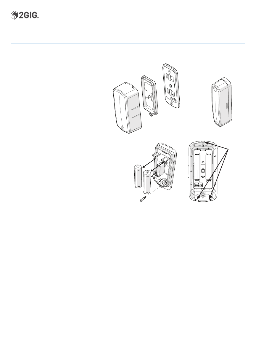
Installing the Batteries
1. Loosen the cover screw.
2. Choose any pry point, then use a small screwdriver to
remove the Sensor Mounting Plate
3. Remove the Sealing Cover.
4. Install the two Lithium Ion batteries.
5. Align the Sealing Cover to the screw hole in the sensor cover,
then press to close.
6. Engage Sensor tabs into mating holes in Sensor Mounting
Plate and swing closed. Secure with cover screw.
SENSOR
SEALING
COVER
Mounting Guidelines
Mount the Sensor within 100 ft (30 m) of the control panel. Although the transmitter may have a range of 350 ft (106.7 m) open
air, the sensor location can have a significant effect on range. In open / unobstructed situations, the transmitter range may be
greater. In adverse wireless conditions, changing the sensor orientation may lead to improved range.
Testing the Outdoor Wireless Contact
Before mounting the Outdoor Wireless Contact at the desired location, perform a walk test to verify that it can establish good
Radio Frequency (RF) communication with the control panel.
Utilize a Repeater (P/N: 2GIG-RPTR1-345) if the RF communication is insufficient for the desired location.
NOTE: To fully test the Outdoor Wireless Contact, see the control panel’s Installation and Programming Guide.
• Mount the device on a vertical surface (at a sufficient height) where water, snow and ice buildup won’t interrupt operation.
NOTE: Adding silicone caulk surrounding the rubber wire seal on the Sealing Cover will increase protection against water.
• Mount the Magnet on the magnet sensing side of the Sensor. On wooden surfaces a gap of approximately 2” is possible.
This will be decreased when mounting on metal surfaces.
• Mount the Sensor on the stationary surface, and mount the Magnet on the moving surface.
• Mount the Magnet and Sensor parallel with one another.
• If installed on a wooden surface, mount the sensor and magnet on the inside of the structure (if possible).
NOTE: Use screws suitable for the mounting surface.
• If mounted on a curved surface, use zip ties and/or suitable screws to fasten the Sensor and Magnet.
Tamper Protection:
The tamper switch will activate if the cover is removed or if the sensor is detached from its mounting location.
SENSOR
MOUNTING
PLATE
MAGNET
Pry points
1 Copyright © 2018 Nortek Security & Control LLC
Page 2
Outdoor Wireless Contact | Installation Instructions
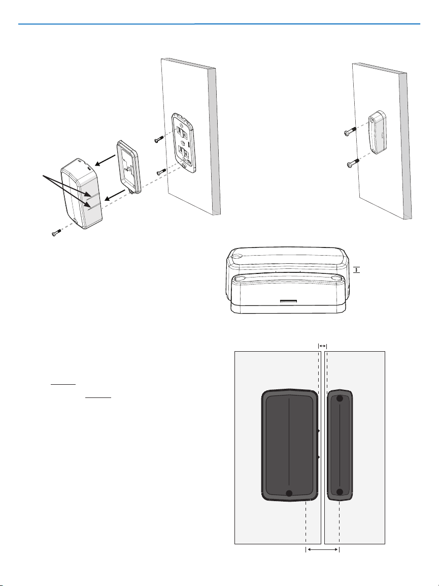
Mounting the Sensor on a Flat Surface.
1. Loosen the cover screw and remove the
Sensor Mounting Plate.
2. Ensure that the Magnet Direction Marks
are aligned toward the desired magnet
location.
3. Screw the Mounting plate into the
desired surface.
4. Replace the Sensor onto the Mounting
plate and tighten the cover screw.
5. Secure the magnet into place.
Magnet
direction
marks
Sensor and Magnet Mounting Height
Ideally, the Sensor and Magnet should be mounted on
surfaces of equal height.
When mounted at a level height, the 1/4” preferred mounting
height offset should be attained.
A height offset that exceeds 1/4” may decrease detection
capabilities.
Mounting the Magnet on a Flat Surface.
1. Ensure that the magnet marks are aligned
to the desired magnet location.
2. Mount the sensor into the desired
surface using the two screws.
Recommended Gap = 0.25"
1/4”
Recommended
Sensor and Magnet Mounting Distance
The preferred mounting distance between the Sensor and
Magnet is 1/4 inch.
The maximum gap is 2 inches.
2 Copyright © 2018 Nortek Security & Control LLC
Mounted Surface Mounted Surface
Maximum Gap = 2"
Page 3

Mounting on a Curved Surface
Strap ties and cable ties used for mounting are not supplied.
Recommended are:
• Self-locking stainless steel strap ties (recommended)
• Heavy duty Nylon 6/6 lN and Temperature Rated cable ties
(0.5 inch wide)
• A combination of screws and ties.
Figure 1: Example: SelfLocking Stainless Steel Strap
EXTERNAL WIRING - May be used with external closed contact switches.
Note: Use minimum of 22AWG jacketed
cable. The contact switch must be a Form
C (SPDT) type.
UL: Maximum wire length cannot exceed 3 feet.
1. Strip the cable jacket back about four
inches to provide adequate space for
Sealing Cover removal while changing
CLOSED (NC)
COMMON
OPEN (NO)
Connect Wires to the Terminal Block
batteries.
2. Feed the cable through the access hole
in Sensor Mounting Plate. Use the cable
notch on mounting plate to pass through
the jacketed portion of cable, then attach
the Sensor Mounting Plate.
3. Route the cable to the external contact
switch and fasten at intervals to secure
the cable.
SEALING COVER
A
d
d
4. Remove the Sealing Cover and feed the
wires through the rubber wire seal. If
installed, remove the batteries.
5. Connect the wires to terminal block in the
battery chamber, then install the batteries.
SENSOR
6. Replace the Sealing Cover.
Note: The cover screw hole should line up with the screw hole in the sensor cover. Press to close. Apply silicone caulking to
the rubber wire seal.
7. Engage the tabs in the Sensor Mounting Plate to the slots in the sensor, and swing closed. Secure with cover screw.
Cau
lki
CONNECT TO EXTERNAL
CONTACT SWITCH
SENSOR
MOUNTING PLATE
n
g
t
o
S
eal
i
n
g
C
o
v
e
r
PAINTING THE SENSOR
The sensor and magnet may be painted to match the color of the mounting surface. Only paints made for plastic may be used.
Follow the manufacturer's instructions for preparing the plastic, applying the paint and recommended drying times.
NOTE: DO NOT USE METALLIC PAINT COLORS.
3 Copyright © 2018 Nortek Security & Control LLC
Page 4

Specifications
Wireless Signal Range 350 ft (106.7 m) open air
with Wireless Control
Panel
Code Outputs Open, Restore,
Supervisory, Low
Battery, External Open,
External Restore,
Tamper, tamper Restore
Transmitter Frequency 345 MHz
Unique ID Codes Over one (1) million
different code
combinations
Supervision Interval 70 minutes.
External Input Accepts N/C dry contact
devices
Magnet Dimensions (L x W x H) 4.06 x 0.98 x 1.1” (103 x
25 x 28 mm)
Magnet Type Rare Earth
Magnet Gap Up to 2"
Sensor Dimensions (L x W x H) 4.57 x 2.13 x 1.54” (116 x
54 x 39 mm)
Housing Material ASA
Color Black
Operating Temperature -40ºF to 150 ºF (-40ºC
to 66 ºC)
Relative Humidity 0 ~ 100%
IP Rating Tested to IP56
Battery (Included) Two (2) Lithium AA
Certifications FCC, IC
REGULATORY INFORMATION
This equipment has been tested and found to comply with the limits for Class B Digital
Device, pursuant to Part 15 of the FCC Rules. These limits are designed to provide
reasonable protection against harmful interference in a residential installation. This
equipment generates and can radiate radio frequency energy and, if not installed and
used in accordance with the instructions, may cause harmful interference to radio
communications. However, there is no guarantee that interference will not occur in a
particular installation. If this equipment does cause harmful interference to radio or
television reception, which can be determined by turning the equipment off and on, the
user is encouraged to try to correct the interference by one or more of the following
measures.
Reorient or relocate the receiving antenna
Increase the separation between the equipment and receiver
Connect the equipment into an outlet on a circuit different from that to which the receiver
is connected
Consult the dealer or an experienced radio/TV technician for help.
Any changes or modications not expressly approved by the party responsible for
compliance could void the user’s authority to operate the equipment.
Le présent appareil est conforme aux CNR d’Industrie Canada applicables aux appareils
radio exempts de licence. Ľexploitation est autorisée aux deux conditions suivantes:
(1) ľappareil ne doit pas produire de brouillage, et (2) ľutilisateur de ľappareil doit
accepter tout brouillage radioélectrique subi, même si le brouillage est susceptible ďen
compromettre le fonctionnement.
FCC COMPLIANCE STATEMENT
This device complies with FCC Rules and Regulations as Part 15 devices as well as
Industry Canada license exempt RSS Rules and Regulations. Operation is subject to the
following two (2) conditions: This device may not cause harmful interference. This device
must accept any interference received, including interference that may cause undesired
operation.
INDUSTRY CANADA (IC) COMPLIANCE
This device complies with Industry Canada license-exempt RSS standard(s). Operation
is subject to the following two conditions: (1) this device may not cause interference,
and (2) this device must accept any interference, including interference that may cause
undesired operation of the device. Repairs to certied equipment should be made by
an authorized Canadian maintenance facility designated by the supplier. Any repairs or
alterations made by the user to this equipment, or equipment malfunctions, may give the
telecommunications company cause to request the user to disconnect the equipment.
Users should ensure for their own protection that the electrical ground connections of
the power utility, telephone lines and internal metallic water pipe system, if present,
are connected together. This precaution may be particularly important in rural areas.
Users should not attempt to make such connections themselves, but should contact the
appropriate electric inspection authority, or electrician, as appropriate.
LIMITED WARRANTY
This Nortek Security & Control LLC product is warranted against defects in material
and workmanship for two (2) years. This warranty extends only to wholesale customers
who buy direct from Nortek Security & Control LLC or through Nortek Security & Control
normal distribution channels. Nortek Security & Control does not warrant this product to
consumers. Consumers should inquire from their selling dealer as to the nature of the
dealer’s warranty, if any.
There are no obligations or liabilities on the part of Nortek Security & Control for
consequential damages arising out of or in connection with use or performance of this
product or other indirect damages with respect to loss of property, revenue, or prot, or
cost of removal, installation, or reinstallation. All implied warranties for functionality, are
valid only until the warranty expires. This Nortek Security & Control Warranty is in lieu of all
other warranties expressed or implied.
4 Copyright © 2018 Nortek Security & Control LLC
Nortek Security & Control LLC | 2GIG
5919 Sea Otter Place, Suite 100
Carlsbad, Ca. 92010
For technical support in the USA and Canada:
855‐2GIG‐TECH (855‐244‐4832)
Email: 2gigtechsupport@nortekcontrol.com
Visit www.nortekcontrol.com for technical support hours of operation
For technical support outside of the USA and Canada:
Contact your regional distributor
Visit www.dealer.2gig.com for a list of distributors in your region
10021755A
 Loading...