

Page 1
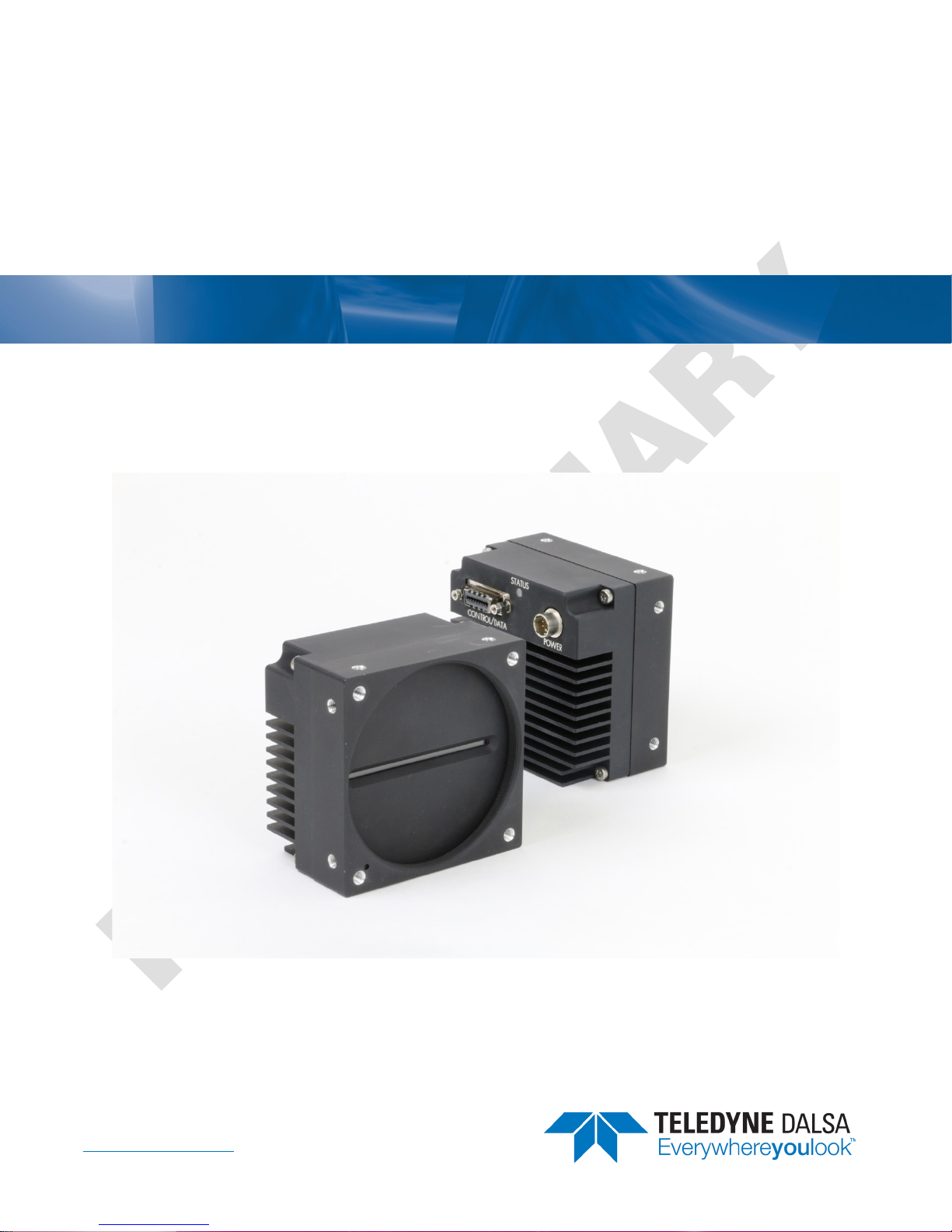
Linea Camera Link HS
Camera User’s Manual
16k Monochrome CMOS Line Scan
sensors |
cameras
| frame grabbers | processors | software | vision solutions
P/N: 03-032-20249-00
www.teledynedalsa.com
Page 2

Notice
© 2016 Teledyne DALSA
All information provided in this manual is believed to be accurate and reliable. No
responsibility is assumed by Teledyne DALSA for its use. Teledyne DALSA reserves the right
to make changes to this information without notice. Reproduction of this manual in whole or
in part, by any means, is prohibited without prior permission having been obtained from
Teledyne DALSA.
Microsoft and Windows are registered trademarks of Microsoft Corporation in the United
States and other countries. Windows, Windows 7, Windows 8 are trademarks of Microsoft
Corporation.
All other trademarks or intellectual property mentioned herein belong to their respective
owners.
Document Date: December 12, 2016
Document Number: 03-032-20249-00
Contact Teledyne DALSA
Teledyne DALSA is headquartered in Waterloo, Ontario, Canada. We have sales offices in
the USA, Europe and Asia, plus a worldwide network of representatives and agents to serve
you efficiently. Contact information for sales and support inquiries, plus links to maps and
directions to our offices, can be found here:
Sales Offices: http://www.teledynedalsa.com/corp/contact/offices/
Technical Support: http://www.teledynedalsa.com/imaging/support/
About Teledyne DALSA
Teledyne DALSA is an international high performance semiconductor and electronics
company that designs, develops, manufactures, and markets digital imaging products and
solutions, in addition to providing wafer foundry services.
Teledyne DALSA Digital Imaging offers the widest range of machine vision components in
the world. From industry-leading image sensors through powerful and sophisticated
cameras, frame grabbers, vision processors and software to easy-to-use vision appliances
and custom vision modules.
Page 3

Contents
LINEA CAMERA LINK HS SERIES OVERVIEW ................................................. 3
DESCRIPTION ................................................................................................ 3
Linea CLHS Application Advantages .......................................................... 4
Applications ........................................................................................... 4
PART NUMBERS AND SOFTWARE REQUIREMENTS ....................................................... 5
SUPPORTED INDUSTRY STANDARDS ....................................................................... 6
GenICam .............................................................................................. 6
Camera Link HS ..................................................................................... 6
CAMERA SPECIFICATIONS OVERVIEW ..................................................................... 7
Storage, Humidity and MTBF Specifications ............................................... 8
Compliance and EMI Certifications ............................................................ 8
Spectral ................................................................................................ 9
Responsivity .......................................................................................... 9
Effective Quantum Efficiency ................................................................. 10
CAMERA SETUP ........................................................................................... 11
SYSTEM PRECAUTIONS AND CLEANING ................................................................. 11
Precautions ......................................................................................... 11
Cleaning the Device .............................................................................. 11
Electrostatic Discharge and the Sensor ................................................... 11
CONNECTORS .............................................................................................. 12
Power Connector .................................................................................. 12
Data Cables ......................................................................................... 13
Establishing Camera Communications ..................................................... 13
Establishing Data Integrity .................................................................... 14
INSTALL & CONFIGURE FRAME GRABBER & SOFTWARE .............................................. 14
Using Sapera CamExpert ....................................................................... 14
CAMERA OPERATION ................................................................................... 16
CAMEXPERT FOR LINEA CLHS CAMERAS ............................................................... 16
CamExpert Panes ................................................................................. 16
Creating a Camera Configuration File in the Host...................................... 18
Factory Settings ................................................................................... 19
Open the CamExpert Panes ................................................................... 19
TYPICAL SETUP AND EVALUATION ....................................................................... 21
Optical Configuration ............................................................................ 21
Camera Timing & Control ...................................................................... 21
Acquiring an Image .............................................................................. 21
CHECK CAMERA AND SENSOR INFORMATION .......................................................... 22
Verify Temperature and Voltage ............................................................. 22
Pixel Format ........................................................................................ 23
INTERNAL TEST IMAGE GENERATOR ..................................................................... 24
CALIBRATING THE CAMERA ............................................................................... 25
Flat Field Parameters ............................................................................ 27
GAIN AND BLACK LEVEL (OFFSET) ...................................................................... 28
TRIGGER MODES .......................................................................................... 30
EXPOSURE CONTROLS .................................................................................... 31
Linea CLHS Series Camera Contents • 1
Page 4

BINNING .................................................................................................... 34
PIXEL READOUT DIRECTION (MIRRORING MODE) .................................................... 36
AREA OF INTEREST (AOI) SETUP ....................................................................... 36
SAVING AND RESTORING CAMERA SETTINGS .......................................................... 39
Camera Configuration Selection Dialog .................................................... 39
CAMERA FIRMWARE UPDATES ............................................................................ 40
DOWNLOAD A LIST OF CAMERA PARAMETERS .......................................................... 41
FILE ACCESS VIA THE CAMEXPERT TOOL ............................................................... 41
TECHNICAL SPECIFICATIONS ...................................................................... 43
MECHANICAL SPECIFICATIONS ........................................................................... 43
ADDITIONAL NOTES ON LINEA CLHS IDENTIFICATION AND MECHANICAL ......................... 44
EMC DECLARATIONS OF CONFORMITY ................................................................. 45
ADDITIONAL REFERENCE INFORMATION .................................................... 46
OPTICAL CONSIDERATIONS .............................................................................. 46
Illumination ......................................................................................... 46
Light Sources ....................................................................................... 46
Lens Modeling ...................................................................................... 47
Magnification and Resolution ................................................................. 47
SENSOR HANDLING INSTRUCTIONS ..................................................................... 48
Electrostatic Discharge and the Sensor ................................................... 48
Protecting Against Dust, Oil and Scratches .............................................. 48
Cleaning the Sensor Window ................................................................. 49
APPENDIX A: GENICAM COMMANDS ............................................................ 50
CAMERA INFORMATION CATEGORY ...................................................................... 50
Camera Information Feature Descriptions ................................................ 50
CAMERA CONTROL CATEGORY ........................................................................... 52
Camera Control Feature Descriptions ...................................................... 52
I/O CONTROL CATEGORY ................................................................................ 53
I/O Control Feature Descriptions ............................................................ 53
FLAT FIELD CATEGORY .................................................................................... 53
Flat Field Feature Descriptions ............................................................... 53
IMAGE FORMAT CONTROL CATEGORY ................................................................... 54
Image Format Control Feature Description .............................................. 54
TRANSPORT LAYER CATEGORY ........................................................................... 55
Transport Layer Feature Descriptions ...................................................... 55
DEVICE STREAMING REGISTERS ......................................................................... 57
Start – End Command Requirements ...................................................... 57
FILE ACCESS CONTROL CATEGORY ...................................................................... 57
File Access Control Feature Descriptions .................................................. 57
APPENDIX C: ERROR AND WARNING MESSAGES ......................................... 59
BIST: BUILT IN SELF TEST .............................................................................. 59
OPERATIONAL ERROR CODES ............................................................................ 60
DOCUMENT REVISION HISTORY .................................................................. 61
2 • Contents Linea CLHS Series Camera
Page 5
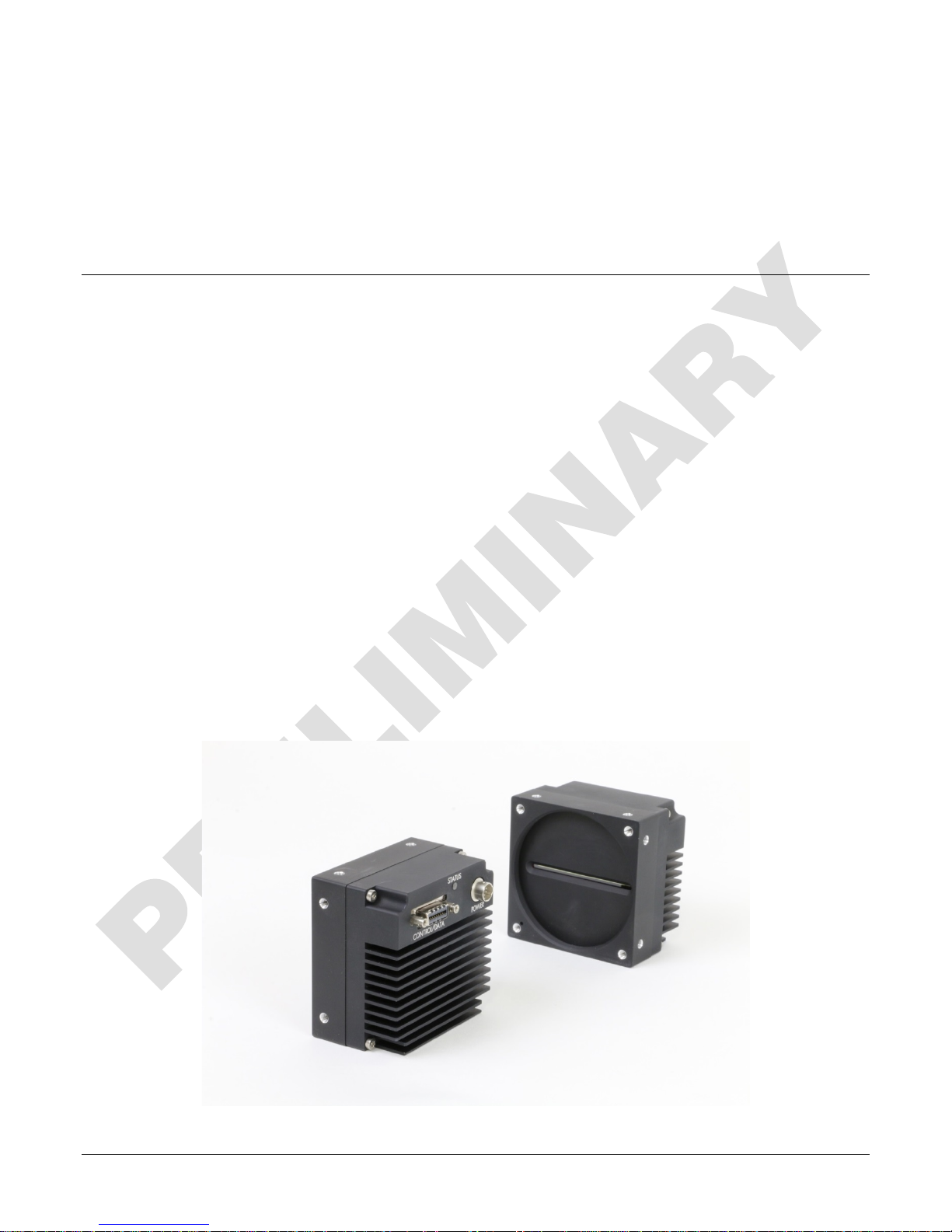
Linea Camera Link HS Series
Overview
Description
The new Linea™ line scan cameras deliver the exceptional performance and features found in
Teledyne DALSA’s current lineup of high-end cameras at an unprecedented price point.
Based on the most advanced CMOS line scan technology, the Linea Camera Link HS (CLHS)
cameras have a 16k single line 3.52 μm x 3.52 μm pixel array at a 71 kHz maximum line rate with
Camera Link HS output.
With excellent sensitivity and speed, Linea surpasses the requirements of demanding applications—
such as materials grading and inspection, transportation safety, and general purpose machine
vision.
The Linea lineup of cameras are compact, light-weight, robust and feature-rich—including flat-field
correction, multiple ROI and AOI, multiple user configuration sets, and calibration coefficients for
various lighting conditions.
The Linea CLHS camera is one of a new series of affordable and easy-to-use digital cameras
specifically engineered for industrial imaging applications requiring embedded image processing
and improved network integration.
These Linea cameras use industry standard Camera Link HS protocol to dependably capture and
transfer images from the camera to the host PC.
The GenICam compliant Linea is easy to set up and integrate using a GUI, such as Teledyne
DALSA’s Sapera camera configuration utility CamExpert.
Linea CLHS Series Camera Linea Camera Link HS Series Overview • 3
Page 6

Linea CLHS Application Advantages
• High speed: up to 71 kHz
• 16,384 pixel resolutions
• Compact and robust camera body
• Multiple regions of interest for calibration and data reduction
• 8 bit or 12 bit output
• Small flat field and lens shading correction
• 8 programmable coefficient sets
• GenICam compliant interfacing
Applications
• Automated optical inspection
• Security systems
• High performance sorting systems
• Materials grading and inspection systems
• Web inspection
• General purpose machine vision
4 • Linea Camera Link HS Series Overview Linea CLHS Series Camera
Page 7
Part Numbers and Software Requirements
This manual covers the Linea Camera Link HS models summarized below. New models area added
to this manual as they are released by Teledyne DALSA.
Camera Resolution Pixel size
Linea 16k CLHS 16384 x 1 3.52 µm x 3.52 µm 71 kHz M72 x 1 LA-HM-16K07A-00-R
Max. Line Rate Lens Mount
(threaded)
Accessories Order Number
M72 x 0.75 F, F-mount adapter 12 mm BFD lens, heavy duty AC-LN-00001-xx-R
For a list of accessories go to http://www.teledynedalsa.com/imaging/products/cameras/accessories/
Optical filters are available from http://www.midwestopticalsystems.com/
Teledyne DALSA Software Platform
Sapera LT version 7.50 or higher
includes CamExpert GUI application
Sapera provides everything needed to develop imaging
applications.
Camera Firmware Embedded within camera
GenICam support (XML camera description file) Embedded within camera
Sapera Processing Imaging Development Library
(available for Windows or Linux - sold separately)
Available for free download:
http://www.teledynedalsa.com/imaging/products/softw
are/sapera/lt/
Contact Teledyne DALSA Sales
Product Number
Third Party GenICam GenCP Software Requirements
Support of GenICam GenApi version 2.3 General acquisition and control. File access: firmware,
Support of GenICam XML schema version 1.1
GenICam support — XML camera description file Embedded within Linea CL
FFC, configuration data, upload & download.
Linea CLHS Series Camera Linea Camera Link HS Series Overview • 5
Page 8
RXC
TXC
TX1
TX2
TX3
TX4
TX5
TX6
TXC
RXC
RX1
RX2
RX3
RX4
RX5
RX6
Data Lane 6
Data Lane 0
Command
Channel
Video
Channel
Link
Camera
(C2,7M1)
Frame Grabber
(C2,7M1)
Supported Industry Standards
GenICam
The Linea CLHS camera is GenICam™ compliant and implements a superset of the GenICam
Standard Features Naming Convention specification V1.5.
This description takes the form of an XML device description file using the syntax defined by the
GenApi module of the GenICam specification. The camera uses the GenICam Generic Control
Protocol (GenCP V1.0) to communicate over the Camera Link HS command lane.
For more information see www.genicam.org
Camera Link HS
The Linea CLHS camera is Camera Link HS™ version 1.0 compliant. Camera Link HS is the next
generation of high performance communications standards and is used where a digital industrial
camera interfaces with single or multiple frame grabbers with data rates exceeding those
supported by Camera Link.
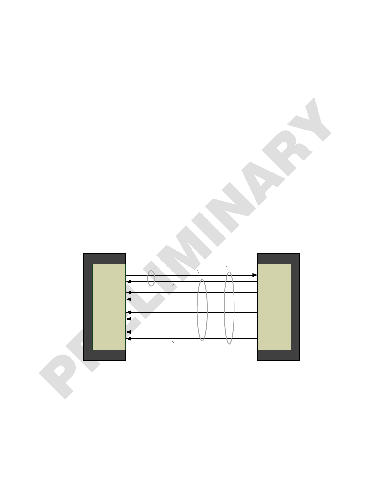
The Linea CLHS camera includes 2 Camera Link HS compatible connectors, each capable of
supporting data rates up to 2.1 gigabytes per second (GB/s). The connector can also interface with
standard ‘CX4 Active Optical Cable’ fiber modules where very long data transmission is required—
up to 300 meters.
.
Figure 1. Single CLHS Connector Configuration
The command channel is used by the frame grabber to send command, configuration, and
programming data to the camera and to receive command responses, status, and image data from
the camera.
The designation C2, 7M1 defines the use of a SFF-8470 connector (C2) and up to 4 lanes of data
with 1 command channel using M-Protocol (8b/10b) at the default speed of 3.125 GB/s.
An additional feature of CLHS is that the initialization of the frame grabber automatically starts a
discovery process that will identify the lane configuration of the camera. This process is transparent
to the user and requires no action by the user to correctly configure the link.
6 • Linea Camera Link HS Series Overview Linea CLHS Series Camera
Page 9
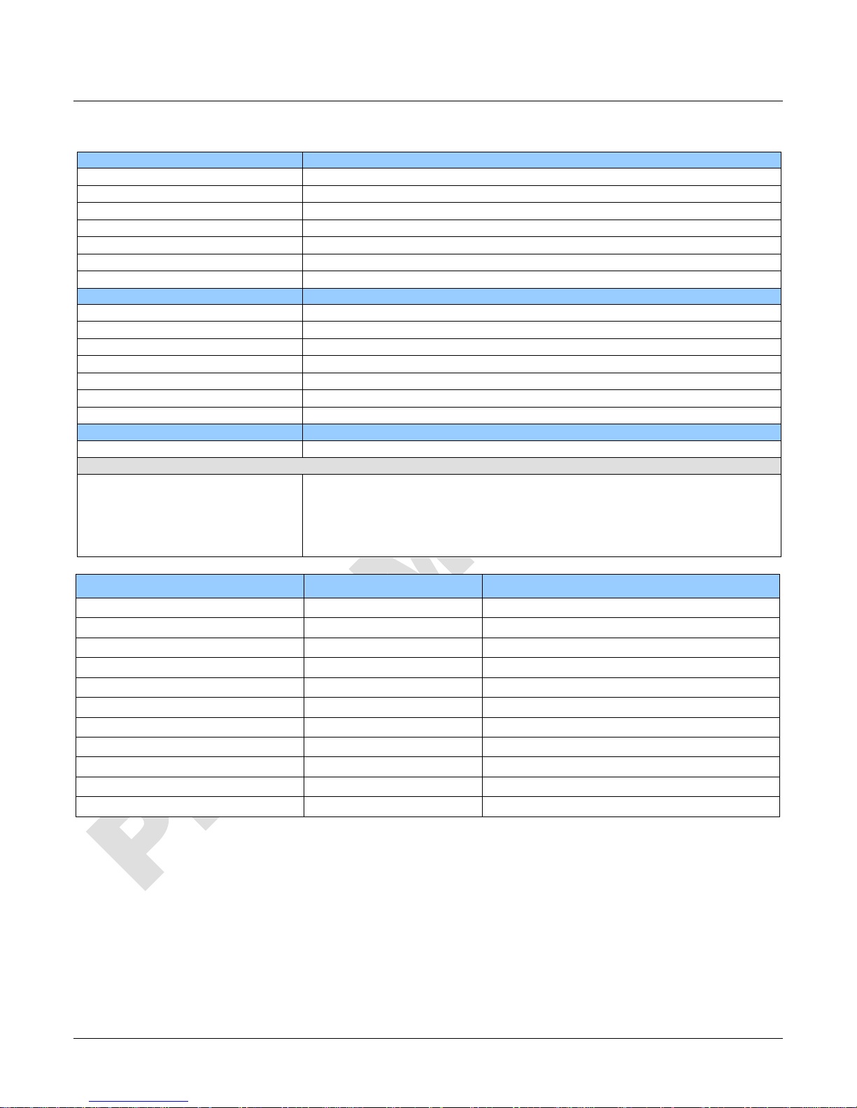
Imager Format
High speed CMOS line scan
Resolution
16, 384 pixels
Pixel Size
3.52 µm x 3.52 µm
Line Rate
71 kHz, maximum
Exposure Time
4 µs to 3 ms
Bit Depth
8 bit or 12 bit, selectable
Control & Data Interface
Camera Link HS
Power Connector
Hirose 6-pin male circular
Power
< 15 W
Size
76.0 mm (W) x 76.0 mm (H) x 52.86 mm (D)
Mass
< 360 g
Sensor to Camera Front Distance
12 mm
z
± 0.3°
Camera Specifications Overview
Specifications Performance
Pixel Fill Factor 100 %
Connectors and Mechanicals
Supply Voltage +12 V to + 24 V DC (+11.4 V to +25.2 V maximum limits)
Operating Temp 0 °C to +65 °C, front plate temperature
Optical Interface
Sensor Alignment (aligned to sides of camera)
Θ y (parallelism)
x
y
z
Θ
0.08° or 100 µm
± 300 µm
± 300 µm
± 300 µm
Operating Ranges Performance Notes
Dynamic Range > 60 dB
Random Noise < 3.06 DN* rms FFC enabled
Broadband Responsivity 80 DN / (nJ / cm2)
Gain Nominal range 1x to 10x
DC Offset 7 DN FFC enabled
PRNU < 1.5% @ 50% Sat
FPN < 5 DN
SEE 50 nJ / cm2
NEE 38.1 pJ / cm2
Antiblooming > 100 (x Saturation)
Integral non-linearity 1.5 % DN
*DN = digital number
Test Conditions:
• Values measured using 12-bit @ 1x gain.
• 10 kHz line rate.
• Light source: broadband, quartz halogen, 3250 K with 700 nm IR cut-off filter.
• Front plate temperature: 45º C.
Linea CLHS Series Camera Linea Camera Link HS Series Overview • 7
Page 10
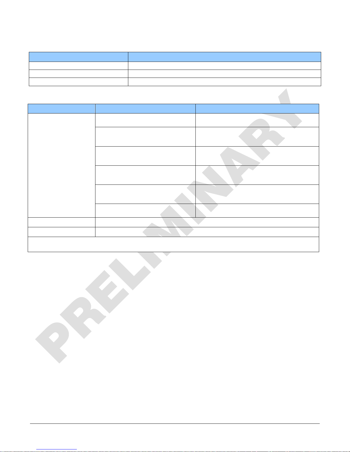
Storage, Humidity and MTBF Specifications
Environmental Specifications
Storage temperature range -20 °C to +80 °C
Humidity (storage and operation) 15% to 85% relative, non-condensing
MTBF (mean time between failures) >100, 000 hours, typical field operation
Compliance and EMI Certifications
Compliance Directives Standards ID Overview
EN55032 (2012) Electromagnetic compatibility of multimedia
EN55011 (2009) with A1(2010) Industrial, scientific and medical equipment —
EN 61326-1 (2013) Electrical equipment for measurement, control and
CE
FCC
RoHS
EN 55024 (2010) Information technology equipment —
CISPR 11 Industrial, scientific and medical equipment —
CISPR 32 Electromagnetic compatibility of multimedia
Part 15, class A
Compliancy as per European directive 2004/105/EC
For an image of the Linea CLHS certificate see the
EMC Declarations of Conformity section.
equipment — Emission requirements
Radio-frequency disturbance characteristics —
Limits and methods of measurement
laboratory use — EMC requirements —
Part 1: General requirements
Immunity characteristics —
Limits and methods of measurement
Radio-frequency disturbance characteristics —
Limits and methods of measurement
equipment - Emission requirements
8 • Linea Camera Link HS Series Overview Linea CLHS Series Camera
Page 11
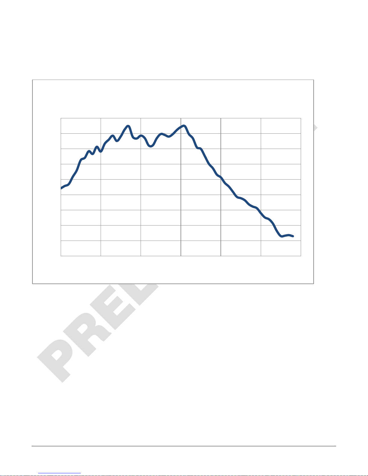
Spectral Responsivity
The responsivity graph describes the sensor’s response to different wavelengths of light (excluding
lens and light source characteristics).
Linea 16k Responsivity
(12 bit, 1x Gain)
90
80
70
60
50
40
30
Responsivity (DN/nJ/cm^2)
20
10
0
400 500 600 700 800 900 1000
Wavelength (nm)
Linea CLHS Series Camera Linea Camera Link HS Series Overview • 9
Page 12
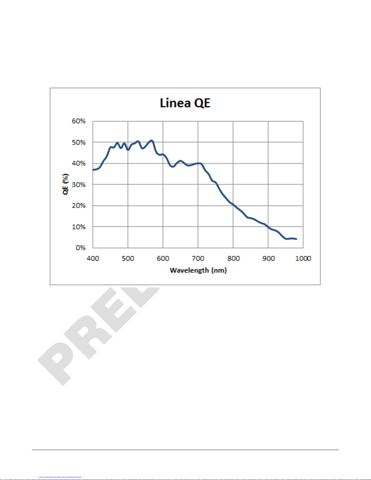
Effective Quantum Efficiency
The quantum efficiency graph describes the fraction of photons at each wavelength that contribute
charge to the pixel.
10 • Linea Camera Link HS Series Overview Linea CLHS Series Camera
Page 13
Camera Setup
System Precautions and Cleaning
Precautions
• Read these precautions and the rest of the information in this manual before using the
camera.
Do not open the housing of the camera. The warranty is voided if the housing is
opened.
• Confirm that the camera’s packaging is undamaged before opening it. If the packaging is
damaged please contact the related logistics personnel.
• Keep the camera’s front plate temperature in a range of 0 °C to +65 °C during operation.
• Do not operate the camera in the vicinity of strong electromagnetic fields. In addition, avoid
electrostatic charging, violent vibration, and excess moisture.
• Though this camera supports hot plugging, it is recommended that you power down and
disconnect power to the camera before you add or replace system components.
Cleaning the Device
To clean the device, avoid electrostatic charging by using a dry, clean absorbent cotton cloth
dampened with a small quantity of pure alcohol. Do not use methylated alcohol.
To clean the surface of the camera housing, use a soft, dry cloth. To remove severe stains use a
soft cloth dampened with a small quantity of neutral detergent and then wipe dry. Do not use
volatile solvents such as benzene and thinners, as they can damage the surface finish.
Electrostatic Discharge and the Sensor
Image sensors and the camera bodies housing are susceptible to damage from electrostatic
discharge (ESD). Electrostatic charge introduced to the sensor window surface can induce charge
buildup on the underside of the window. If this occurs, the charge normally dissipates within 24
hours and the sensor returns to normal operation.
Linea CLHS Series Camera Camera Setup • 11
Page 14

Power
A
Control & Data
B
Camera Link HS
Status
C
1
+12 V to +24 V DC
4
GND
2
+12 V to +24 V DC
5
GND
3
+12 V to +24 V DC
6
GND
C
B
A
Connectors
The camera has two connectors:
• A Hirose 6-pin connector for camera power.
• A CLHS connector for control and video data transmitted to / from the host computer.
The following figure of the camera’s backend shows connector and LED locations. See the
Mechanical Specifications section for details on the connector placements and camera mounting
dimensions.
Hirose 6-pin
+12 V to +24 V DC
connector
Power Connector
WARNING! Grounding Instructions
It is extremely important that you apply the appropriate voltages to your camera.
Incorrect voltages may damage the camera. Input voltage requirements: +12 VDC
to +24 VDC, 2 Amp. Before connecting power to the camera, test all power supplies.
Hirose 6-pin Circular Male (Mating Part: HIROSE HR10A-7P-6S)
Pin Description Pin Description
Diagnostic LED. See
description below.
12 • Camera Setup Linea CLHS Series Camera
Page 15
Data Cables
The Camera Link HS cables are made to handle very high data rates. Cable length can be up to 15
meters. Camera Link HS cables can be bought from an OEM. OEM cables are also available for
applications where flexing is present. Please see Teledyne DALSA’s website
(www.teledynedalsa.com
If you want to fabricate your own cables, please refer to the Camera Link HS Specification
Version1.0 for printout details and design guidelines. Each data cable is used for sending image
data to and accepting command data from the frame grabber. Command data includes GenICam
compliant messages, trigger timing, and general purpose I / O, such as direction control.
The camera meets all performance specifications using standard switching power supplies,
although well-regulated linear supplies provide optimum performance.
WARNING: When setting up the camera’s power supplies follow these guidelines:
• Apply the appropriate voltages.
• Protect the camera with a 1 or 2 amp slow-blow fuse between the power
supply and the camera.
• Do not use the shield on a multi-conductor cable for ground.
• Keep leads as short as possible in order to reduce voltage drop.
• Use high-quality supplies in order to minimize noise.
) for a list of qualified vendors and part numbers.
Camera Status LED
The camera has a single multicolor LED to provide a simple visible indication of camera state. The
table below summarizes the operating states of the camera and the corresponding LED states.
When more than one condition is active, the LED indicates the condition with the highest priority.
Establishing Camera Communications
Power up the camera and observe the LED which indicates the following status conditions:
LED State Description
Off Camera is not powered up or is waiting for the software to start.
Constant Red The camera BIST status is not good. See BIST status for diagnosis. CamExpert can be
used to get the BIST value from the camera.
Blinking Red The camera has shut down due to a temperature problem.
Blinking Orange Powering Up. The microprocessor is loading code.
Blinking Green Hardware is good but the CLHS connection has not been established or has recently
been broken.
Constant Green The CLHS Link has been established and data transfer may begin.
When the camera status indicator LED state is a constant green, the camera is ready to start the
first instance of CamExpert:
• CamExpert will search for installed Sapera devices.
• In the Devices list area on the left side of the window, the connected frame grabber will be
shown.
• Select the frame grabber device by clicking on the name.
Start the second instance of CamExpert
• CamExpert will again search for any installed Sapera devices.
• In the Devices list area on the left side, the connected camera will be shown.
• Select the camera device by clicking on the name.
Linea CLHS Series Camera Camera Setup • 13
Page 16
The XML is automatically read from the camera and CamExpert will use it to set up the panes
detailing the configurable functionality of the camera.
The two CamExpert instances can now be used to set up the camera and frame grabber for
capturing the first images.
Establishing Data Integrity
• Use the camera’s internal triggering. This will allow initial imaging with a static object and
no encoder input will be required.
• Enable the camera to output a test pattern.
• Use a frame grabber CamExpert instance to capture, display, and analyze the test pattern
image to verify the integrity of the connection. If the test pattern is not correct, check the
cable connections and the frame grabber setup.
• Disable the test pattern output.
Install & Configure Frame Grabber & Software
We recommend the Teledyne DALSA XTIUM frame grabber, or equivalent, described in detail on
the teledynedalsa.com site here
A GenICam compliant XML device description file is embedded within the camera firmware allowing
for GenICam compliant applications to recognize the camera’s capabilities immediately after
connection. Installing Sapera LT gives you access to the CamExpert GUI, a GenICam compliant
application.
. Follow the manufacturer’s installation instructions.
Using Sapera CamExpert
CamExpert is the camera GUI supported by the Sapera library. When used with a Linea CLHS
camera, CamExpert allows the user to test all camera operating modes.
In addition, CamExpert can be used to save the camera’s user settings configurations to the
camera. Or save multiple configurations as individual camera parameter files on the host system
(*.ccf). CamExpert can also be used to upgrade the camera’s software.
An important component of CamExpert is its live acquisition display window. This window allows
the user to immediately verify the timing or control parameters without needing to run a separate
acquisition program.
To control the camera and frame grabber settings, the user must open two instances of
CamExpert—one is used to control the frame grabber features and as a display window. The
second instance is used to control the camera features.
For context sensitive help, click on the button and then click on a camera configuration
parameter.
A short description of the configuration parameter will be shown in a popup. Click on the
button to open the help file for more descriptive information on CamExpert.
14 • Camera Setup Linea CLHS Series Camera
Page 17

A note on the CamExpert examples shown here: The examples shown for illustrative purposes and may not entirely reflect the
The central section of CamExpert provides access to the camera features and parameters. Note:
The availability of features depends on the CamExpert user setting. Not all features are available to
all users.
features and parameters available from the camera model used in your application.
Linea CLHS Series Camera • 15
Page 18
Camera Operation
CamExpert for Linea CLHS Cameras
The Sapera CamExpert tool is the interfacing tool for GenCP compliant Camera Link cameras, and
is supported by the Sapera library and hardware. When used with a camera, CamExpert allows a
user to test most of the operating modes. Additionally CamExpert saves the camera’s user settings
configuration to the camera or saves multiple configurations as individual camera parameter files
on the host system (*.ccf).
An important component of CamExpert is its live acquisition display window which allows
immediate verification of timing or control parameters without the need to run a separate
acquisition program.
Click on any parameter and a short description is displayed below the Category pane. The same
context sensitive help is available by clicking on the button then click on a camera
configuration parameter. Click on the button to open the help file for more descriptive
information on CamExpert.
Note: The examples shown may not entirely reflect the features and parameters available from
the camera model and camera mode used in your application.
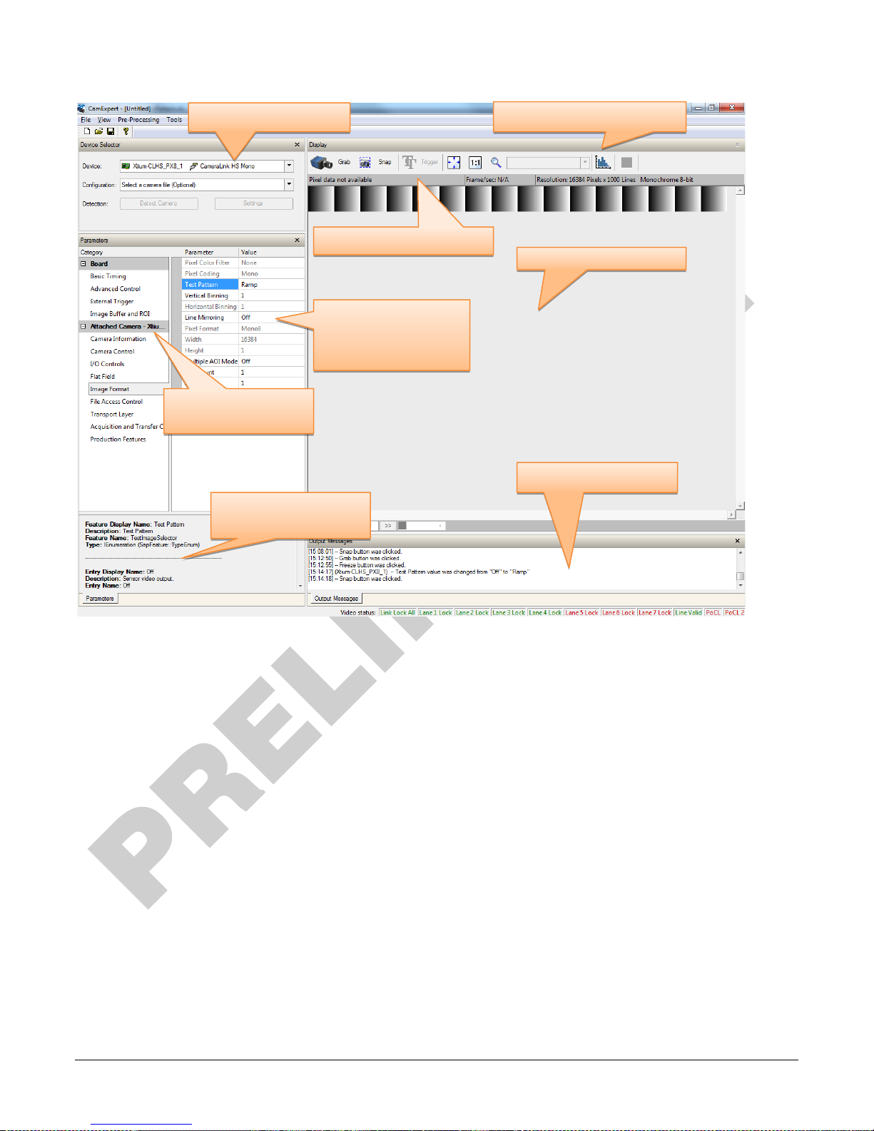
CamExpert Panes
The various areas of the CamExpert tool are described in the figure below. Device categories and
parameter features are displayed as per the device’s XML description file. The number of
parameters shown is dependent on the View mode selected (Beginner, Expert, Guru – see
description below).
16 • Camera Operation Linea CLHS Series Camera
Page 19
Device Selection Menu
Parameter Category
Selection
Feature Values
Quick Guide
CamExpert Control Buttons
Acquisition Information
Parameter Features
Grey read-only
Black are changeable
Message Window
• Device Selector pane: View and select from any installed Sapera acquisition device. After a
device is selected, CamExpert will only present parameters applicable to that device. Optionally
select a camera file included with the Sapera installation or saved by the user.
• Parameters pane: Allows viewing or changing all acquisition parameters supported by the
acquisition device. CamExpert displays parameters only if those parameters are supported by
the installed device. This avoids confusion by eliminating parameter choices when they do not
apply to the hardware in use.
• Display pane: Provides a live or single frame acquisition display. Frame buffer parameters are
shown in an information bar above the image window.
• Control Buttons: The Display pane includes CamExpert control buttons. These are:
Linea CLHS Series Camera Camera Operation • 17
Page 20
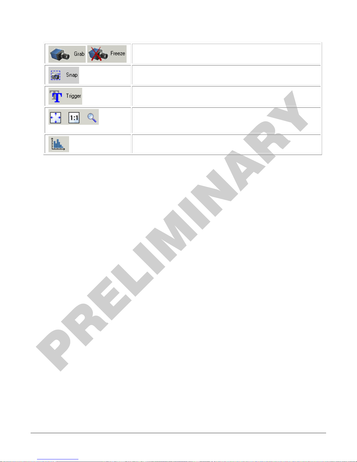
Acquisition control button:
Click once to start live grab, click again to stop.
Single frame grab:
Click to acquire one frame from device.
Software trigger button:
With the I/O control parameters set to Trigger Enabled / Software Trigger
type, click to send a single software trigger command.
CamExpert display controls:
(these do not modify the frame buffer data)
Stretch (or shrink) image to fit, set image display to original size, or zoom
the image to any size and ratio. This does not affect the acquisition.
Histogram / Profile tool:
Select to view a histogram or line/column profile during live acquisition.
• Output pane: Displays messages from CamExpert.
CamExpert View Parameters Option
All camera features have a Visibility attribute which defines its requirement or complexity. The
states vary from Beginner (features required for basic operation of the device) to Guru (optional
features required only for complex operations).
CamExpert presents camera features based on their visibility attribute. CamExpert provides quick
Visibility level selection via controls below each Category Parameter list [ << Less More >> ]. The
user can also choose the Visibility level from the View ∙ Parameters Options menu.
Creating a Camera Configuration File in the Host
• When using the Teledyne DALSA Sapera SDK – the CCF is created automatically via a save.
• When using a 3
automatic. Simply follow the 3
• If the SDK is based on GenAPI 2.3 or lower, the user must call the command
DeviceFeaturePersistenceStart before using the SDK Save Camera method and the command
DeviceFeaturePersistenceEnd at the end of the save function.
rd
party SDK application, if that SDK supports GenAPI 2.4, then the process is
rd
party Save Camera method as instructed.
18 • Camera Operation Linea CLHS Series Camera
Page 21
The following sections describe typical operations performed with the camera. The descriptions rely
on the feature-based Camera Link GenCP protocol, using the Sapera CamExpert application.
If you are using a different application, the display configuration will look different, but the
category, parameter (feature) names, and possible values will be the same. References to related
ASCII commands are provided.
Factory Settings
The camera has been calibrated and configured at the factory to be ready for operation when first
powered up. The camera ships and powers up for the first time with the following factory settings:
• Maximum horizontal width (16,384 pixels)
• Internal trigger, line rate 10 kHz
• Internal exposure control, exposure time 50 µs
• Offset 0, Gain 1x (lowest value)
• Flat field calibration is not active, as this feature is dependent on your light source and lens
Open the CamExpert Panes
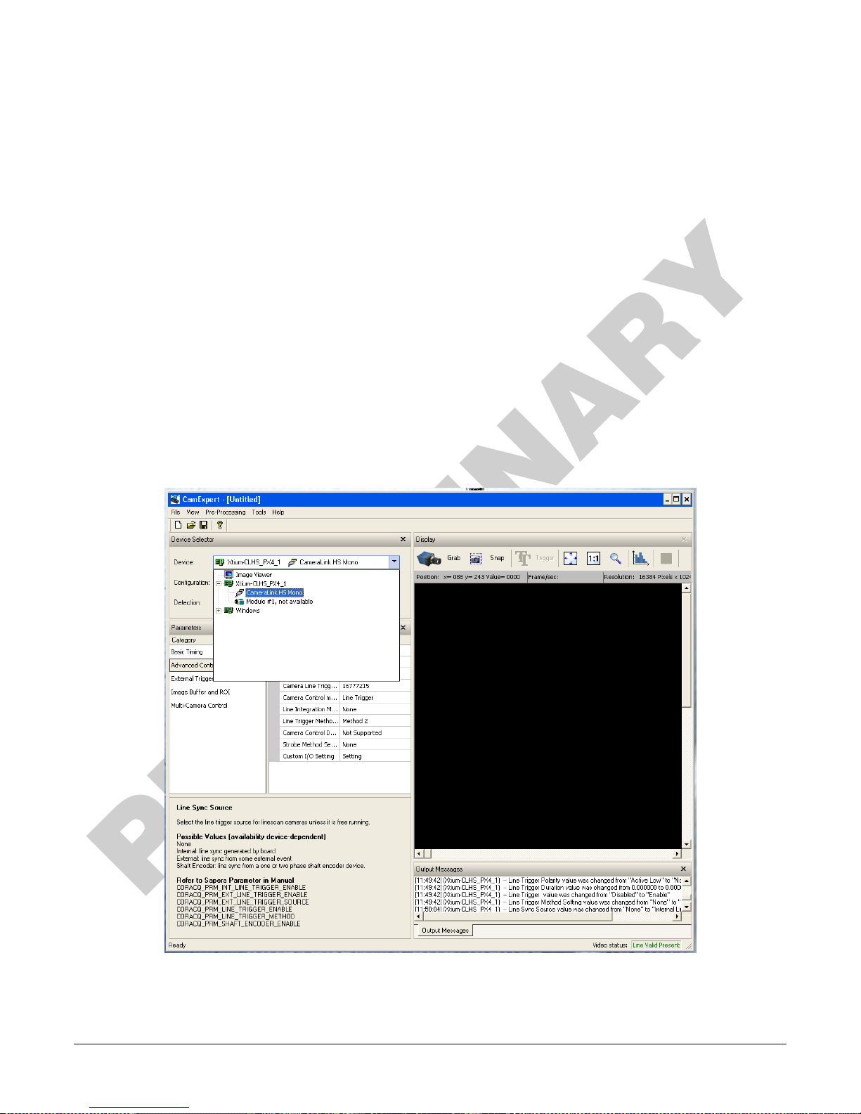
CamExpert, first instance: select Camera Link HS Mono from the Device drop-down menu:
Figure 2. CamExpert Frame Grabber Control Window
Linea CLHS Series Camera Camera Operation • 19
Page 22
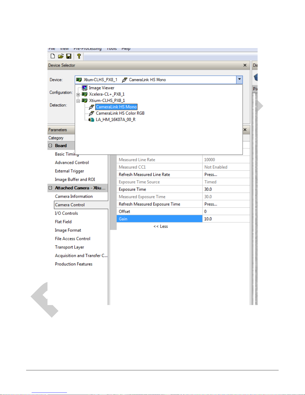
CamExpert, second instance: select LA_HM_16k07A_00_R from the Device drop-down menu.
Figure 3. CamExpert Camera Control Window
At this point you are ready to start operating the camera in order to acquire images, set camera
functions, and save settings.
20 • Camera Operation Linea CLHS Series Camera
Page 23

Typical Setup and Evaluation
Optical Configuration
Typically, the first thing you want to do is to evaluate the camera’s image quality under operating
conditions similar to those you will use in your application. To do this, take the following steps:
• The illumination, lens magnification, and focus should be set up as per you application.
• Getting the magnification right is best accomplished by setting the object-to-sensor
distance. Use the formula lens focal length x (2 + 1/magnification + magnification) to
calculate this distance. Magnification equals the sensor pixel size (7.04 µm or 3.52 µm ) /
(your object pixel size in µm).
• The back focal distance from the front plate to the sensor is 12 mm. For complete
mechanical specifications refer to the Mechanical Specifications section.
Camera Timing & Control
It is easiest and quickest to evaluate the camera using the internal timing setups for line rate and
exposure time. The camera starts up in the default configuration of Camera Link full, 10 kHz line
rate and 50 µsec exposure time.
• If this line rate is too slow for your application, you will get a compressed image in the scan
direction. To increase the line rate, use the Internal Line Rate parameter in the Camera
Control category.
• Adjust the exposure time; refer to the Exposure Controls section.
• Set your camera direction; refer to the Pixel Readout Direction (Mirroring Mode) section.
Acquiring an Image
You can now begin imaging.
• Use the system gain to adjust the camera output to achieve the desired response. The
system gain range is from 1x to 10x. Refer to the Gain and Black Level (Offset) section.
• Once you have a suitable response, you can now focus the lens.
• The image may be darker at the edges due to lens vignetting, but this will be improved once
the camera is calibrated.
• Calibration is performed using a white reference where your object is normally located.
Refer to the Calibrating the Camera section. When calibrated, you should see an image from
the camera that is flat field corrected with the lens at the target level you set.
You are now ready to evaluate the image quality of the camera under your operating conditions.
Linea CLHS Series Camera Camera Operation • 21
Page 24
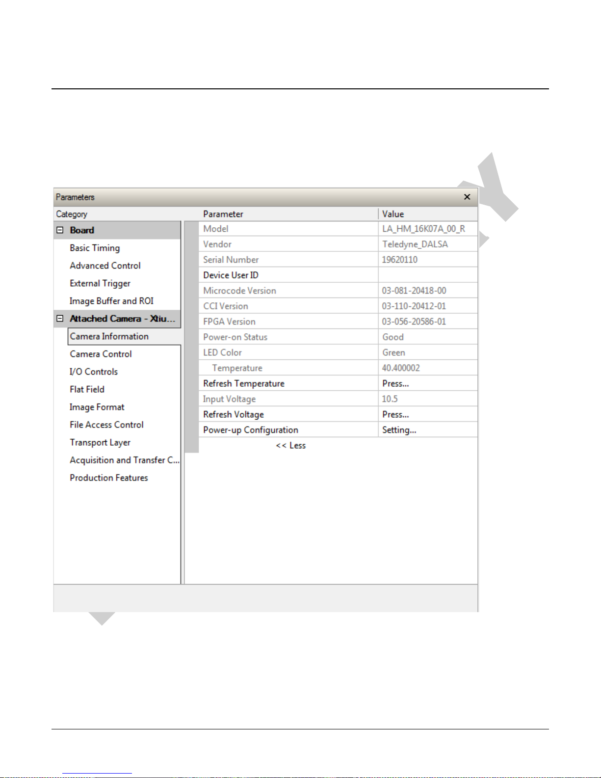
Check Camera and Sensor Information
Camera and sensor information can be retrieved via a controlling application—for example, the
CamExpert GUI shown in the following examples. Parameters such as camera model, firmware
version, sensor characteristics, and so forth, are read to uniquely identify the connected device.
The parameters used to select, load and save user sets are grouped together under the Camera
Information > Power-up Configuration category.
Verify Temperature and Voltage
To determine the voltage and temperature at the camera, use the Refresh Voltage and Refresh
Temperature features.
The temperature returned is the internal temperature in degrees Celsius. For proper operation this
value cannot exceed 80 °C. If the camera exceeds the designated temperature it will stop imaging
22 • Camera Operation Linea CLHS Series Camera
Page 25
measurement can be used to set the applied voltage to the camera.
and the LED will turn red. After you have diagnosed and remedied the issue use the Restart
Camera function.
Note: The voltage displayed is the camera’s input voltage. The voltage measurement
feature of the camera provides results within 1% of the actual voltage. The
Pixel Format
Use the Pixel Format feature, found in the Image Format category, to select the format of the
pixel to use during image acquisition as either Mono 8 or Mono 12 bit depth.
Image Format
Parameter Description
Pixel Format Sets the sensor pixel format. Possible values are:
Mono 8*
Mono 12
*Only available format for Full and Deca Camera Link configurations.
Linea CLHS Series Camera Camera Operation • 23
Page 26
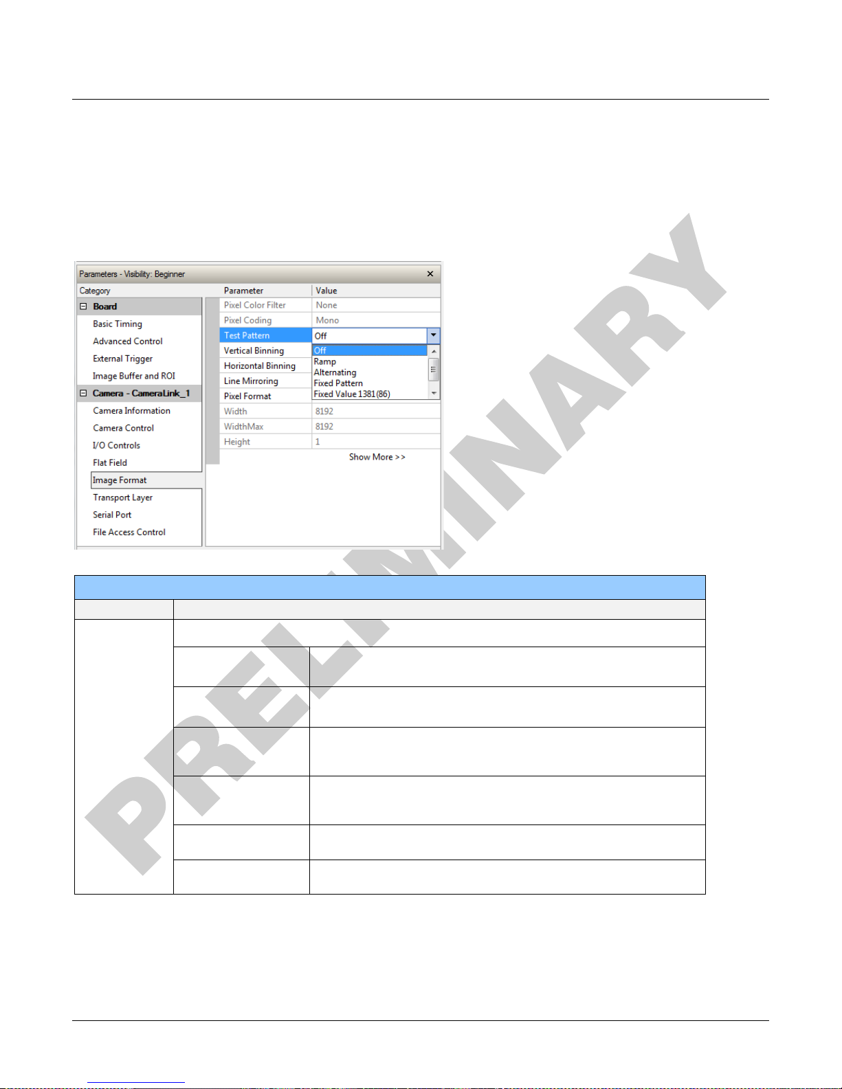
Internal Test Image Generator
The camera includes a number of internal test patterns which can easily confirm camera cable
connections or driver installations, without the need for a camera lens or proper lighting. The
patterns are subject to camera processing, such as binning functions.
Use CamExpert to easily enable and select any test pattern from the drop menu while the camera
is not in acquisition mode. Select live grab to see the pattern output.
The Test Pattern feature is available in the Image Format category:
Image Format
Parameter Description
Test Pattern
Enable camera sensor test pattern. Possible values are:
Off
Ramp
Alternating
Fixed Pattern
Fixed Value 1381(86)
Fixed Value 32(2)
Image is from the camera sensor.
Image is filled horizontally with an image that goes from the darkest
possible value to the brightest.
Alternating values. For 12-bit output, pixel values alternate between
1381 (0x565) and 2746 (0xABA). For 8-bit output, pixel values
alternate between 86 (0x56) and 172 (0xAC).
8 pixel cycling pattern. For 12-bit output, the pattern is
0x120|0x020|0x130|0x030|0x140|0x040|0x150|0x050. For 8-bit
output, the pattern is 0x12|0x02|0x13|0x03|0x14|0x04|0x15|0x05.
Fixed Grey Value. For 12-bit output: pixel value = 1381 (0x565). For
8-bit output: pixel value = 86 (0x56).
Fixed Grey Value. For 12-bit output: pixel value = 32 (0x20). For 8-bit
output: pixel value = 2 (0x2).
24 • Camera Operation Linea CLHS Series Camera
Page 27
operating conditions as possible.
Video
Output
Video
Digital Processing
(monochrome
)
FPN
correction
PRNU
correction
Offset Gain
To calibrate FPN:
Features: flatfieldCorrectionMode
fflatfieldCalibrationSampleSize
flatfieldCalibrationFPN
To calibrate PRNU:
Features: flatfieldCorrectionMode
flatfieldCalibrationSampleSize
flatfieldCalibrationPRNU
flatfieldCorrectionAlgorithm
flatfieldCorrectionTarget
-
X
-/+
X
To set black level offset:
Features: BlackLevel
To set gain:
Features: Gain
Calibrating the Camera
Important Note: to ensure best results, the conditions under which you calibrate the
camera (for example, temperature and illumination) should be as close to the actual
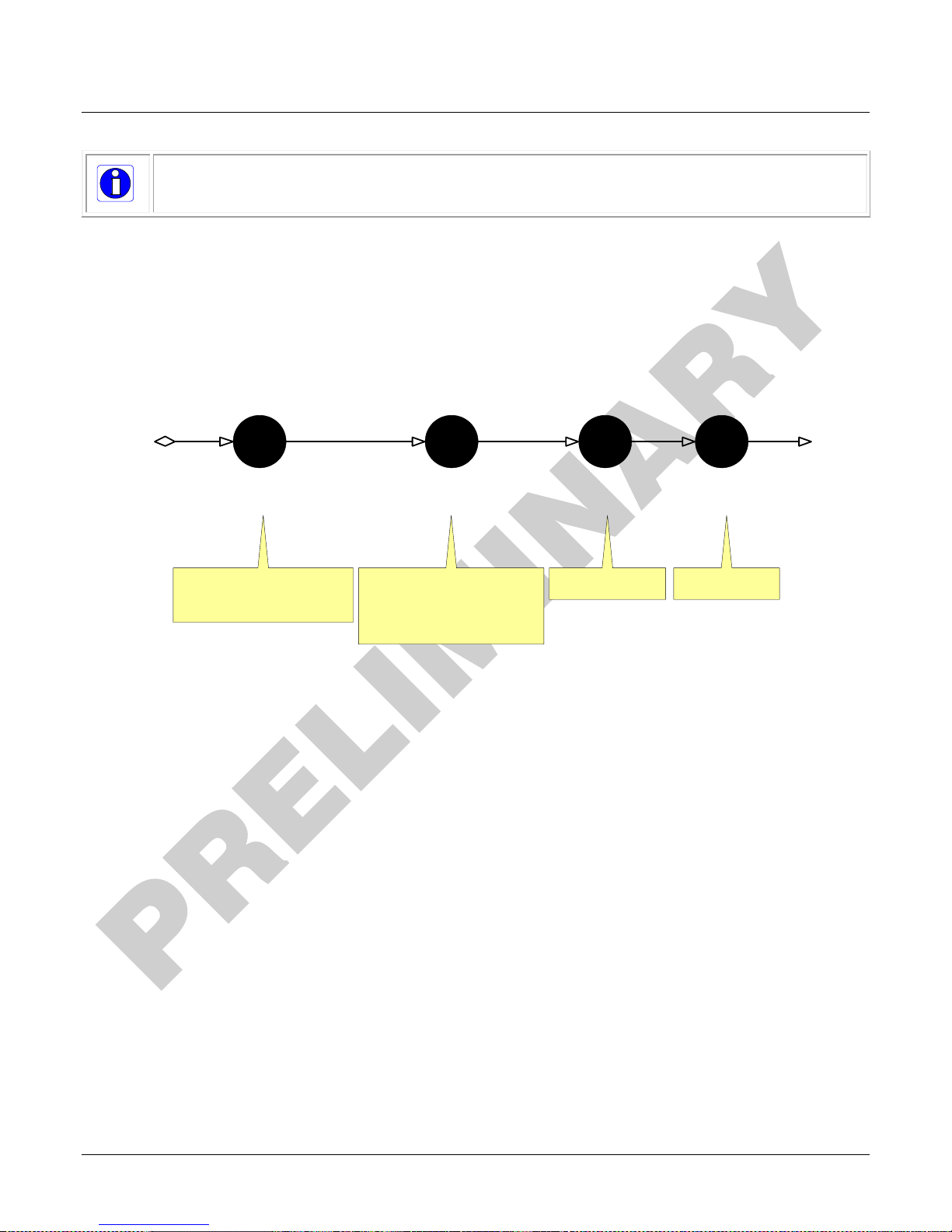
The goal of calibration is for the camera to produce a uniform output image at a desired level while
imaging a uniform white object under conditions equal to the application’s optical setup. Flat field
coefficients are made up of an offset and gain for each pixel. These are the first user corrections
applied to the image. The flat field coefficients are saved and loaded with the user set.
The following diagram illustrates the camera’s digital processing chain and associated GeniCam
features.
To calibrate the camera’s flat field coefficients:
• Configure the camera to the required EXSYNC and exposure timing, and adjust the light
level for normal operation. If used, any horizontal or vertical binning should also be applied.
• Set the system gain to a value that best suits the application; refer to the section Gain and
Black Level (Offset) for more information on setting these values.
• The lens should be at the required magnification and aperture and slightly unfocused to
avoid introducing granularity or details in the reference image (when calibration is complete,
refocus the lens).
• As the white reference is located at the object plane, any markings or contaminants on its
surface (that is, dust, scratches, smudges) will end up in the calibration profile of the
camera. To avoid this, use a clean white plastic or ceramic material rather than trying to
rely on a paper reference. (Ideally, the white object will be moving during the calibration
process, as the averaging process of the camera will diminish the effects of any small
variation in the white reference.)
• Adjust the system gain until the peak intensity is at the desired DN level and then calibrate
the fixed pattern noise (FPN). Use a lens cap to ensure that no light reaches the sensor.
• Once complete, remove the lens cap and perform a photo response non-uniformity (PRNU)
calibration using the desired target value (in DN). You want all the pixels to match. This
target value should be higher than the peak values you saw while first setting up the
camera.
Linea CLHS Series Camera Camera Operation • 25
Page 28
• After several seconds the PRNU calibration will end and the correction coefficients will be
enabled. The system gain remains as first set.
• The coefficients and gain parameters, timing and control configuration can be stored in any
one of eight user sets and automatically retrieved at power-up or by user selection.
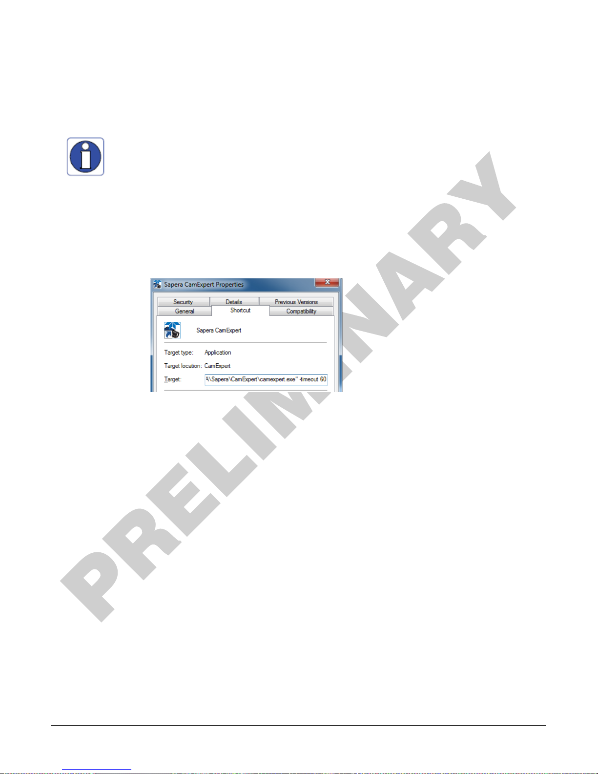
CamExpert has a default timeout of 20 seconds per command, which is too
short for the FFC calibration to run fully. You can change the default timeout by
setting a command line argument in the short-cut:
• Right-click on the short-cut in the start menu and select Properties.
• In the Target field, add the switch –timeout 60 (See below)
This increases the command timeout to 60 seconds.
Note that you must include a character space between the closing
quotation mark in the target and the hyphen before the timeout value.
• Repeat for desktop short-cut
26 • Camera Operation Linea CLHS Series Camera
Page 29
Sending this value will reset all current coefficients (offsets to
Flat Field Parameters
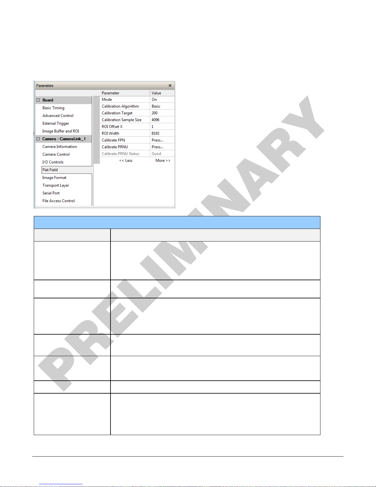
This Flat Field category contains a number of features that are used to correct image distortion
due to lens vignetting and uneven illumination.
Flat Field
Parameter
Mode Off – Flat field correction coefficients are not applied.
Calibration Algorithm Basic – Direct calculation of coefficients based on current average line
Calibration Target After calibration all pixels will be scaled to output this level.
Calibration Sample Size Number of lines to average when calibrating.
ROI Offset X Together with “ROI Width”, specifies the range of pixels to be calibrated.
Description
On – Flat field correction coefficients are applied.
Initialize –
0 and gains to 1x).
values and target.
Range depends on pixel format:
• 8-bit: 0 to 255 DN
• 12-bit: 0 to 4095 DN
Possible values: 2048 or 4096
Pixel coefficients outside this range are not changed. It is possible to
calibrate different regions sequentially.
ROI Width Width of ROI, in pixels.
Calibration FPN Save average line (of “Calibration Sample Size” rows). This is the first
user correction applied – it is subtracted from each line.
This feature may not be of use to many users as the camera already
subtracts true “dark current”, but it may be useful for some to provide a
per pixel offset correction.
Linea CLHS Series Camera Camera Operation • 27
Page 30
• Range 0 to 511 DN (12-bit) or 0 to 31 DN (8-bit)
• Default value is 0 DN for each pixel
Calibration PRNU Use “Correction Algorithm” to calculate the per pixel gain to achieve the
specified target output.
• Range 0 to 15.9998x
• Default 1x
Gain and Black Level (Offset)
The gain and black level controls can make small compensations to the acquisition in situations
where lighting varies and the lens iris cannot be easily adjusted. Optimal gain and black level
adjustments maximizes the camera’s dynamic range for individual imaging situations.
Use the Offset and Gain features to maximize the use of the output dynamic range (especially
when pixel format is less than 12-bits). Typical use is to subtract minimum pixel value expected
and then adjust the gain to up the maximum pixel value to approach full scale.
Features and limitations are described below.
• Black Level offset is expressed as a digital number providing a ± offset from the factory
setting. The factory setting optimized the black level offset for maximum dynamic range under
controlled ideal dark conditions.
• Digital Gain is expressed as a multiplication factor. Note that increasing digital gain does not
increase the low level resolution and increases the sensor noise proportionately.
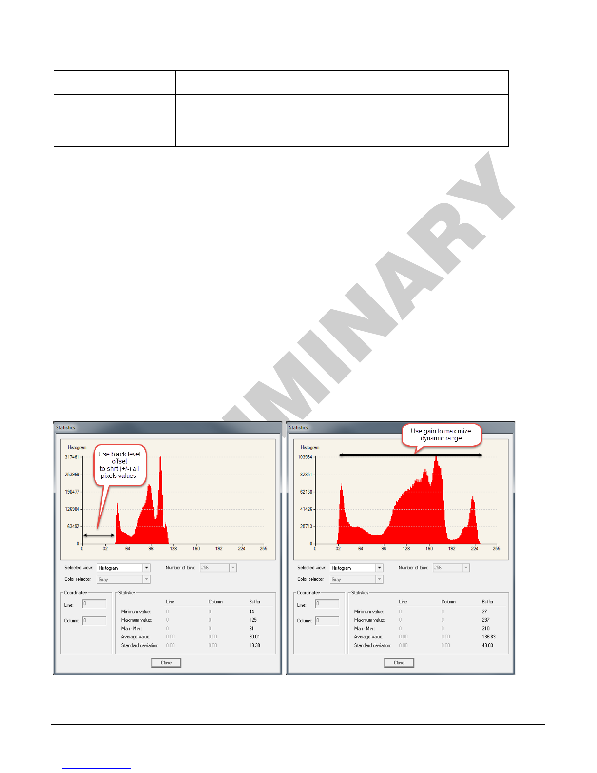
A histogram or line profile (available in CamExpert) can provide useful information to determine
the optimal settings for the typical image expected for an application. For example, the following
histograms illustrate the effect of offset and gain applied to the original image to try to maximize
the dynamic range.
28 • Camera Operation Linea CLHS Series Camera
Page 31
12-bit mode
available range is -512 to +511.
8-bit mode
available range is -32 to +31.
Floating point digital multiplier applied to each pixel. Set the gain as an amplification
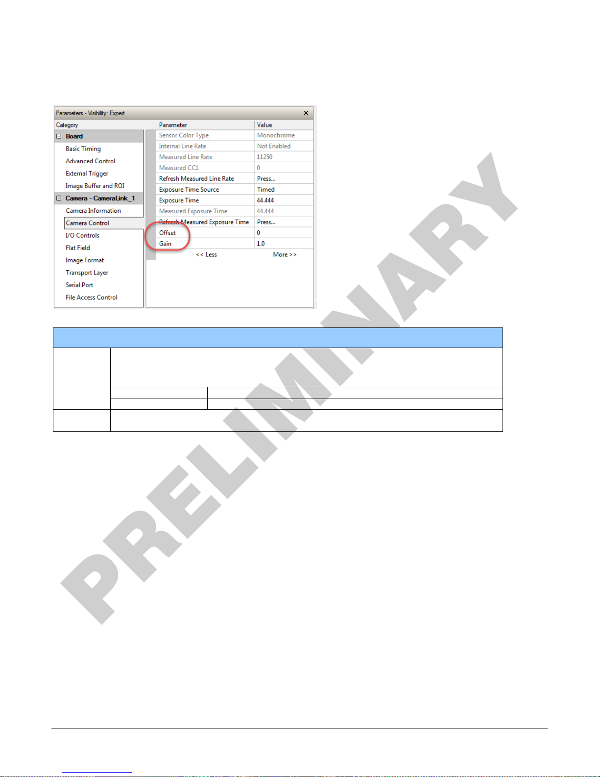
The parameters that control gain and black level are grouped together in the Camera Control
category:
Camera Control
Offset
Gain
Single value added to each pixel. Apply a digital addition after an FPN correction: ±
1/8 of available range. Positive values may be used to measure dark noise.
Depending on the the pixel format, different offset ranges are available:
factor applied to the video signal across all pixels: 1x to 10x.
Linea CLHS Series Camera Camera Operation • 29
Page 32
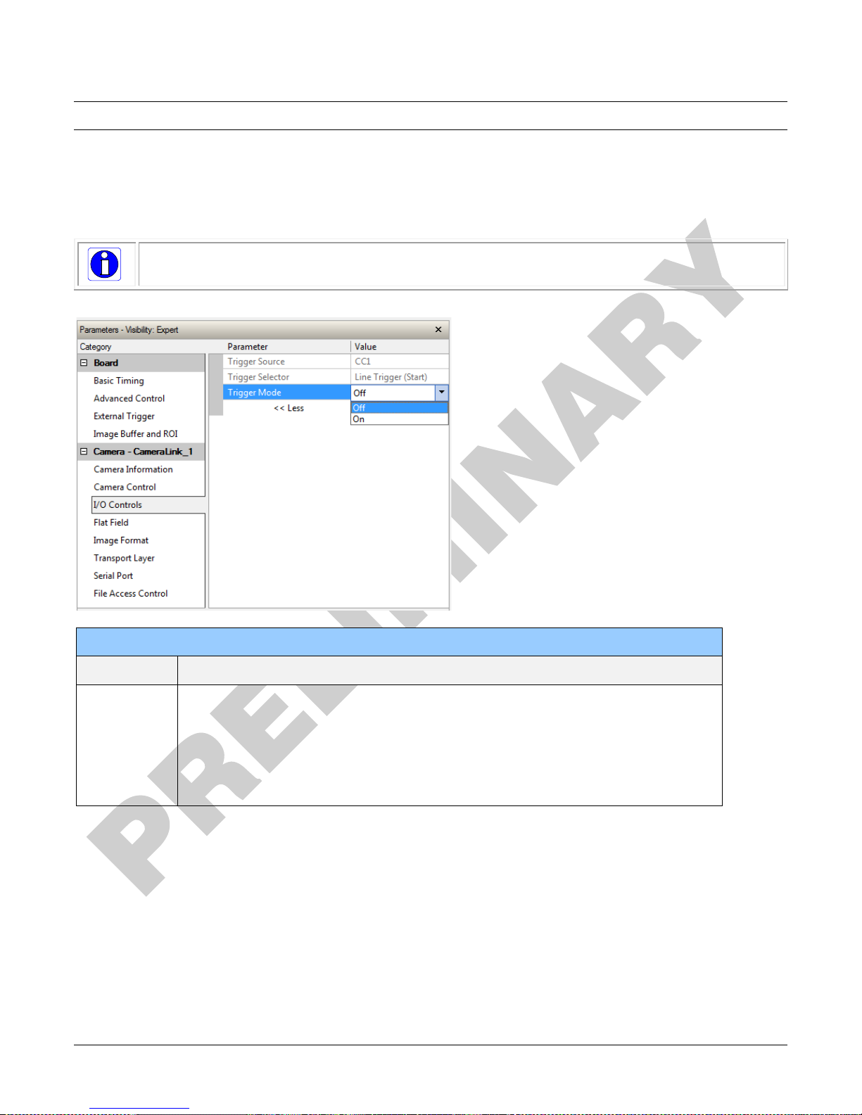
Trigger Modes
The camera’s image exposures are initiated by a trigger event. The trigger event is either a
programmable internal signal used in free running mode, an external input used for synchronizing
exposures to external triggers, or a programmed function call message by the controlling
computer. These triggering modes are described below.
Note: The Trigger Mode feature can only be adjusted when the Exposure Time Source
parameter is set to “Timed”.
The Trigger Mode feature is available in the camera’s I/O Controls category:
I/O Controls
Parameter Description
Trigger Mode
• Off: Internal trigger (trigger disabled): The camera free-running mode
has a programmable internal timer for line rate and a programmable
exposure period.
• On: External trigger (trigger enabled): Exposures are controlled by an
external trigger signal. The external trigger signal is the Camera Link
control line CC1.
30 • Camera Operation Linea CLHS Series Camera
Page 33
Exposure
programmable
Exposure
programmable
Exposure
Exposure Controls
Exposure control is defined as the start of exposure and exposure duration. Exposure control
modes define the method and timing of controlling the sensor integration period. The integration
period is the amount of time the sensor is exposed to incoming light before the video line data is
transmitted to the controlling computer.
The camera can grab images in one of three ways, as described in the following table:
Description
Internal Programmable
Line Rate
Internal, programmable Internal
Exposure Time
Trigger Source
Internal
External Programmable
External Trigger Width
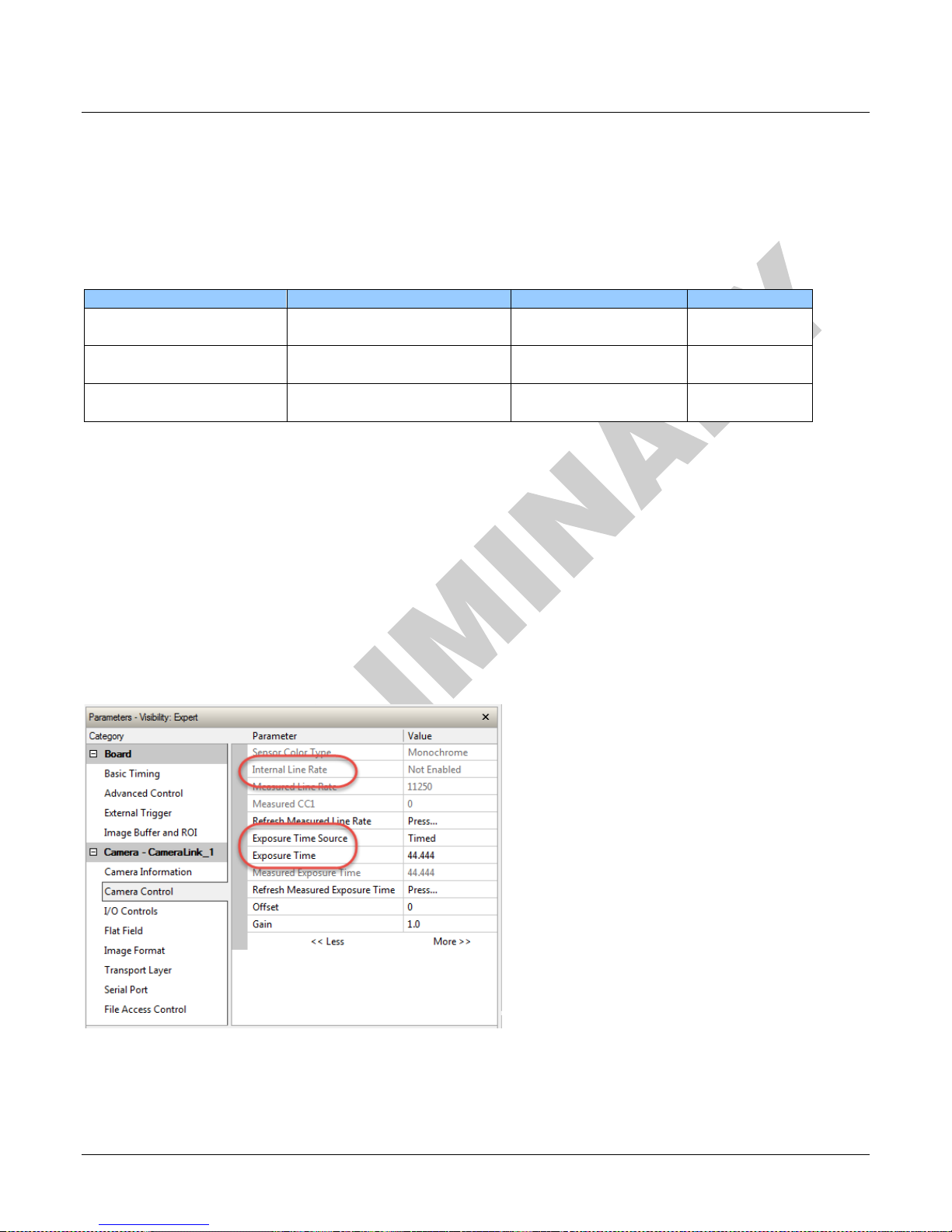
You determine the three imaging modes using a combination of the Exposure Time Source
parameters (including I/O parameters), Exposure Time and Internal Line Rate parameters.
• The feature Exposure Time Source selects the controlling method for the exposure.
• The start of exposure can be driven by an internal timer signal, an external trigger signal, or a
software function call.
• For External Trigger signals, the relationship between an external line trigger and the exposure
period is only applicable while the external line trigger does not exceed the maximum allowable
line rate.
• If the external line rate exceeds the maximum line rate allowed for a mode, the camera will
continue to output data at its maximum line rate. Though no image artifacts associated with
over-speed will occur, you may notice that under over-speed conditions the image will appear
compressed and the apparent distance travelled will be reduced.
The relevant exposure control features are grouped in the Camera Control category:
Controlled by EXSYNC pulse Internal
Controlled by EXSYNC pulse External (EXSYNC) External
External
Linea CLHS Series Camera Camera Operation • 31
Page 34
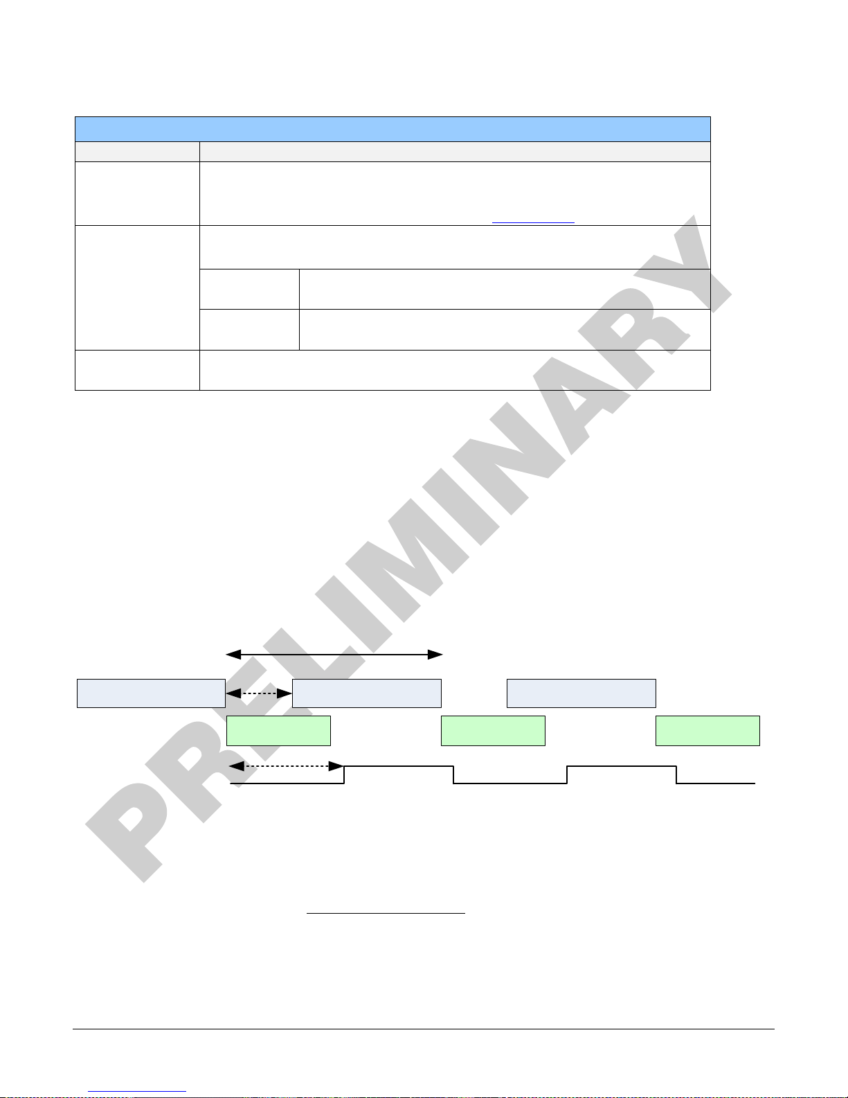
Programmable Exposure
1
Programmable Exposure
1
Programmable Line Time
> 2 µs
Programmable Exposure
1
Sensor Readout
2
Sensor Readout
2
Sensor Readout
2
LVAL delay
3
LVAL
Camera Control
Parameter Description
Internal Line
Rate
Camera line rate in a range from 300 Hz up to 71 kHz.
This feature is only available when the camera is in Internal Mode (free
running): that is, the line trigger is disabled (Trigger Mode off).
Exposure Time
Source
Set the operation mode for the camera’s exposure. Trigger Width is only
available when Trigger Mode is enabled.
Trigger
Width
Uses the width of the current line trigger signal pulse to
control the exposure duration.
Timed The exposure duration time is set using the Exposure Time
feature and the exposure starts with the Line Start event.
Exposure Time Sets the exposure time (in microseconds). Exposure Time Source feature
must be set to Timed.
Internal Programmable Exposure
The camera in the Internal Programmable Exposure mode is the default free- running mode with
the external trigger off and internal exposure control. This mode is not synchronized to an external
signal. Line rate is the dominant factor when adjusting the line rate or exposure time. When setting
the line rate exposure time will decrease (if necessary) to accommodate the new line rate. When
adjusting the exposure time the range is limited by the line rate and has the following features:
• The Trigger Source feature (see I/O Control category) selects an internal signal as trigger.
• Programmable internal trigger, where the maximum line rate limit is related to the Exposure
Time feature.
• Exposure duration is user programmable (exposure maximum is dependent on the line rate).
Minimum exposure (in µs) is model dependent.
1. Exposure time > 4µs
2. Sensor readout tiµe = 20.8 µs
3. LVAL delay = 41µs
To calculate the maximum line rate:
Maximum line rate =
*Exposure time must be greater than 4 µs, and low time greater than greater than 2 µs (16k
model)
32 • Camera Operation Linea CLHS Series Camera
1
(𝑒𝑥𝑝𝑜𝑠𝑢𝑟𝑒 𝑡𝑖𝑚𝑒+𝑙𝑜𝑤 𝑡𝑖𝑚𝑒∗)
Page 35
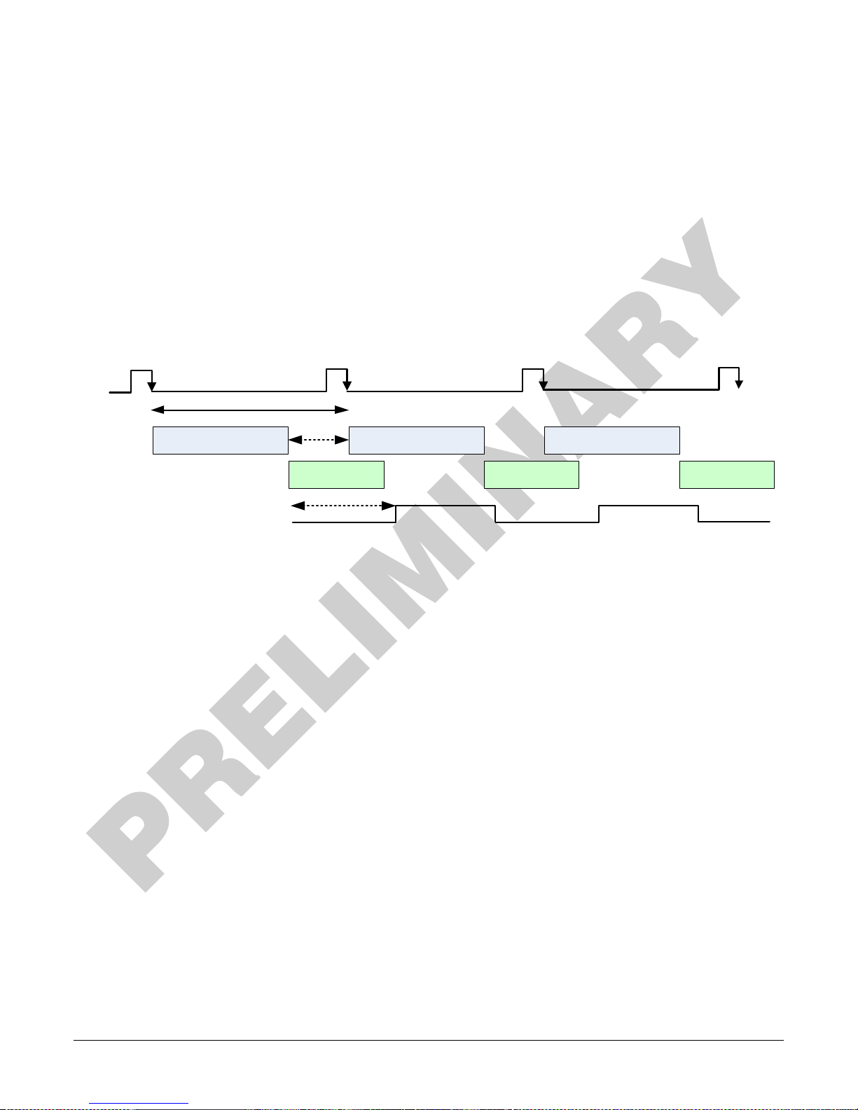
Programmable Exposure
1
Programmable Exposure
1
Line Time
Programmable Exposure
1
Sensor Readout
2
Sensor Readout
2
Sensor Readout
2
LVAL delay
3
LVAL
CC1
> 2 µs
GenICam parameters to set:
• I / O Controls > Trigger Mode > Off
• Camera Control > Internal Line Rate > user value
• Camera Control > Exposure Time > user value
External Programmable Exposure
The External Programmable Exposure mode is similar to Internal Programmable except for the
exposure start being an external user input.
• The TriggerSource feature (see I/O Control category) selects an external signal line as trigger.
• Line rates and exposure limits are as defined for Internal Programmable Exposure.
• The falling edge of the EXSYNC (CC1) signal triggers the start of the internal exposure.
1. Exposure time > 4µs
2. Sensor readout time = 20.8 µs
3. LVAL delay = 41µs
GenICam parameters to set:
• I / O Controls > Trigger Mode > On
• Camera Control > Exposure Time Source > Timed
• Camera Control > Exposure Time > user value
Linea CLHS Series Camera Camera Operation • 33
Page 36
Exposure = X
1
Line Time
Sensor Readout
1
LVAL delay
2
LVAL
CC1
X
1
X
2
X
3
Exposure = X
2
Sensor Readout
1
Exposure = X
3
Sensor Readout
1
> 2 µs
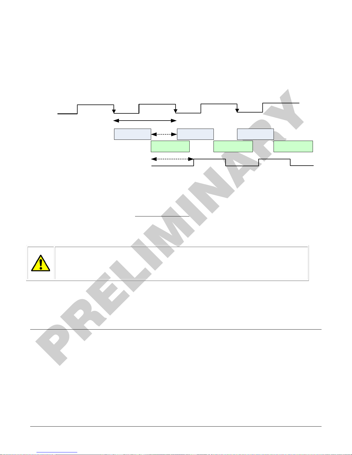
External Trigger Width Exposure
An alternative external trigger mode allows the external signal width to control the exposure
duration. Line readout time remains similar to programmable exposure modes.
• EXSYNC (CC1) sets both the line period and the exposure time.
• The EXSYNC high duration sets the exposure time and the falling edge triggers the start of
exposure.
1. Sensor readout time = 20.8 µs
2. LVAL delay = 41 µs
Note:
Maximum line rate =
(𝑒𝑥𝑝𝑜𝑠𝑢𝑟𝑒 𝑡𝑖𝑚𝑒+𝑙𝑜𝑤 𝑡𝑖𝑚𝑒 ∗)
1
*Exposure time must be greater than 4 µs, and low time greater than 2 µs
Warning! When running external line rate and external exposure time, the line rate
must not exceed 1 / (exposure time + low time). Under these conditions the
exposure time will become indeterminate and result in image artifacts. This is not
the case when running internal exposure control.
GenICam parameters to set:
• I / O Controls > Trigger Mode > On
• Camera Control > Exposure Time Source > Trigger Width
Binning
Binning is the combining of two or more image sensor pixels to form a new combined pixel. A
binned image using the same exposure settings as a non-binned image will show an improved
signal-to-noise ratio, reduced scanning times (due to lower spatial resolution) and save as a
smaller image file size compared with a non-binned image, at the expense of lower image
resolution.
In 2 x 2 binning, 4 physical pixels on the sensor are combined into one image pixel. This operating
mode is ideal for applications that require faster acquisition and processing times and require
greater signal collection.
34 • Camera Operation Linea CLHS Series Camera
Page 37
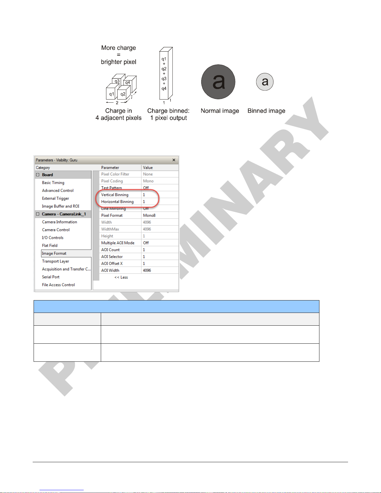
For this camera, the default binning value is 1 x 1,
The Vertical Binning and Horizontal Binning features in the Image Format category
represents the number of horizontal pixels that will be combined (added) together.
Image Format
Parameter
Vertical Binning This feature represents the number of vertical photo-sensitive cells that
Horizontal Binning This feature represents the number of horizontal photo-sensitive cells that
Linea CLHS Series Camera Camera Operation • 35
Description
are combined (added) together: 2.
are combined (added) together.
Page 38
Line Mirroring
Off: All pixels are read out from left to right.
On: All pixels are read out from right to left.
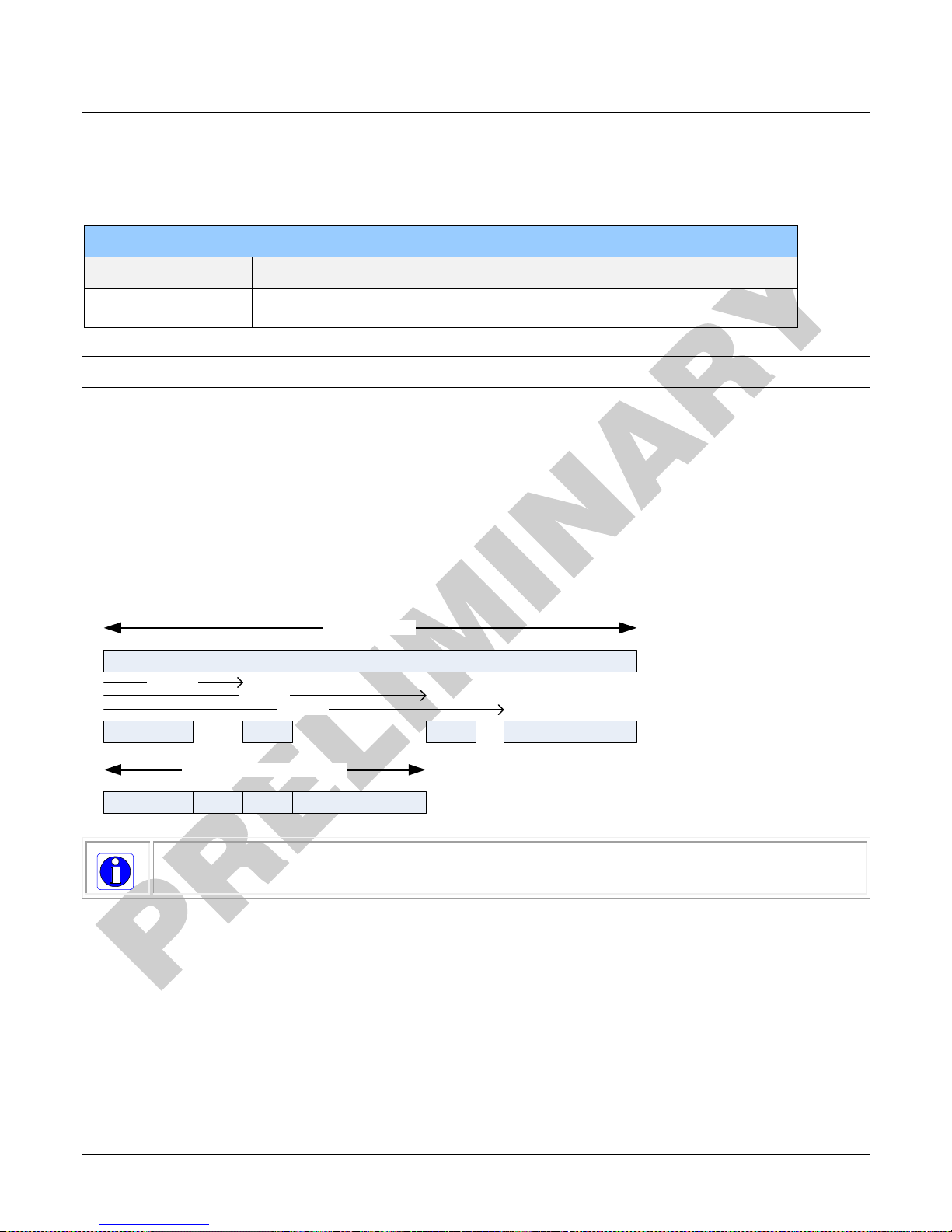
Full Image Width
AOI 1
AOI 2
AOI 3
AOI 4
AOI 2 Offset
AOI 3 Offset
AOI 4 Offset
AOI 1
AOI 2
AOI 3
AOI 4
Resulting Output Image Width
Pixel Readout Direction (Mirroring Mode)
The Line Mirroring feature, in the Image Format category, sets the tap readout from left to right
or from right to left. This feature is especially useful if you want to mount the camera “upside
down.”
Image Format
Parameter Description
Area of Interest (AOI) Setup
The Area of Interest (AOI) feature can be used to reduce the amount of image-data output from
the camera. Use this feature when there are areas in the image that contain unneeded information.
An example where you would use this feature is in an application that is inspecting several
separated lanes of objects with one camera and the image between the lanes can be ignored.
The AOI feature allows from one to four specific areas of the pixel line to be specified where image
data will be output. Since the AOI feature reduces the amount of data output, this has the
additional benefit of allowing the cameras to operate at higher line rates when using base or
medium camera link modes.
Note: The setup of AOI is always with respect to the sensor. Therefore, if you are using the
mirroring mode with AOI, be aware that pixel one will be on the right side of the displayed image.
The AOI commands are grouped in the Image Format category.
To set up an AOI for the camera:
• The AOI mode must first be in the off position.
• Use the AOI Count to select the total number of AOIs desired to a max of 4.
• To set up each AOI individually use the AOI Selector to point to the AOI to be set up.
• AOI Offset X is used indicate the starting pixel of the AOI. The starting pixel of the region
36 • Camera Operation Linea CLHS Series Camera
must be 1 + a multiple of 8 (base, medium, and full modes) or 10 (deca mode).
Page 39
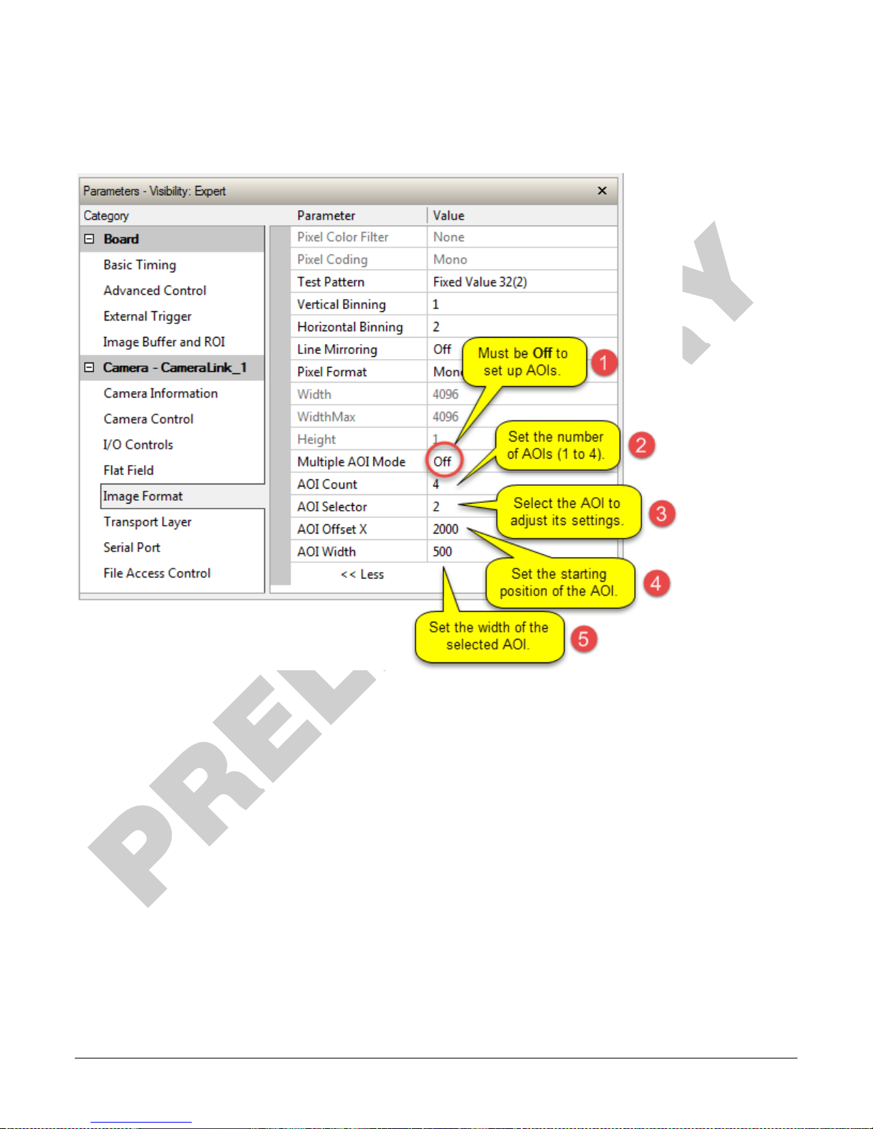
• AOI Width is used to indicate the width of the AOI. Minimum region width is 40 pixels and
must be a multiple of 8 (base, medium, and full modes) or 10 (deca mode).
Linea CLHS Series Camera Camera Operation • 37
Page 40
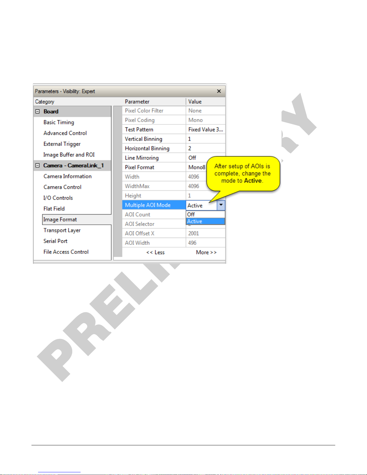
To initiate operation of the AOI once setup:
• The AOI mode must be changed to Active.
• Be sure to set the frame grabber image width to the sum of all AOI widths set up in the
camera.
38 • Camera Operation Linea CLHS Series Camera
Page 41
Saving and Restoring Camera Settings
The parameters used to select, load and save user sets are grouped together under the Camera
Information category. There are 8 user sets available and 1 factory set.
Camera Configuration Selection Dialog
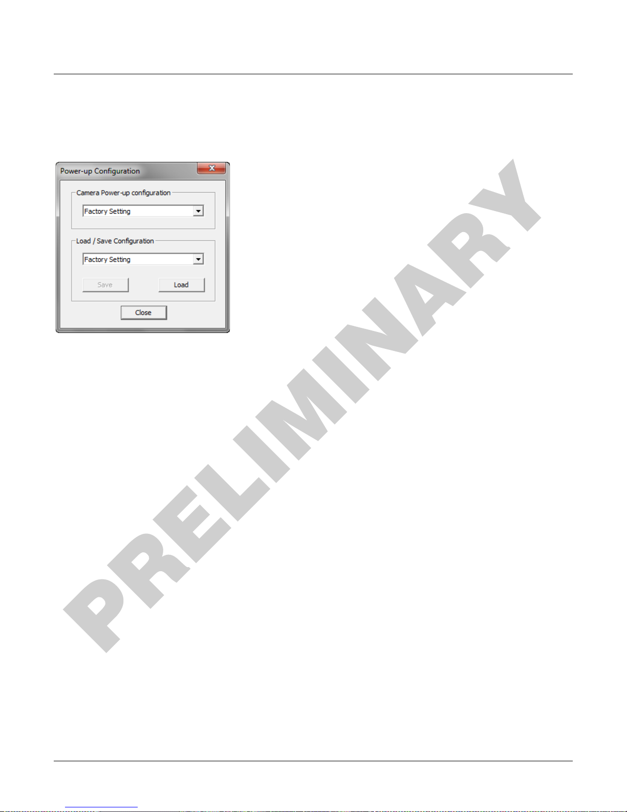
CamExpert provides a dialog box which combines the features to select the camera power-up state
and for the user to save or load a camera state from the camera’s memory.
Camera Power-up Configuration
Either the Factory or one of the User Settings can be used as the default setting and is the set
loaded when the camera is reset of powered up.
The first drop list selects the camera configuration state to load on power-up (see feature
UserSetDefaultSelector). The user chooses from one factory data set or one of 8 possible user
saved states.
User Set Configuration Management
The user setting is the saved set of camera configurations that you can customize, resave, and
restore. By default the user settings are shipped with the same settings as the factory set.
The second drop list allows the user to change the camera configuration any time after a power-up
(see feature UserSetSelector). To reset the camera to the factory configuration, select Factory
Setting and click Load. To save a current camera configuration, select from User Set 1 through
User Set 8, and click Save. Select a saved user set and click Load to restore a saved configuration.
Active Settings for Current Operation
The active setting for the current operation is the set of configurations that are active while the
camera is currently running, including all unsaved changes you have made to the settings before
saving them.
These active settings are stored in the camera’s volatile memory and will be lost and cannot be
restored if the camera resets, is powered down, or loses power.
To save these settings for reuse the next time you power up or reset the camera, or to protect
against losing them in the case of power loss, you must save the current settings. Once saved, the
current settings become the selected User Set.
Linea CLHS Series Camera Camera Operation • 39
Page 42
Type
File
Device Firmware
Microcode (.hex file)
XML
XML file
Miscellaneous
FPGA Code (.bin file)
CCI (.hex file)
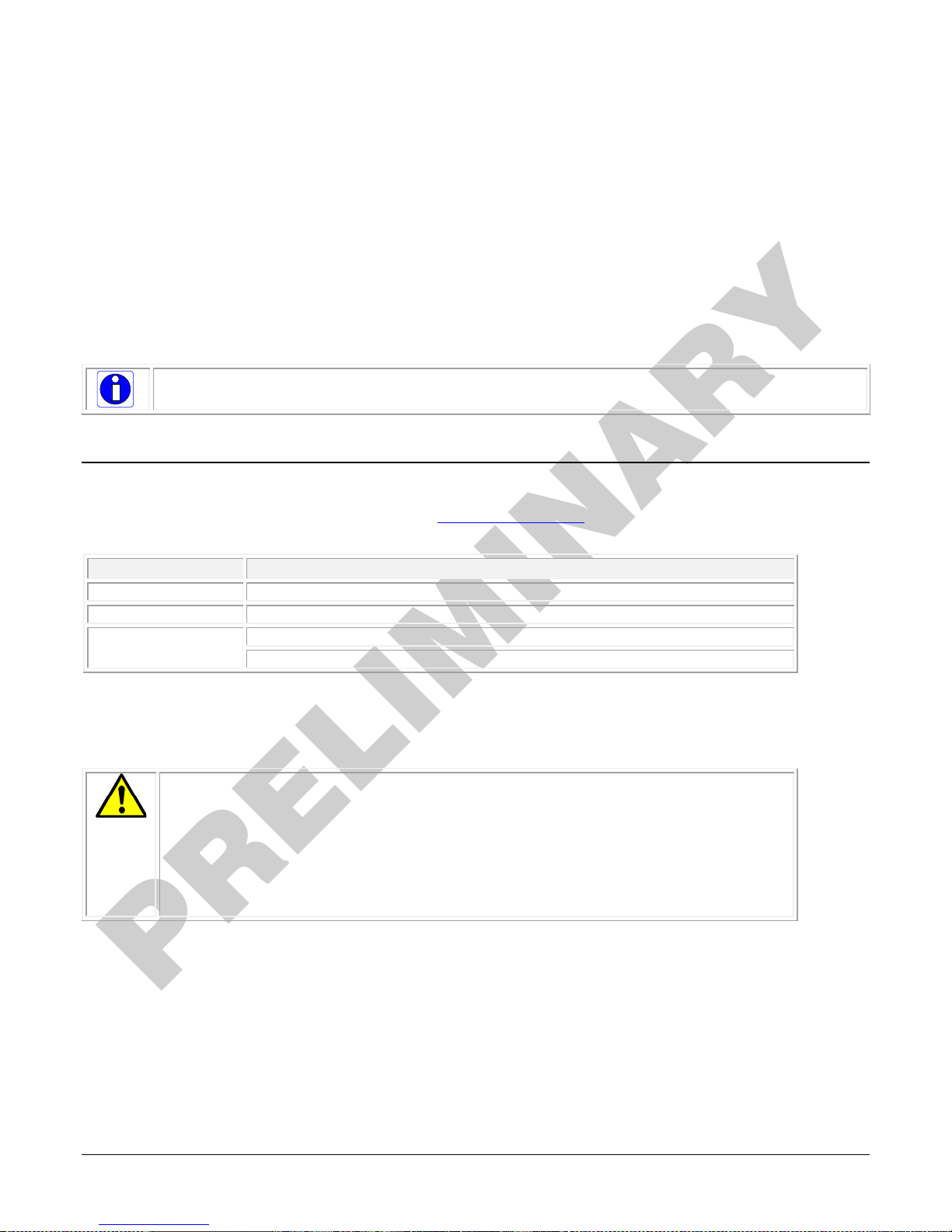
Warning! The camera firmware file versions must all be compatible or the
User Setting
The command User Set Save saves the current settings to non-volatile memory as a User Set.
The camera automatically restores the last saved user settings when it powers up.
To restore the last saved user settings, select the User Set parameter you want to restore and
then select the User Set Load parameter.
Factory Settings
The factory setting is the camera settings that were shipped with the camera and which loaded
during the camera’s first power-up. To load or restore the original factory settings, at any time,
select the Factory Setting parameter and then select the User Set Load parameter.
Note: By default, the user settings are set to the factory settings.
Camera Firmware Updates
The user can upload new firmware using the File Access Control features via Sapera CamExpert.
To update the camera firmware several files must be updated. Files include the following:
After all files have been transferred to the camera (the order is not relevant), reboot or reset the
camera and restart CamExpert to verify the file versions displayed in the Camera Information
category.
camera risks becoming inoperable. Only after all required files are
uploaded to the camera can the camera be reset or rebooted to
activate the new firmware.
Before updating any firmware files verify that the file versions are correct. If
in doubt, contact your Teledyne DALSA representative if you have any
questions before proceeding.
40 • Camera Operation Linea CLHS Series Camera
Page 43
Download a List of Camera Parameters
For diagnostic purposes you may want to download a list of all the parameters and values
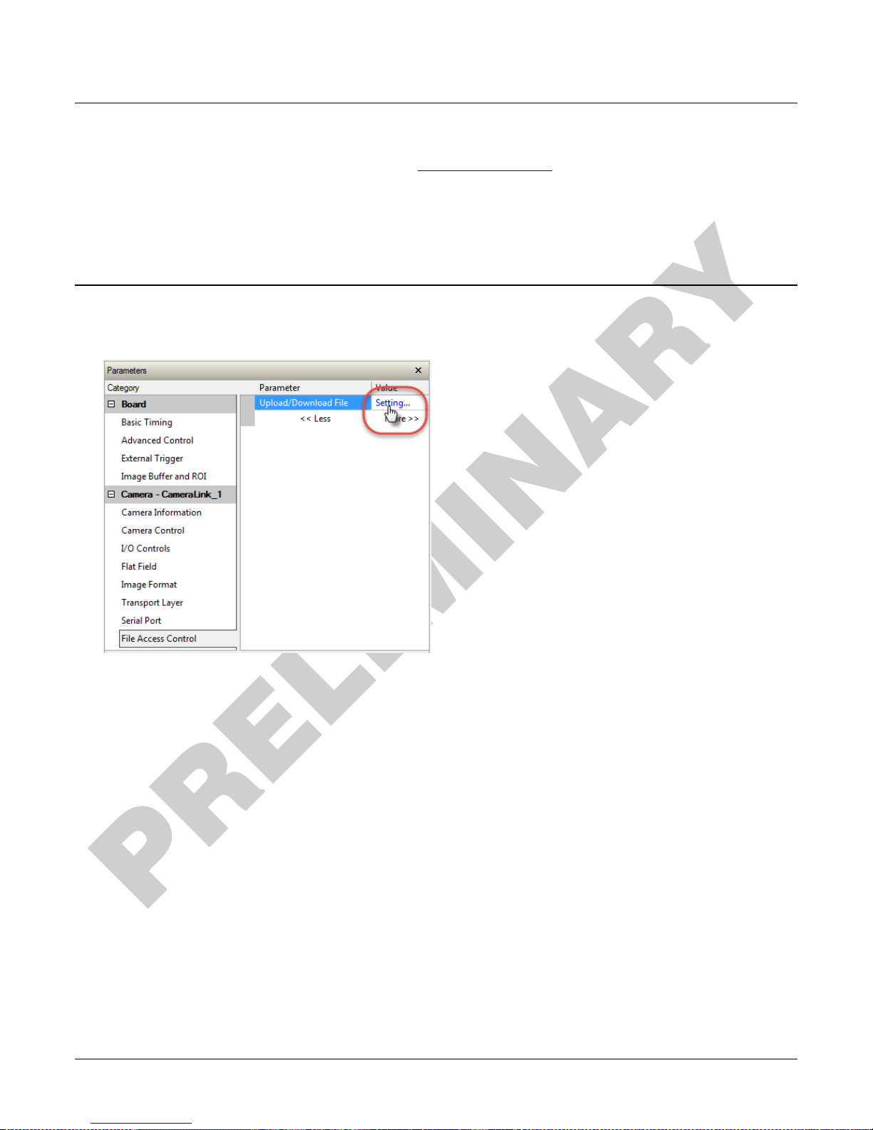
associated with the camera. To do this use the File Access Control
• Select “Miscellaneous” file type
• In the “File selector” drop-down box select “CameraData”.
• Click “Download”.
• Save the text file and send the file to Teledyne DALSA customer support if required.
features via Sapera CamExpert:
File Access via the CamExpert Tool
• In the File Access Control Category, click on the “Setting…” button to open the File Access
Control dialog.
Linea CLHS Series Camera Camera Operation • 41
Page 44
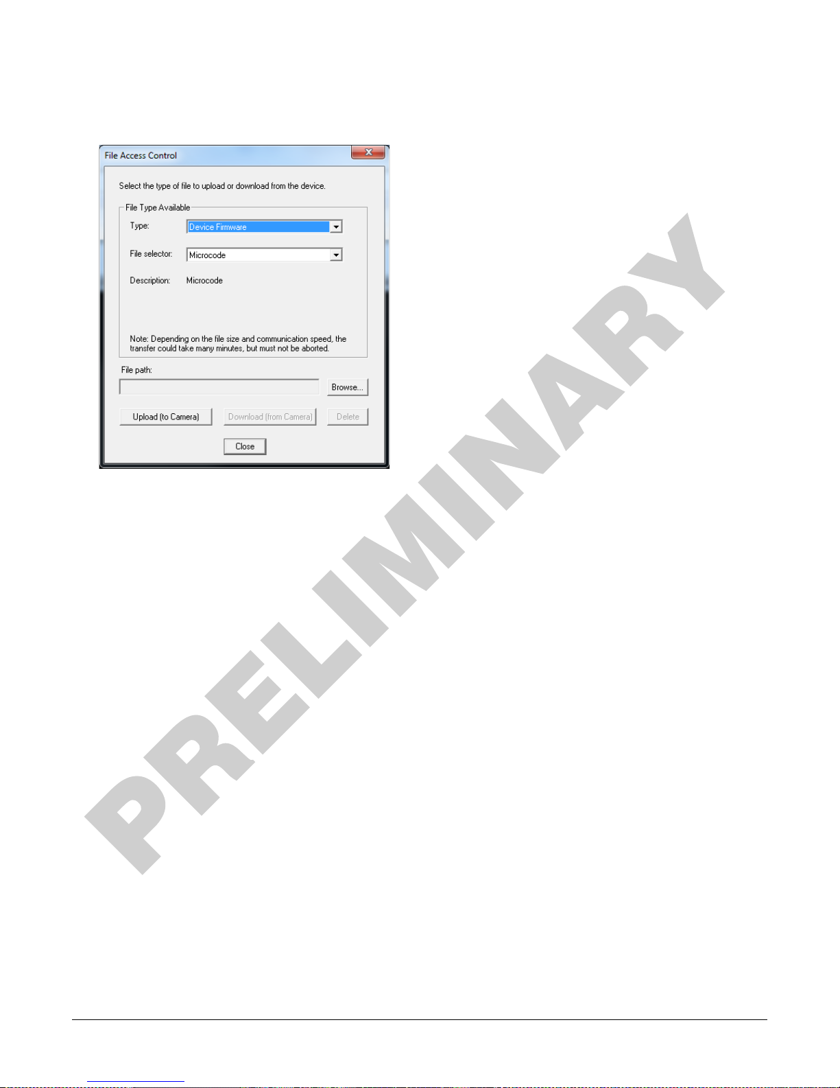
• From the file Type drop menu, select the file type that will be uploaded to the camera. This
CamExpert tool allows quick firmware changes or updates.
• From the File Selector drop menu, select the camera’s memory location for the uploaded data.
This menu presents only the applicable data locations for the selected file type.
• Click the Browse button to open a standard Windows Explorer window.
• Select the specific file from the system drive or from a network location.
• Click the Upload button to execute the file transfer to the camera.
• Note that firmware changes require a device reset command from the Transport Layer Controls.
42 • Linea CLHS Series Camera
Page 45
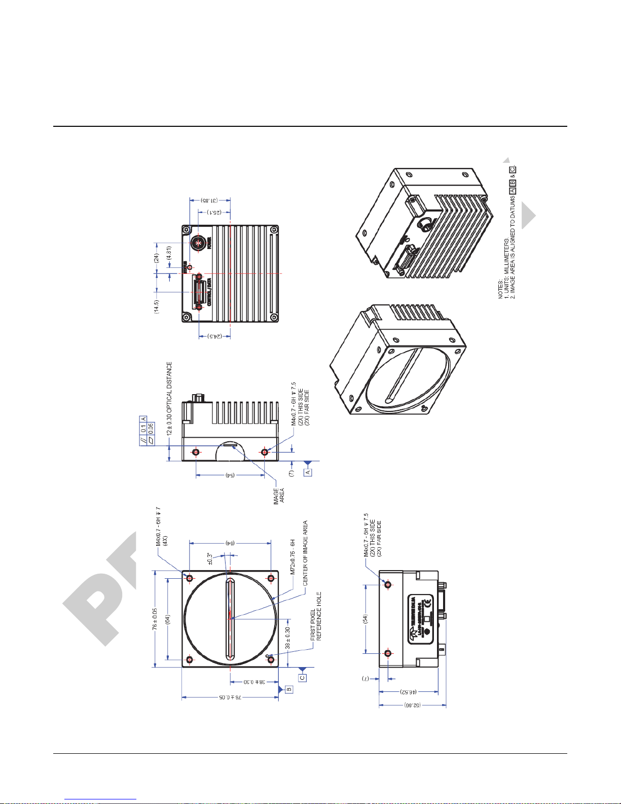
Technical Specifications
Mechanical Specifications
Linea CLHS Series Camera • 43
Page 46
Additional Notes on Linea CLHS Identification and
Mechanical
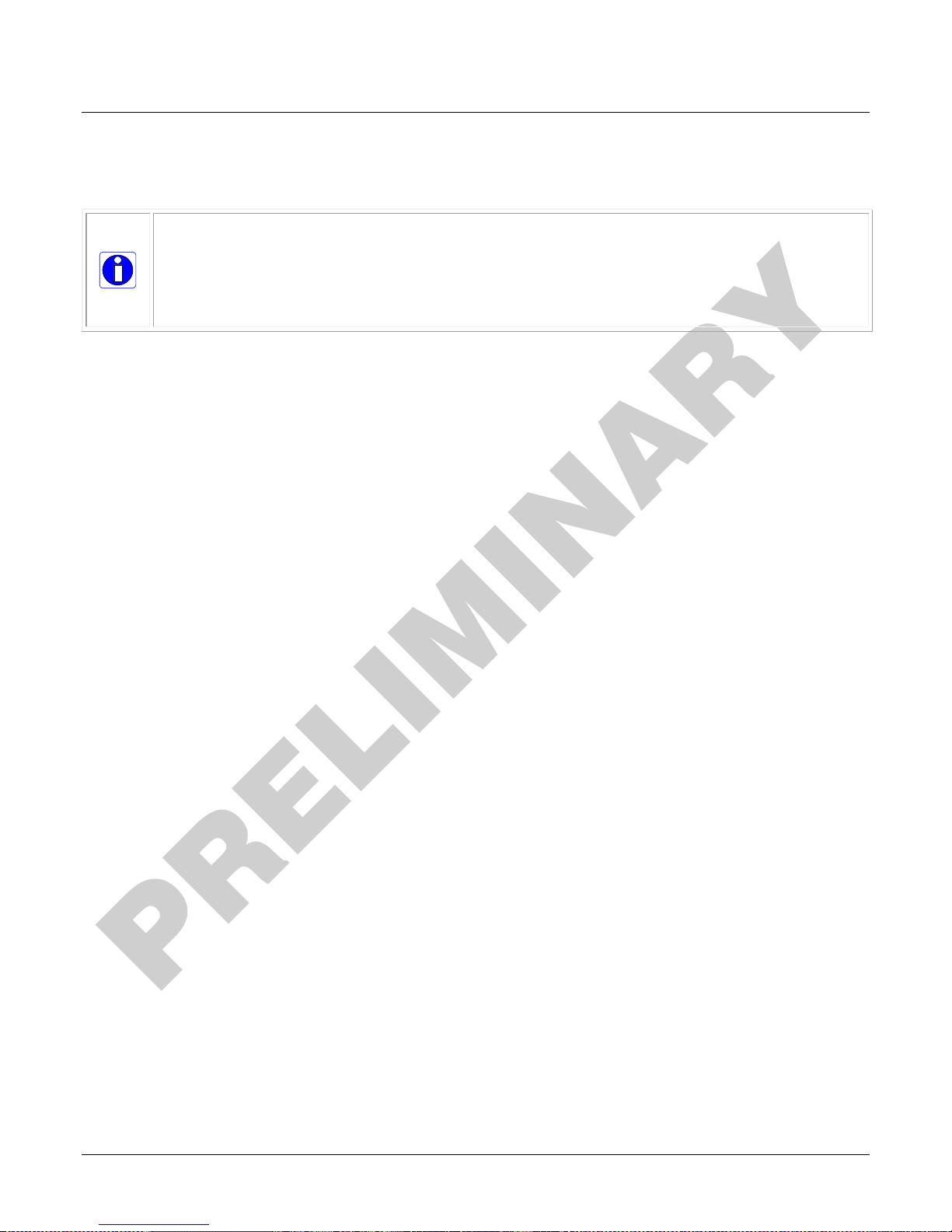
Identification Label
Linea CLHS cameras have an identification label applied to the back side, with the following information:
• Model Part number
• Serial number
• 2D Barcode
• CE and FCC logo
• “Made in Canada” Statement
44 • Technical Specifications Linea CLHS Series Camera
Page 47
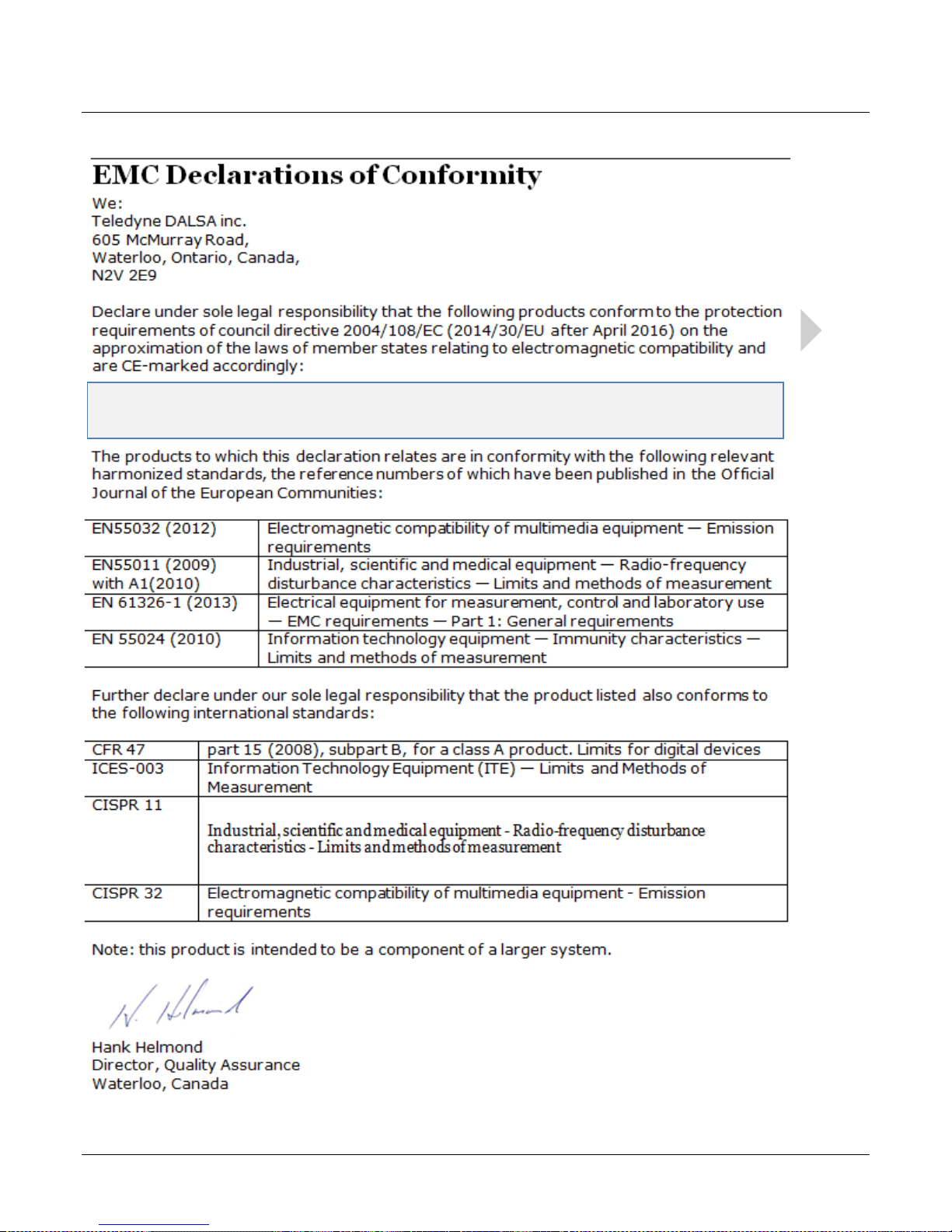
EMC Declarations of Conformity
Please note: conformity testing for the Linea CLHS cameras will be complete
in early 2017
Linea CLHS Series Camera Technical Specifications • 45
Page 48

Additional Reference
Information
Optical Considerations
This section provides an overview to illumination, light sources, filters, lens modeling, and lens
magnification. Each of these components contribute to the successful design of an imaging
solution.
Illumination
The amount and wavelengths of light required to capture useful images depend on the particular
application. Factors include the nature, speed, and spectral characteristics of objects being imaged,
exposure times, light source characteristics, environmental and acquisition system specifics, and
more. The Teledyne DALSA Web site, http://www.teledynedalsa.com/
this potentially complicated issue. Click on Knowledge Center and then select Application Notes and
Technology Primers. Review the sections of interest.
, provides an introduction to
It is often more important to consider exposure than illumination. The total amount of energy
(which is related to the total number of photons reaching the sensor) is more important than the
rate at which it arrives. For example, 5 µJ/cm
just the same as exposing an intensity of 5 W/cm
2
can be achieved by exposing 5 mW/cm2 for 1 ms
2
for 1 µs.
Light Sources
Keep these guidelines in mind when selecting and setting up light source:
• LED light sources are relatively inexpensive, provide a uniform field, and longer life span
compared to other light sources. However, they also require a camera with excellent sensitivity.
• Halogen light sources generally provide very little blue relative to infrared light (IR).
• Fiber-optic light distribution systems generally transmit very little blue relative to IR.
• Some light sources age such that over their life span they produce less light. This aging may
not be uniform—a light source may produce progressively less light in some areas of the
spectrum but not others.
46 • Additional Reference Information Linea CLHS Series Camera
Page 49
h
hm'
=
OD
fm'
=
OD
f
h
h ''
=
OD
mm
m
m 45
100
10
=
µ
µ
)450.0(450 mmmOD =
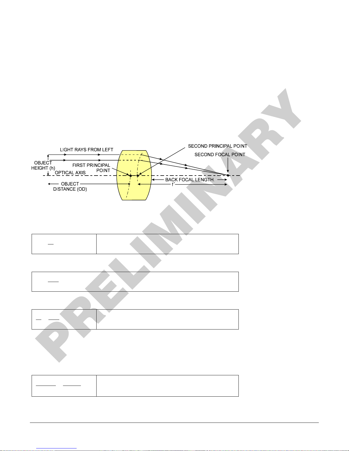
Lens Modeling
Any lens surrounded by air can be modeled for camera purposes using three primary points: the
first and second principal points and the second focal point. The primary points for a lens should be
available from the lens data sheet or from the lens manufacturer. Primed quantities denote
characteristics of the image side of the lens. That is, h is the object height and h′ is the image
height.
The focal point is the point at which the image of an infinitely distant object is brought to focus.
The effective focal length (f′) is the distance from the second principal point to the second focal
point. The back focal length (BFL) is the distance from the image side of the lens surface to the
second focal point. The object distance (OD) is the distance from the first principal point to the
object.
Primary Points in a Lens System
Magnification and Resolution
The magnification of a lens is the ratio of the image size to the object size:
Where m is the magnification, h’ is the image height (pixel
size) and h is the object height (desired object resolution
size).
By similar triangles, the magnification is alternatively given by:
These equations can be combined to give their most useful form:
This is the governing equation for many object and image
plane parameters.
Example: An acquisition system has a 512 x 512 element, 10µm pixel pitch area scan camera, a lens
with an effective focal length of 45mm, and requires that 100µm in the object space correspond to
each pixel in the image sensor. Using the preceding equation, the object distance must be 450mm
(0.450m).
Linea CLHS Series Camera Additional Reference Information • 47
Page 50
Sensor Handling Instructions
This section reviews proper procedures for handling, cleaning, or storing the camera. Specifically
the camera sensor needs to be kept clean and away from static discharge to maintain design
performance.
Electrostatic Discharge and the Sensor
Cameras sensors containing integrated electronics are susceptible to damage from electrostatic
discharge (ESD).
Electrostatic charge introduced to the sensor window surface can induce charge buildup on the
underside of the window that cannot be readily dissipated by the dry nitrogen gas in the sensor
package cavity. With charge buildup, problems such as higher image lag or a highly non-uniform
response may occur. The charge normally dissipates within 24 hours and the sensor returns to
normal operation.
Important: Charge buildup will affect the camera’s flat-field correction calibration. To avoid an
erroneous calibration, ensure that you perform flat-field correction only after a charge buildup has
dissipated over 24 hours.
Protecting Against Dust, Oil and Scratches
The sensor window is part of the optical path and should be handled like other optical components,
with extreme care.
Dust can obscure pixels, producing dark patches on the sensor response. Dust is most visible when
the illumination is collimated. The dark patches shift position as the angle of illumination changes.
Dust is normally not visible when the sensor is positioned at the exit port of an integrating sphere,
where the illumination is diffuse.
Dust can normally be removed by blowing the window surface using a compressed air blower,
unless the dust particles are being held by an electrostatic charge, in which case either an ionized
air blower or wet cleaning is necessary.
Oil is usually introduced during handling. Touching the surface of the window barehanded will leave
oily residues. Using rubber finger cots and rubber gloves can prevent oil contamination. However,
the friction between the rubber and the window may produce electrostatic charge that may
damage the sensor. To avoid ESD damage and to avoid introducing oily residues, avoid touching
the sensor.
Scratches can be caused by improper handling, cleaning or storage of the camera. When handling
or storing the camera without a lens, always install the protective cap. Scratches diffract incident
illumination. When exposed to uniform illumination, a sensor with a scratched window will normally
have brighter pixels adjacent to darker pixels. The location of these pixels changes with the angle
of illumination.
48 • Additional Reference Information Linea CLHS Series Camera
Page 51
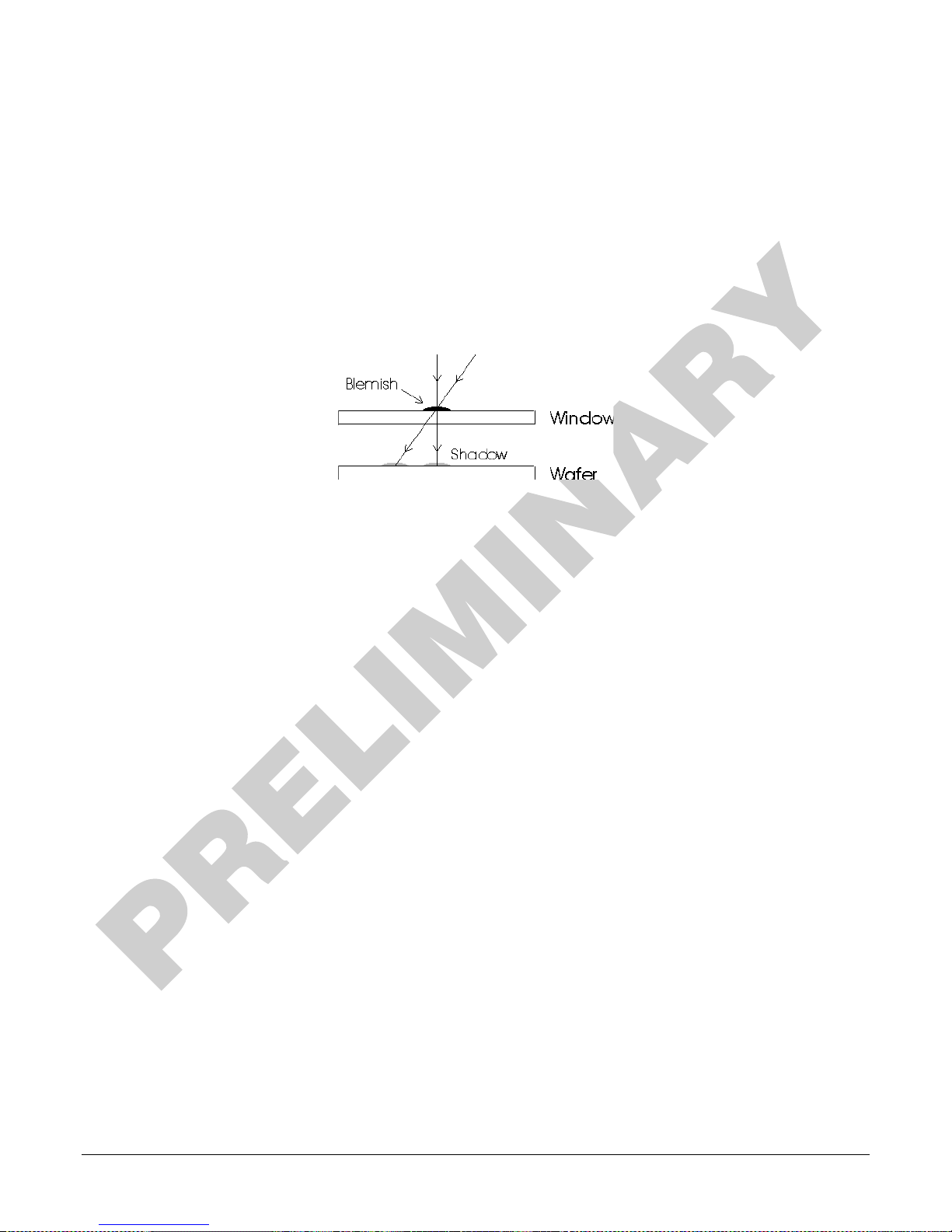
An important note on window blemishes
When flat field correction is performed, window cleanliness is paramount. The figure below shows
an example of what can happen if a blemish is present on the sensor window when flat field
correction is performed. The blemish will cast a shadow on the wafer. FFC will compensate for this
shadow by increasing the gain. Essentially FFC will create a white spot to compensate for the dark
spot (shadow). As long as the angle of the incident light remains unchanged then FFC works well.
However when the angle of incidence changes significantly (i.e. when a lens is added) then the
shadow will shift and FFC will makes things worse by not correcting the new shadow (dark spot)
and overcorrecting where the shadow used to be (white spot). While the dark spot can be
potentially cleaned, the white spot is an FFC artifact that can only be corrected by another FFC
calibration.
Cleaning the Sensor Window
Even with careful handling, the sensor window may need cleaning. The following steps describe
various cleaning techniques to clean minor dust particles to accidental finger touches.
• Use compressed air to blow off loose particles. This step alone is usually sufficient to clean the
sensor window. Avoid moving or shaking the compressed air container and use short bursts of
air while moving the camera in the air stream. Agitating the container will cause condensation
to form in the air stream. Long air bursts will chill the sensor window causing more
condensation. Condensation, even when left to dry naturally, will deposit more particles on the
sensor.
• When compressed air cannot clean the sensor, Dalsa recommends using lint-free ESD-safe
cloth wipers that do not contain particles that can scratch the window. The Anticon Gold 9”x 9”
wiper made by Milliken is both ESD safe and suitable for class 100 environments. Another ESD
acceptable wiper is the TX4025 from Texwipe.
• An alternative to ESD-safe cloth wipers is Transplex swabs that have desirable ESD properties.
There are several varieties available from Texwipe. Do not use regular cotton swabs, since
these can introduce static charge to the window surface.
• Wipe the window carefully and slowly when using these products.
Linea CLHS Series Camera Additional Reference Information • 49
Page 52

Appendix A: GenICam
Commands
This appendix lists the available GenICam camera features. Access these features using the
CamExpert interface.
Parameters in gray are read only, either always or due to another parameter being disabled.
Parameters in black are user set in CamExpert or programmable via an imaging application.
Features listed in the description table but tagged as Invisible are typically reserved for Teledyne
DALSA Support or third party software usage, and not typically required by end user applications.
Additionally the Standard column will indicate which parameter is a member of the custom DALSA
Features Naming Convention (denoted by DFNC), versus the GenICam Standard Features Naming
Convention (SFNC not shown).
Camera Information Category
Camera information can be retrieved via a controlling application. Parameters such as camera
model, firmware version, etc. are read to uniquely identify the connected device. These features
are typically read-only. GenICam applications retrieve this information to identify the camera along
with its characteristics.
The Camera Information Category groups information specific to the individual camera. In this
category the numbers of features shown are identical whether the view is Beginner, Expert, or
Guru. Features listed in the description table but tagged as Invisible are usually for Teledyne
DALSA or third party software usage—not typically needed by end user applications.
Camera Information Feature Descriptions
The following table describes these parameters along with their view attribute.
50 • Appendix A: GenICam Commands Linea CLHS Series Camera
Page 53
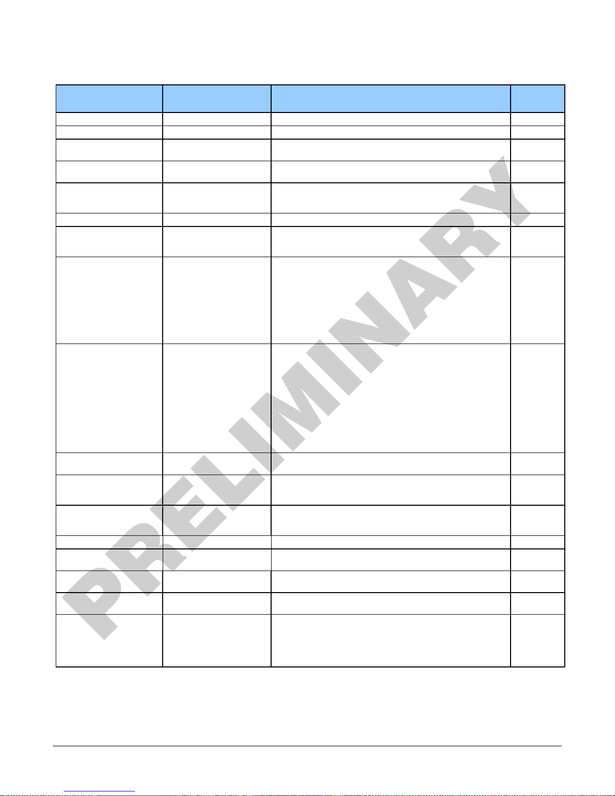
Display Name Feature & Values Description Standard
& View
Vendor DeviceVendorName Displays the device vendor name. (RO) Beginner
Model DeviceModelName Displays the device model name. (RO) Beginner
CCI Version DeviceVersion Displays the device version. This tag will also highlight if the
FPGA Version DeviceManufacturerInfo This feature provides extended manufacturer information about
Microcode Version DeviceFirmwareVersion Displays the currently loaded firmware version number.
Serial Number DeviceID Displays the device’s factory set camera serial number. (RO) Beginner
Device User ID DeviceUserID Feature to store a user-programmable identifier of up to 15
Power-on User Set UserSetDefaultSelector Selects the camera configuration set to load and make active on
Factory Factory Load factory default feature settings.
UserSet1
to
UserSet8
User Set Selector UserSetSelector Selects the camera configuration set to load feature settings
Factory Set Factory Select the default camera feature settings saved by the factory.
UserSet1 Select the user defined configuration (UserSet1 to UserSet8) as
firmware is a beta or custom design. (RO)
the device, such as the firmware design type. (RO)
Firmware files have a unique number and have the .cbf file
extension. (RO)
characters. The default factory setting is the camera serial
number. (RW)
camera power-up or reset. The camera configuration sets are
stored in camera non-volatile me mory. (RW)
the Power-up Configuration.
from or save current feature settings to. The Factory set
contains default camera feature settings. User camera
configuration sets contain features settings previously saved by
the user. (RW)
Beginner
Beginner
Beginner
Beginner
Beginner
Beginner
User Set 1
to
User Set 8
Load User Set UserSetLoad Loads the camera configuration set specified by the User Set
Save User Set UserSetSave Saves the current camera configuration to the user set specified
Power-on Status deviceBISTStatus Return the status of the device Built-In Self Test (BIST).
Device Temperature DeviceTemperature Displays the device temperature in degrees Celsius Beginner
Refresh Temperature refreshTemperature Gets the current device temperature and refreshes the
Input Voltage deviceInputVoltage Displays the device power input voltage. DFNC
Refresh Voltage refreshVoltage Gets the current device input voltage and refreshes the
LED Color deviceLEDColor Displays the current status LED state. DFNC
Good Green Camera status OK.
Blink Green BlinkGreen Camera is currently powerering-up or busy.
BIST Error Red Camera built-in self-test failure.
UserSet1 Select the User Defined Configuration space (UserSet1 to
UserSet8) to save to or load from features settings previously
saved by the user.
Selector feature, to the camera and makes it active. (W)
by the User Set Selector feature. The user sets are located on
the camera in non-volatile memory. (W)
Possible return values are device-specific: refer to Appendix C:
Error and Warning Messages.
DeviceTemperature value.
deviceInputVoltage value.
Beginner
Beginner
DFNC
Beginner
DFNC
Beginner
Beginner
DFNC
Beginner
Beginner
Linea CLHS Series Camera Appendix A: GenICam Commands • 51
Page 54
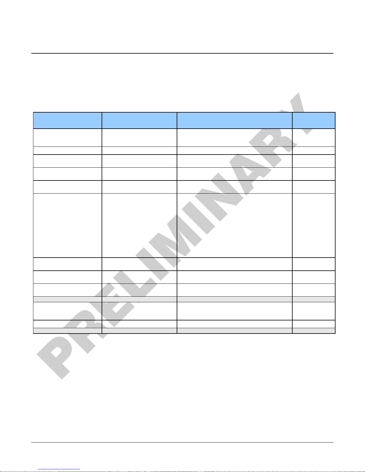
Camera Control Category
The camera controls, as shown by CamExpert, groups sensor specific features. This group includes
controls for line rate and exposure time.
Camera Control Feature Descriptions
The following table describes these features along with their view attribute:
Display Name Feature & Values Description Standard
& View
Sensor Color Type sensorColorType Defines the camera sensor color type. < RO > Beginner
Monochrome Monochrome Sensor color type is monochrome.
Internal Line Rate Acquisit ionLineRate Specifies the camera internal line rate, in Hz. Beginner
Measured Line Rate measureLineRate Displays the line rate provided to the camera by
Measured CC1 measureCC1Rate Displays the CC1 signal rate provided to the
Refresh measured line rate refreshMeasureLineRate Updates the measureLineRate value.
Exposure Time Source ExposureMode Sets the operation mode for the camera’s
Timed Timed The exposure duration time is set using the
Trigger Width TriggerWidth Uses the width of the trigger signal pulse to control
Exposure Time ExposureTime Sets the exposure time (in microseconds) when the
Measured Exposure Time measureExposureTime Displays the exposure time used by the camera
Refresh Measured Exposure
Time
refreshMeasuredExposureTime Updates the measuredExposureTime value. DFNC
either internal or external source < RO >
camera. <RO>
exposure.
Exposure Time feature and the exposure starts
with a LineStart event.
the exposure duration. Use the Trigger Activation
feature to set the polarity of the trigger. The
Trigger Width setting is applicable when the
LineStart trigger is enabled and a signal is selected
as trigger source.
Exposure Mode feature is set to Timed.
sensor.
DFNC
DFNC
Beginner
DFNC
Beginner
DFNC
Beginner
Beginner
Beginner
DFNC
Beginner
Beginner
Offset BlackLevel Analog black level (o ffset) in DN. Controls the black
Gain Gain Sets the digital gain applied to the image. Beginner
52 • Appendix A: GenICam Commands Linea CLHS Series Camera
level as an ab solute physical value. This represents
Beginner
a DC offset applied to the video signal.
Page 55
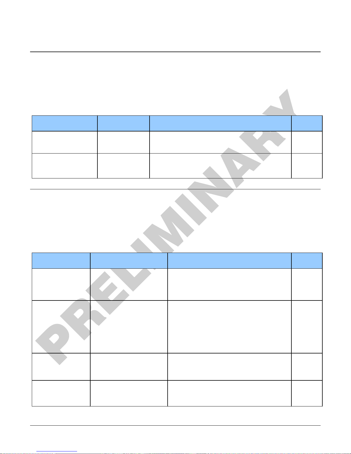
Beginner
DFNC
Off
Off
Flat field correction is disabled.
On
On
Flat field correction is enabled.
2048
Lines_2048
Average 2048 lines.
4096
Lines_4096
Average 4096 lines.
I/O Control Category
The camera’s I/O controls, as shown by CamExpert, group features used to configure external
inputs and acquisition actions based on those inputs, plus camera output signals to other devices.
I/O Control Feature Descriptions
The following table describes these features along with their view attribute and minimum camera
firmware version required:
Display Name Feature & Values Description Standard
& View
Trigger Selector TriggerSelector Displays the type of trigger to configure with the various
Trigger features. <RO>
LineStart LineStart Selects a trigger starting the capture of a single line.
Trigger Mode TriggerMode Controls the enable state of the selected trigger.
Off Off The selected trigger is turned off.
On On The selected trigger is turned active.
Beginner
Flat Field Category
The camera’s Flat Field controls, as shown by CamExpert, group features used to calibrate the
camera’s flat field correction coefficients. Parameters in black are user set in CamExpert or
programmable via an imaging application.
Flat Field Feature Descriptions
The following table describes these features along with their view attribute:
Display Name Feature & Values Description Standard
& View
Mode flatfieldCorrectionMode Sets the mode for flat field correction.
Initialize Initialize Reset all FPN coefficients to 0 and all flat field
coefficients to 1.
Calibration Algorithm flatfieldCorrectionAlgorithm Selects the algorithm to use for calibration of flat
field coefficients.
Basic Basic Direct calculation of coefficients based on average
line values and target value.
Low Pass Filter LowPass A low pass filter is first applied to the average line
values before calculating the coefficients. Use this
algorithm if the calibration target is not uniformly
white or it is not possible to defocus the image.
CalibrationTarget flatfieldCalibrationTarget Sets the target pixel value for the gain (PRNU)
calibration. Ranges are:
8-bit output: 0-255
12-bit output: 0-4095
CalibrationSampleSize flatfieldCalibrationSampleSize Sets the number of line to average during a flat
field calibration.
Beginner
DFNC
Beginner
DFNC
Beginner
DFNC
Beginner
Linea CLHS Series Camera Appendix A: GenICam Commands • 53
Page 56
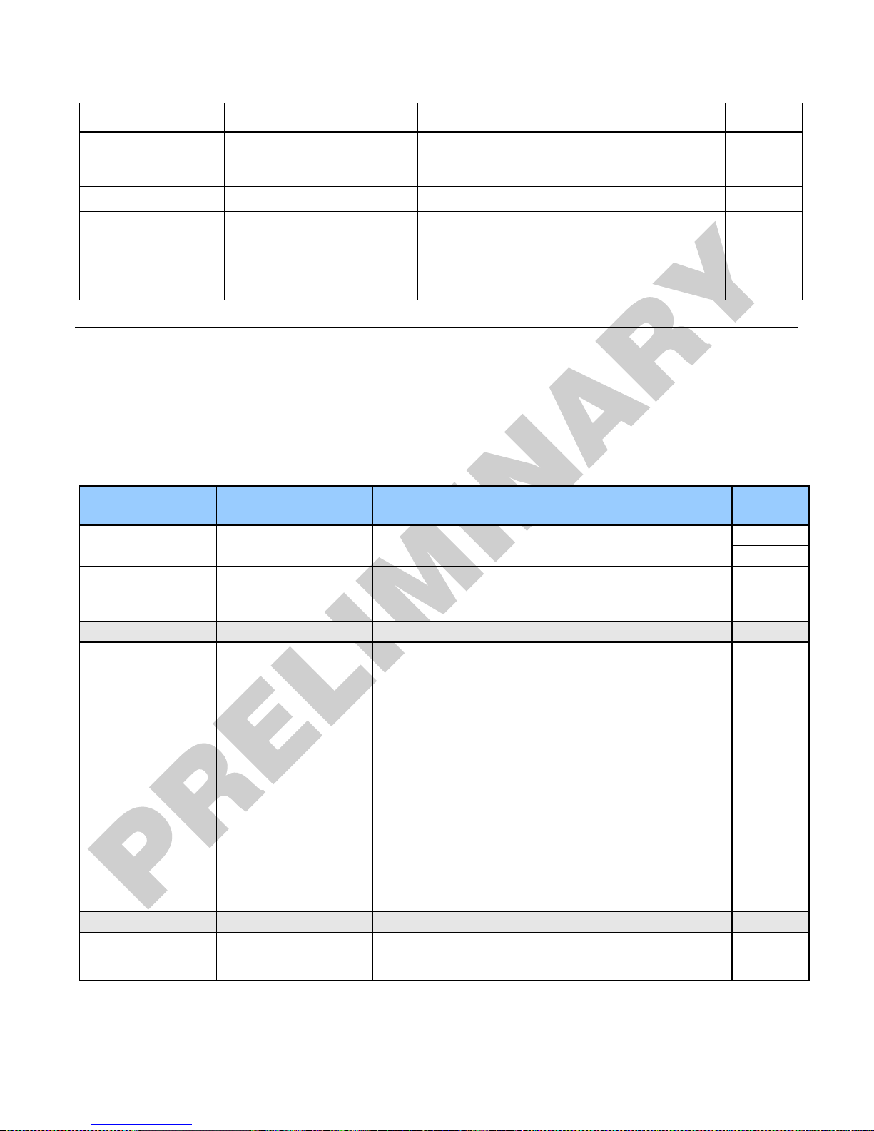
a flat field calibration will be performed
flat field calibration will be performed
Calibrate FPN
flatfieldCalibrationFPN
Initiates the FPN calibration process.
DFNC
Beginner
Calibrate PRNU Status
flatfieldCalibrationPRNUStatus
Returns the PRNU calibration status.
Good
Good
Calibration successful.
Time Out
ExsyncTimeOut
Calibration failed due to time out.
Too Many Outliers
TooManyOutliers
Calibration failed because the image is too noisy.
Beginner
Beginner
ROI Offset X flatfieldCalibrationROIOffset Set the starting point of a region of interest where
ROI Width flatfieldCalibrationROIWidth Sets the width of the region on interest where a
Calibrate PRNU flatfieldCalibrationPRNU Initiates the PRNU or Flatfield process.
Clipping Clipping Coefficients are clipped to minimum or maximum
value.
DFNC
Beginner
DFNC
Beginner
Beginner
DFNC
DFNC
Beginner
Image Format Control Category
The camera’s Image Format controls, as shown by CamExpert, group parameters used to configure
camera pixel format, image cropping, and the binning function. Additionally, a feature control to
select and output a camera internal test image simplifies qualifying a camera setup without a lens.
Image Format Control Feature Description
The following table describes these features along with their view attribute:
Display Name Feature & Values Description Standard
& View
Pixel Coding PixelCoding Output image pixel coding format of the sensor. <RO>
Mono Mono Monochrome format.
Pixel Color Filter PixelColorFilter Indicates the type of color filter applied to the image.
None None No filter applied on the sensor.
Test Pattern TestImageSelector Selects the type of test image output by the camera.
Off Off Image is from the camera sensor.
Ramp Ramp Image is filled horizontally with an image that goes from
Alternating A5 Alternating values. For 12-bit output, pixel values alternate
Fixed Pattern Each_Tap_Fixed 8 pixel cycling pattern. For 12-bit output, the pattern is
Fixed Value
1381(86)
Fixed Value 32(2) All_1 Fixed Grey Value. For 12-bit output: pixel value = 32
Vertical Binning BinningVertical Number of vertical photo-sensitive cells to combine
All_1365 Fixed Grey Value. For 12-bit output: pixel value = 1381
<RO>
the darkest possible value to the brightest.
between 1381 (0x565) and 2746 (0xABA). For 8-bit
output, pixel values alternate between 86 (0x56) and 172
(0xAC).
0x120|0x020|0x130|0x030|0x140|0x040|0x150|0x050.
For 8-bit output, the pattern is
0x12|0x02|0x13|0x03|0x14|0x04|0x15|0x05.
(0x565). For 8-bit output: pixel value = 86 (0x56).
(0x20). For 8-bit output: pixel value = 2 (0x2).
together. This increases the intensity of the pixels but
reduces the vertical resolution of the image.
Beginner
Beginner
54 • Appendix A: GenICam Commands Linea CLHS Series Camera
Page 57
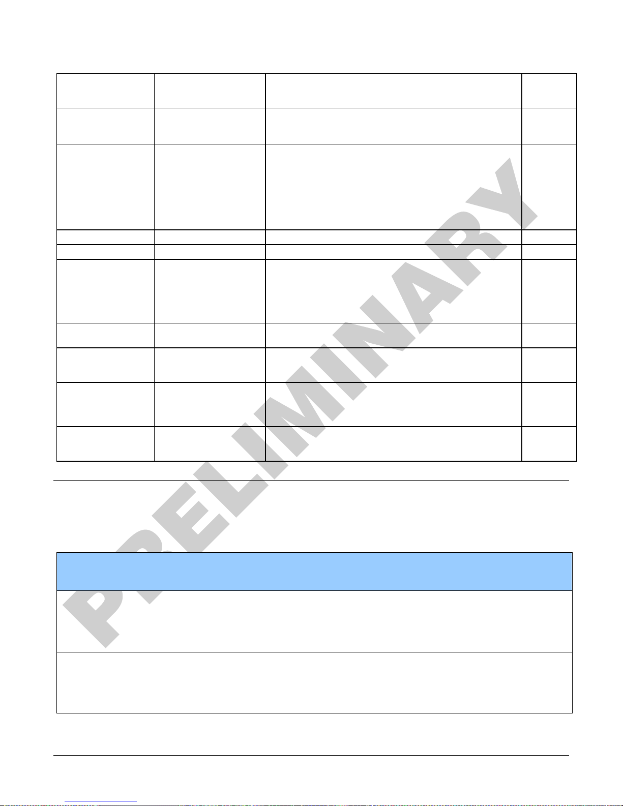
Off
Off
Video output in normal order
On
On
Video output in a reverse order
Beginner
DFNC
DFNC
DFNC
Horizontal Binning BinningHorizontal Number of horizontal photo-sensitive cells to combine
together. This increases the intensity of the pixels but
reduces the horizontal resolution.
Line Mirroring ReverseX Horizontal image flip function.
Pixel Format PixelFormat Output image pixel coding format of the sensor..
Mono8 Mono8 Mono8: Monochrome 8-Bit.
Note: Camera Link Full configurations support this format
only.
Mono12 Mono12 Mono12: Monochrome 12-Bit
Note: Camera Link Base or Medium configurations can use
this format.
Width Width Width of the Image provided by the device (in pixels).
Height Height Height of the Image provided by the device (in lines).
Multiple AOI Mode multipleAOIMode Enable the Multiple AOI (Area of Interest) per image
feature. The AOI Count is set by the Multiple AOI Count
feature.
Off Off Single AOI per image.
Active Active The AOI per image feature is active.
AOI Count multipleAOICount Specifies the number of AOIs (Area of Interest) available
for the X axis.
AOI Selector multipleAOISelector Select an AOI (Area of Interest) when Multiple AOI Mode is
enabled. Selector range is from 1 to the MultipleAOICount
value.
AOI Offset X multipleAOIOffsetX Horizontal offset (in pixels) from the origin to the selected
AOI (Area of Interest). The offset is set as a multiple of 8
or 10 (deca mode) + 1. The maximum offset is the image
width – 40.
AOI Width multipleAOIWidth Width of the selected AOI (Area of Interest) provided by
the device (in pixels). The minimum region width is 40
pixels and must be a multiple of 8 or 10 (deca mode).
Beginner
Beginner
Beginner
Beginner
DFNC
Expert
Expert
DFNC
Expert
Expert
Expert
Transport Layer Category
The camera’s Transport Layer, as shown by CamExpert, groups features for camera configuration.
Transport Layer Feature Descriptions
Display Name Feature Description Device
XML Major Version DeviceManifestXMLMajorVersion
XML Minor Version DeviceManifestXMLMinorVersion
Linea CLHS Series Camera Appendix A: GenICam Commands • 55
Together with
DeviceManifestXMLMinorVersion
specifies the GenICam feature
description XML
file version (RO)
Together with
DeviceManifestXMLMajorVersion
specifies the GenICam feature
description XML
file version (RO)
Version
& View
1.00
Beginner
DFNC
1.00
Beginner
DFNC
Page 58

Refresh GenCP
refreshGenCPStatus Press to return the current status of the
Status
Last GenCP Status genCPStatus
CLHS Discovery
clhsDiscovery Selects between CLHS discovery mode
Discovery Disabled
Discovery Enabled
Next CLHS Device
clhsNext DeviceConfig When the camera is next powered up,
Configuration
One cable seven
lanes
One cable four lanes
One cable one lanes
Two cable seven
lanes
Two cable four lanes
Two cable one lanes
CLHS 8b/10b
clhsErrorCountSelector Selects the error count that the
Receive Error Count
selector
Data 2 Receive Error
Count
Control/Data1
Receive Error Count
CLHS 8b/10b
clhsError Count CLHS error count value for the selected
Receive Error Count
Refresh CLHS
clhsError CountRefresh When pressed, the error count is
8b/10b Receive Error
Count
Reset Receive Error
clhsErrorCountReset When pressed, the error count is rest to
Count
GenCP
If a feature read or write fails then
Sapera only
returns that it fails – read this feature to
get the
actual reason for the failure
Returns the last error
Reading this feature clears it
which automatically determines the
configuration of the CLHS interface
when enabled. When disabled, the
frame grabber needs to have the
configuration set by the user
CLHS transmitters are enabled
immediately on power up
CLHS transmitters enable after sending
Acquisition start
the specified CLHS lane configuration
will be set for the camera.
following three features apply to
data/control lanes (RO)
updated
zero
1.00
Beginner
1.00
Beginner
DFNC
1.00
Guru
DFNC
1.00
Guru
DFNC
1.00
Guru
DFNC
1.00
Guru
DFNC
1.00
Guru
DFNC
1.00
Guru
DFNC
56 • Appendix A: GenICam Commands Linea CLHS Series Camera
Page 59
Invisible
Invisible
Invisible
Invisible
Guru
FPGA Code
FPGA_Code
Upload new FPGA to the camera which will
execute on the next camera reboot cycle.
execute on the next camera reboot cycle.
execute on the next camera reboot cycle.
execute on the next camera reboot cycle.
Device Streaming Registers
Start – End Command Requirements
Important: Every start command must have a corresponding end command. If not the
camera can be in an unpredictable state. This pertains to
DeviceRegistersStreamingStart, DeviceRegistersStreamingEnd,
DeviceFeaturePersistenceStart, and DeviceFeaturePersistenceEnd.
Display Name Feature & Values Description Standard
& View
Device Registers
Streaming Start
Device Registers
Streaming End
Device Feature
Streaming Start
Device Feature
Streaming End
Register Check DeviceRegistersCheck Performs an explicit register set validation for
Registers Va lid DeviceRegistersValid States if the current register set is valid and
DeviceRegistersStreamingStart Announces the start of registers streaming without
immediate checking for consistency.
DeviceRegistersStreamingEnd Announces end of registers streaming and performs
validation for registers consistency before activating
them.
DeviceFeaturePersistenceStart Announces the start of feature streaming without
immediate checking for consistency.
DeviceFeaturePersistenceEnd Announces end of feature streaming and performs
validation for feature consistency before activating
them.
consistency.
consistent.
Invisible
Invisible
File Access Control Category
The File Access control in CamExpert allows the user to quickly upload various data files to the
connected camera. The supported data files are for camera firmware updates and Flat Field
coefficients.
Features listed in the description table but tagged as Invisible are usually for Teledyne DALSA or
third party software usage—not typically needed by end user applications.
File Access Control Feature Descriptions
Display Name Feature & Values Description Standard
& View
File Selector FileSelector Selects the file to access. The file types which
are accessible are device-dependent.
MicroCode MicroCode Upload new micro codeto the camera which will
CCI CCI Upload new CCI to the camera which will
XML XML Upload new XML to the camera which will
Linea CLHS Series Camera Appendix A: GenICam Commands • 57
Page 60

access.
flatfield to access.
to access.
customer support.
Guru
User Set User_Set Use UserSetSelector to specify which user set to
Flat Field Flat_Field Use UserSetSelector to specify which user
User FPN User_FPN Use UserSetSelector to specify which user FPN
CameraData Camera_Data Download camera information and send for
File Operation Selector FileOperationSelector Selects the target operation for the selected file
in the device. This operation is executed when
the File Operation Execute feature is called.
Open Open Select the Open operation - executed by
FileOperationExecute.
Close Close Select the Close operation - executed by
FileOperationExecute
Read Read Select the Read operation - executed by
FileOperationExecute.
Write Write Select the Write operation - executed by
FileOperationExecute.
Delete Delete Select the Delete operation - executed by
FileOperationExecute.
File Operation Execute FileOperationExecute Executes the operation selected by File
Operation Selector on the selected file.
File Open Mode FileOpenMode Selects the access mode used to open a file on
the device.
Read Read Select READ only open mode
Write Write Select WRITE only open mode
File Access Buffer FileAccessBuffer Defines the intermediate access buffer that
allows the exchange of data between the device
file storage and the application.
File Access Offset FileAccessOffset Controls the mapping offset between the device
file storage and the file access buffer.
File Access Length FileAccessLength Controls the mapping length between the device
file storage and the file access buffer.
File Operation Status FileOperationStatus Displays the file operation execution status.
(RO)
Success Success The last file operation has completed
successfully.
Failure Failure The last file operation has completed
unsuccessfully for an unknown reason.
File Unavailable FileUnavailable The last file operation has completed
unsuccessfully because the file is currently
unavailable.
File Invalid FileInvalid The last file operation has completed
unsuccessfully because the selected file in not
present in this camera model.
File Operation Result FileOperationResult Displays the file operation result. For Read or
Write operations, the number of successfully
read/written bytes is returned. (RO)
File Size FileSize Represents the size of the selected file in bytes.
Guru
Guru
Guru
Guru
Guru
Guru
Guru
Guru
58 • Appendix A: GenICam Commands Linea CLHS Series Camera
Page 61
I2C error
1
Unable to configure fpga
10
EXT_SRAM Failure
1000
ECHO_BACK Failure
1,0000
FLASH_TIMEOUT
10,0000
FLASH_ERROR
100,0000
NO_FPGA_Code
1000,0000
NO_COMMON_SETTINGS
1,0000,0000
NO_FACTORY_SETTINGS
10,0000,0000
NO_USER_SETTINGS
100,0000,0000
NO_FLAT_FIELD Corrections
1000,0000,0000
NO MISC corrections
1,0000,0000,0000
NO_FPN Correction
10,0000,0000,0000
NO_FPN Correction
100,0000,0000,0000
NO_FEED Through Correction
1,0000,0000,0000,0000
NO_LINEARITY Correction
10,0000,0000,0000,0000
SYNC_ERROR
100,0000,0000,0000,0000
OVER_TEMPERATURE
1000,0000,0000,0000,0000
SPI Failure
1,0000,0000,0000,0000,0000
NO_USER_FPN
10,0000,0000,0000,0000,0000
PLL_LOCK_FAILED
100,0000,0000,0000,0000,0000
INVALID_CCI
1000,0000,0000,0000,0000,0000
No LUT
1,0000,0000,0000,0000,0000,0000
Incompatible FPGA code
10,0000,0000,0000,0000,0000,0000
Appendix C: Error and Warning
Messages
BiST: Built in Self Test
The BiST error flags are binary flags with each bit being independent from each other. The
message from the BiST should be “Good” meaning everything is functioning correctly but if a
hardware failure does occur in the camera one or more these flags could be set. Any of these
errors will result in the status light turning red.
Definition BiST Flag
Unable to configure fpga 100
NO_PRNU Correction 1000,0000,0000,0000
Linea CLHS Series Camera • 59
Page 62
0X8002
Invalid Parameter
0xC01C
CPA_TOO_MANY_OUTLIERS
0x401E
USER_FPN_CLIPPING
0x401F
FLAT_FIELD_CLIPPING
Operational Error Codes
Code Description
60 • Appendix C: Error and Warning Messages Linea CLHS Series Camera
Page 63
00
Preliminary release.
December 12, 2016
Document Revision History
Revision Description Date
Linea CLHS Series Camera • 61
 Loading...