

Page 1
Installation and Use – Please store this document securely!
Security advice
Please read this manual carefully and completely – it contains useful and important information on the function, maintenance, placement and
installation of this detector. Reliable operation can only be guaranteed if the instructions are followed correctly.
Please check the installation location carefully in advance in case there are any electrical installations behind the wall or above the ceiling!
In case of alarm a very loud sound is emitted. Do not switch the unit on in close proximity to anybodies ears! Keep away from children! This
smoke detector is a photo electric sensor with integrated relays to connect to any alarm control system such as the RMS. When smoke is
detected a loud siren is sounded and the relay is activated.
Smoke detection works using scattered light technology which is highly sensitive to any fire especially smouldering fire. The integrated heat
sensor activates the alarm at approximately 70~85°C.
An automatic self test is performed regularly and any malfunction is shown by the integrated LED.
Supplied Contents
Smoke detector, 2 screws, mounting plate, ~4m cable, this manual
Technical Data
Operating voltage: 12 V DC or AC +/-15% Typical current: 2mA, Alarm current approx. 25mA
Operating temperature: 0°C ~ +55°C Humidity: 25% ~ 75% relative humidity, non condensing, for indoor use
Smoke sensor: scattered light principle Sensitivity: m= 0,05…0,07dB/m (EN 54-7)
Heat sensor alarm 70°C~85°C Alarm siren ~ 85dB(A) / 3m
Life time: 10 years maximum Relay: max. 1A@120VAC, max. 2A@24VDC
Conformity: EN54-7 and prEN ISO 12239 Cable: ~ 4m
Weight: 0.1kg Dimensions: ∅ 12 x 4cm
Placement
The Smoke sensor should be mounted on the ceiling, if possible, in the centre of the ceiling. A minimum distance of 60cm to any wall or
other equipment should be kept. In rooms with non horizontal ceilings the sensor should be placed approximately 1m off the highest point.
In long corridors or rooms the smoke sensor should not be more than 4m away from any wall and should not be spaced more than 8m
apart .
As a rule of thumb: One smoke detector can cover a room of 50m³ approx.
The following locations are not suitable and should not be used:
Near a wall, window, door, heating or ventilation device, in stair cases or in any place with constant air flow.
Any area where the temperature often falls below 4°C or increases over +40°C
In any area with high relative humidity, for instance bathrooms
In small or poorly ventilated garages, kitchens or similar, otherwise false alarms may be caused by exhaust gases and steam
Any place where the self test LED button cannot be reached
Close to fluorescent lamps (keep a minimum distance of 50cm!) or close to cables or any area with a high degree of electrical interference
In any rooms or areas with a high degree of dust or dirt, otherwise false alarms can be caused (i.e. workshops, barns)
Installation
1. This smoke detector should only be powered from an appropriate regulated power supply. Follow your local installation guidelines and legal
instructions! Protect the smoke detector from dirt and dust!
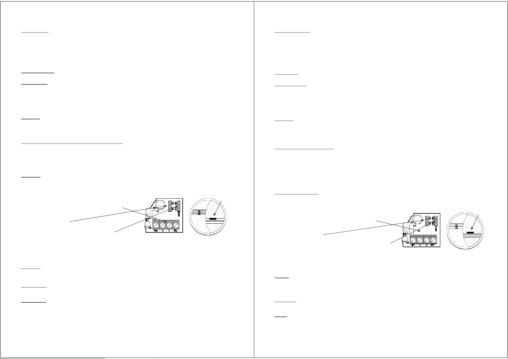
2. Drill a hole for the cable through the back of the detector. Guide the cable through the hole and fix it to the mounting plate or ceiling.
Connect the cable to your alarm system / the RMS as follows:
The blue contact strip can be pulled off the PCB for easy connection of the cables.
U, U Power supply (11 – 15 Volt AC or DC)
REL, REL Output relay contacts
The jumper contacts (K4) sets the detector function as NO (normally open
contact) or NC (normally closed contact).
The jumper contacts (K5) set the contact function of the relay:
K5=ON -> the alarm and the relay are activated for a short time until the supply voltage is interrupted. This helps to localize the detector that has
caused the alarm.
K5=OFF -> the alarm and relay is self reset as soon as the smoke density goes back to normal.
3. Finally, put the contact strip back on to the PCB. Put the cover back into its place and close it firmly so that both latches are engaged. Switch
on the supply voltage. Now, the detector should give one beep to indicate its operation state. Next, hold the LED test button down until a loud
pulsating warning tone is emitted and the relay is activated.
Operation
Under normal operation, every 40 seconds a self test is performed. This is indicated by a short LED flash. As soon as the sensor detects smoke
the alarm is activated (siren and relays). If K5 is set to OFF the alarm is reset as soon as the smoke density goes below the alarm level – the
detector is active again. To test the detector manually, hold down the test LED button until the alarm is sounded.
False Alarms
When an alarm is activated, check carefully for hidden fires. To reset the alarm, ventilate the room for a while and then switch off the supply
voltage (if K5 is set ON) for a short time. Use a vacuum cleaner to clean the detector.
Maintenance
Use a dust or vacuum cleaner to clean the detector every 6 months. The cover can be cleaned with a damp cloth. Do not use any strong
solvents. Do not paint the detector.
Test
button
with LED
Bedienungs- und Montageanleitung - Bitte sorgfältig aufbewahren!
Sicherheitshinweise
Bitte lesen Sie diese Anleitung vollständig durch – sie enthält wichtige Informationen über Funktionen, Montage, Platzierung und Pflege dieses
Produktes. Eine zuverlässige Frühwarnung bei Brand und Rauchentwicklung ist nur gegeben, wenn dieser Rauchmelder im Einklang mit dieser
Anweisung verwendet wird.
Überprüfen Sie die Montagestelle vor Bohrarbeiten auf unter Putz verlegte Leitungen.
Bei Alarm ertönt ein lauter pulsierender Warnton. Die Sirene ist laut! Nicht in direkter Ohrnähe einschalten. Halten Sie Kinder davon fern.
Der Rauchmelder hat einen foto-elektronischen Sensor und einen Relaisausgang zum Anschluss an den digitalen Eingang des RMS. Bei
Raucherfassung ertönt ein lauter Warnton und das eingebaute Relais wird aktiviert. Die Rauchentdeckung funktioniert nach dem Streulichtprinzip, das besonders schnell auf Schwelbrände reagiert. Der integrierte Hitzesensor löst Alarm bei Temperaturen über 70 – 85° C aus.
Eine automatische Selbstkontrolle wird regelmäßig durchgeführt und Störungen über die Leuchtdiode gemeldet.
Lieferumfang
Rauchmelder, 2 Schrauben, Montagewinkel, ~4m Anschlusskabel, diese Anleitung
Technische Daten
Betriebsspannung: 12 V DC oder AC +/-15% Ruhestrom: 2mA, Alarmstrom ca. 25mA
Temperaturbereich: 0~55°C, nur in geschlossenen Räumen Luftfeuchtigkeitsbereich 25~75% rel. Luftfeuchte, nicht kondensierend
Rauchsensor: Streulichtprinzip Empfindlichkeit: m= 0,05…0,07dB/m (EN 54-7)
Hitzesensor Alarmauslösung ca. 70°C-85°C Eingebaute Sirene ca. 85dB(A) / 3m
Lebensdauer: 10 Jahre maximal Relais: max. 1A@120VAC, max. 2A@24VDC
Erfüllt EN54-7 und prEN ISO 12239 Normen Kabel: ca. 4m
Gewicht: ca. 0,1kg Maße ca.: ∅ 12 x 4cm
Plazierung
Rauchmelder sollten an der Decke, möglichst in der Mitte des Raumes montiert werden. Ein Mindestabstand von 60 cm zu Wänden und
anderen Gegenständen sollten immer eingehalten werden. Bei Räumen mit Schräg-, Spitz- oder Giebeldecken, wo stehende Luft den
Rauchaufstieg verhindern kann, sollte der Rauchalarm ca. 1 Meter vom höchsten Punkt montiert werden.
In langen Gängen sollten Rauchmelder nicht mehr als 8m auseinander, nicht mehr als 4m vom Gangende und nicht mehr als 7m von jeder
Tür montiert werden.
Als Faustregel: Ein Rauchmelder kann einen Raum von ca. 50m³ (ohne Trennung) überwachen.
Folgende Stellen sind nicht geeignet:
An der Wand oder in der Nähe von Türen, Fenstern, Heizkörpern, Ventilatoren, in Treppenhäusern, etc., wo Luftzüge entstehenden Rauch
ablenken können.
In Bereichen, in denen die Temperatur des Öfteren unter 4°C fällt oder über 40°C steigt.
In Bereichen mit erhöhter Luftfeuchtigkeit, z.B. im Badezimmer.
In kleinen oder schlecht gelüfteten Garagen und Küchen, können Abgase und Dämpfe Fehlalarme auslösen.
An Stellen, an denen Sie den Rauchmelder zum Funktionstest schlecht erreichen.
In der Nähe von Leuchtstoffröhren (mindestens 50cm Abstand einhalten) oder stromführenden Leitungen oder in Bereichen, in denen ein
erhöhtes Niveau an „Elektrosmog“ herrscht.
In Bereichen, in denen starker Staub- oder Schmutzanfall die Funktion beeinträchtigt oder Fehlalarme auslösen könnten (z.B. Werkstätten
oder Scheunen).
Montage und Installation
Dieser Melder sollte nur an eine geeignete, geregelte Stromquelle angeschlossen werden. VDE und Bauvorschriften beachten. Vor Staub
schützen!
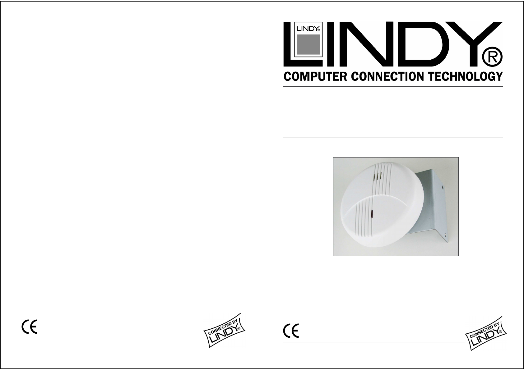
Bohren Sie gegebenenfalls ein Loch für die Kabeldurchführung durch das Gehäuse-Rückenteil. Ziehen Sie das Kabel durch das Loch und
befestigen Sie das Gehäuse-Rückenteil gegebenenfalls mit den mitgelieferten Schrauben an den Winkel.
Schließen Sie die Verdrahtung an der Alarmzentrale / RMS wie folgt an.
Die blaue Anschlussklemmleiste ist von der Platine trennbar (abziehen), um das
Anschließen zu erleichtern.
U,U Stromversorgung (11 – 15 Volt AC oder DC)
REL,REL Ausgangs-Relaiskontakte.
Durch die Stellung der Brücke K4 wird die Kontaktart auf NO (Schliesser)
bzw NC (Öffner) eingestellt.
Durch die Brücke K5 wird die Kontaktart der Relais eingestellt: Ist die Brücke K5 auf
„ON“ eingestellt, wird der Warnton und das Relais bis zu einer kurzen Unterbrechung
der Stromzufuhr aktiviert. Dies ist für die Lokalisierung der Alarmquelle nützlich. Ist die Brücke K5 auf „OFF“ eingestellt, so stellen sich der
Warnton und das Relais automatisch zurück, wenn sich die Rauchdichte wieder abbaut.
Schließen Sie die Anschlussklemmleiste wieder auf der der Platine an. Drücken Sie das Vorderteil auf das Rückenteil des Gehäuses, so dass
beide Befestigungslaschen einrasten. Schalten Sie die Stromversorgung ein. Der Melder erzeugt einen Piepton, um die Bereitschaft zu
signalisieren. Halten Sie die Testtaste gedrückt. Es ertönt ein lauter pulsierender Warnton und nach einigen Sekunden schaltet das Relais.
Betrieb
Bei normalem Betrieb wird alle 40 Sekunden ein Selbsttest vorgenommen. Dies wird durch ein kurzes Blinken der LED signalisiert. Wird Rauch
in der Messkammer gemeldet, so wird Alarm ausgelöst (die Sirene ertönt und das Relais wird aktiviert). Wenn die Rauchdichte sinkt, wird der
Alarmzustand automatisch zurückgestellt (angenommen, die Speicherbrücke K5 steht auf „OFF“) und der Melder ist wieder in Bereitschaft.
Um den Melder zu prüfen, halten Sie die LED Taste gedrückt bist die Sirene ertönt und das Relais aktiviert wird.
Fehlalarme
Prüfen Sie bei jedem Alarm ob es irgendwo brennt. Den Raum gut lüften, bis der Alarmton abschaltet, oder eventuell das Gerät mit dem
Staubsauger absaugen. Nach einem Alarm ist das Gerät automatisch wieder betriebsbereit.
Pflege
Alle sechs Monate sollte das Gerät vorsichtig mit dem Staubsauger abgesaugt werden. Der Deckel kann mit einem feuchten Tuch abgewischt
werden. Keine scharfen Reinigungsmittel verwenden. Den Rauchmelder auf keinen Fall mit Farbe überstreichen.
Rauchmelder sollten alle fünf Jahre, spätestens nach 10 Jahren ersetzt werden.
Testknopf
mit LED
Page 2
Radio Frequency Energy, Certifications
©LINDY-ELEKTRONIK GMBH - FIRST EDITION (SEP 2005)
For Commercial Use
Tested to Comply with
FCC Standards
FCC Warning
This equipment has been tested and found to comply with the limits for a Class B Digital device,
pursuant to part 15 of the FCC Rules. These limits are designed to provide reasonable protection
against harmful interference in a residential installation. This equipment generates, uses, and can
radiate radio frequency energy and, if not installed and used in accordance with the instructions, may
cause harmful interference to radio communications. However, there is no guarantee that interference
will not occur in a particular installation. If this equipment does cause harmful interference to radio or
television reception, which can be determined by turning the equipment off and on, the user is
encouraged to try to correct the interference by one or more of the following measures:
Reorient or relocate the receiving antenna
Increase the separation between the equipment and receiver
Connect the equipment into an outlet on a circuit different from that to which the receiver is
connected
Consult the dealer or an experienced technician for help
You are cautioned that changes or modifications not expressly approved by the party responsible for
compliance could void your authority to operate the equipment.
This device complies with part 15 of the FCC Rules.
Operation is subject to the following two conditions:
1. This device may not cause harmful interference, and
2. This device must accept any interference received, including interference that may cause undesired
operation
©LINDY-ELEKTRONIK GMBH - FIRST EDITION (SEP 2005)
For Commercial Use
Tested to Comply with
FCC Standards
Smoke & Temperature Sensor
Rauch- & Temperaturmelder
User Manual English
Benutzerhandbuch Deutsch
LINDY No. 32435
www.LINDY.com
 Loading...