

Page 1
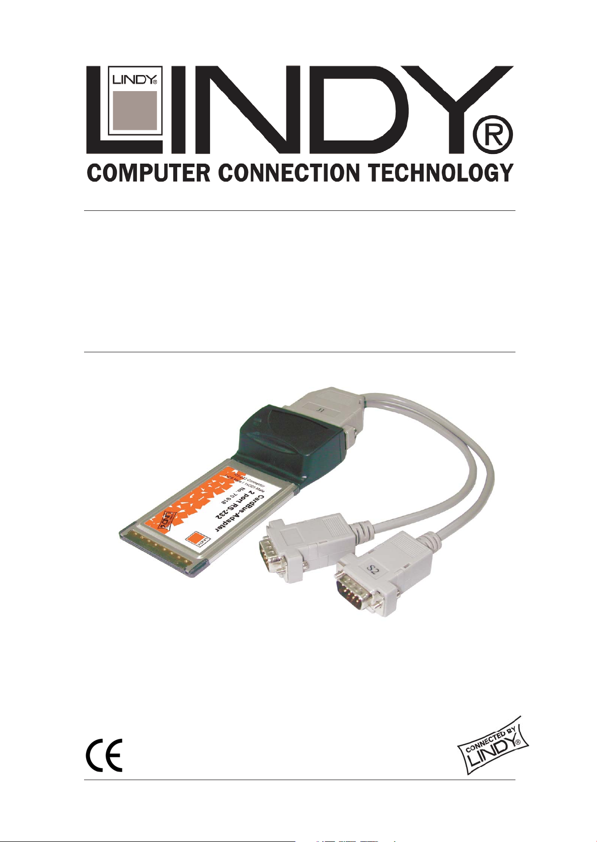
CardBus/PCMCIA
User Manual
English
2 Serial Ports
LINDY No. 70918
www.LINDY.com
© LINDY ELECTRONICS LIMITED & LINDY-ELEKTRONIK GMBH - FIRST EDITION (JUNE 2004)
Page 2

Introduction
Thank you for purchasing the RS-232 asynchronous serial PCMCIA card, an
ideal solution for adding additional ports to a wide variety of portable systems.
This Card Bus is your best solution to utilize the peripheral with serial port in an
easy-to-use environment such as plug-n-play and hot-swapping function.
For high performance is heavy multitasking environments, this Card Bus is
implemented with 16950 UART containing 128-byte FIFO. It provides ideal
connections to Modems, PDA, Digital Camera, Label printer, ISDN terminal
adapters, and barcode scanner via Notebook or any portable systems.
1.0 Features
Supports 32-bit Card Bus or PCMCIA Type II slot.
Plug-n-Play and Hot-swapping compatibility.
IRQ and I/O address assigned by BIOS.
Fast 16C950 Oxford CF950 high performance UART chipset.
128 byte receiver and transmitter FIFO.
High speed serial ports support baud rates up to 115Kbps.
Add two independent RS-232 serial ports on your laptop.
Provide maximum performance while taking up minimal system resources.
Automatic clock speed detection.
Memory-mapped operation for efficient throughput.
2.0 System Requirements
Pentium II or equivalent Notebook or PC computer.
One available PCMCIA Type II 32-bit Card Bus slot.
CD-ROM / DVD-ROM drive installed.
Driver support Microsoft Windows 95 / 98 / NT / 2000 / XP.
3.0 Packing List
Please check if the following items are present and in good condition upon
opening your package. Contract your vendor if any items are damaged or
missing.
Hardware:
Card: PCMCIA Type II 32-bit Serial Card Bus x 1
Cable: 44 Pin male connector to 2 Serial ports DB9 male x 1
CD Driver x 1
User Manual x 1
Page 3
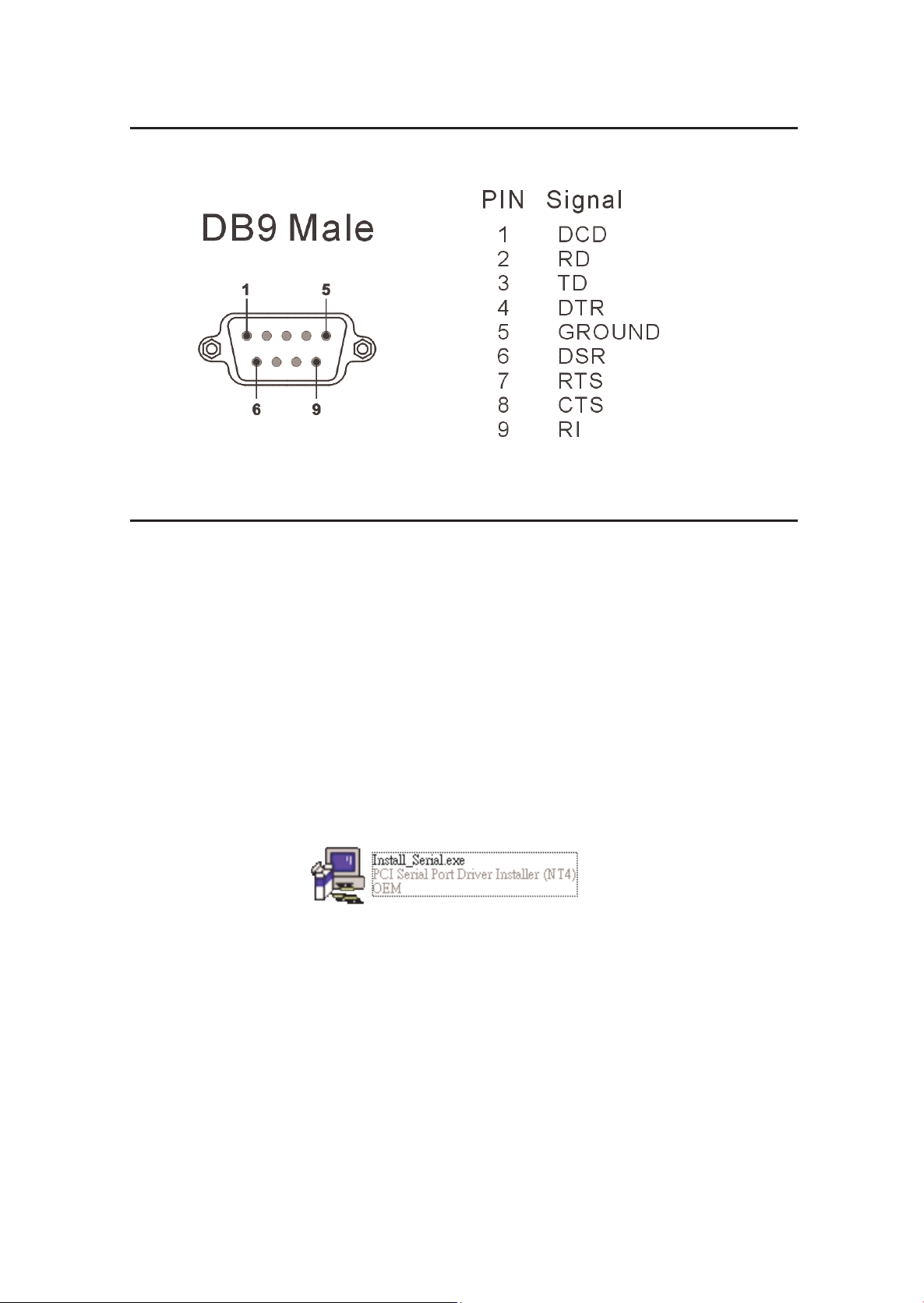
4.0 Pin Assignment
5.0 Driver Installation
Windows NT4.0
1. Power up the system.
2. After inserting the Serial Card Bus into PCMCIA Type II slot successfully,
please follow the instructions as below:
3. Please run the “Install_Serial.exe” program locate within folder of the
attached driver CD :
\PCMCIA\IO\CBS2000X\WinNT4\Install_Serial.exe
4. When the installation application starts, click “Next” to continue,
5. Ensure “Install” is selected, then click “Next”.
6. Click “OK” to accept the license agreement.
7. The system will install the driver and start it.
The ports are immediately ready for using.
3
Page 4

Windows 9x/2000/XP
1. Power up the system.
2. After inserting the Serial Card Bus into PCMCIA Type II slot successfully,
please follow the instructions as below:
3. System will show the “Found New Hardware Wizard” windows.
a. You can select “Install the software automatically”.
Let system searching and installing the appropriate driver automatically.
b. You can select “Install from a list or specific location”.
Please specify the driver locate within folder of the attached driver CD :
\PCMCIA\IO\CBS2000X\
4. System will search the “PCcard OX16CF950” driver and show the software
installation warning windows. Select “Continue Anyway” to install driver.
5. After installing driver successfully, please select “Finish” to complete the
driver installation steps.
4
Page 5

Note:
5.0 Verifying Installation
The “Add New Hardware Wizard” windows will show up and re-install driver
several times until you finish setting up each serial port.
Please right click “My Computer”, select “Properties”, and “Hardware”, then
“Device Manager” to verify the driver installation completed.
If there is any yellow exclamation mark on "PCcard OX16CF950", please
remove this item from the Device Manager by clicking the Uninstall button
and click Refresh to reinstall this driver again.
5
Page 6

6.0 Configure COM Port
1. Select the COM Port which you want to configure, for example COM4.
Right check the mouse, and select the “Properties”.
2. You can configure different operating settings through selecting the “High
Speed Communications Port” properties pages.
3. Please select “Settings” to configure standard Baud rate, Data bits, Parity,
Stop bits and Flow control options, then select “Advanced Setting” to
choose COM port number as picture shown.
NOTE:
RS-422/485 option is useless in this mode.
6
Page 7

3. You can select “FIFOs” change the length of receiver and transmitter FIFO.
This page is used to configure the FIFO trigger levels, i.e. at what fill levels the device will generate an
interrupt, or apply automati c f l ow cont rol. I n addi t i on, t he FI FO can be com pl et el y disabl ed; al t hough t hi s i s
not recommended for normal operation. The f our sli ders all ow adj ust m ent of t he various t rigger level s in
550 and 950 modes. These are described below:
Transmitter FIFO interrupt t rigger level - When the l evel of data in the transmit FI FO f al ls bel ow t his
value, a transmitter interrupt is triggered. Setting this value to zero will not trigger an interrupt until the
transmitter is completely idle.
Receiver FIFO interrupt trigger level - When the level of dat a i n t he receiver FIFO reaches t his
value, a receiver data interrupt is triggered.
Flow On flow-control li m i t - When the level of dat a i n t he receiver FIFO reaches thi s value as dat a
is read from the FIFO, a handshake i s triggered t o instruct the remote transmit t er that i t i s f ree to
transmit data (E.g. Transmi t an XO N character to t he remot e m achi ne).
Flow Off flow-control limit - When the level of data in the receiver FIFO reaches this value as it fills
up, a handshake is triggered to instruct t he remot e transmitter to stop sendi ng dat a as t he FI FO is
becoming full. (E. g. Transmi t an XOFF charact er to t he remot e m achine).
The FIFO trigger levels can be fine t uned t o gai n opt i m um performance, dependi ng on syst em
performance, baud rate used, levels of serial t raff i c et c.
7
Page 8

4. You can select “Data Rate” change the crystal Frequency of input clock.
This page provides a list of comm on cryst al val ues used wi t h C O M ports. Sel ect “Detect crystal
frequency” to det ect t he i nput cl ock f requency to t he U AR T. (This requires t hat t he port i s not currently i n
use by another application).
The baud rate can optionally be adjusted according t o the data rate required. To enable the advanced
baud rate configuration options, desel ect t he “Use default baud rat e” box. In normal operati on, t he driver
will generate the desired baud rate from the crystal frequency. The quad speed option will multiply all
application selected baud rates by 4 by utilising the OX16C95x Times clock register (TCR). The driver can
multiply thi s baud rate, or divi de i t usi ng t he Cl ock Prescaler register (CPR).
The clock pre-divisor is used to divide the input clock prior to baud rate generation. This m eans a hi gh
speed crystal (e.g. 50MHz) can be pre-divided to generate standard baud rates (In t hi s case 50 / 27. 125 =
1.8433 MHz, which will emulate a 1.8432 MHz crystal with less than 0. 01% bit rate error). Alternatively, the
pre-divisor could be switched off t o al low dat a rates up t o 12.5Mbps to be generated.
8
Page 9

g
g
This device complies with Part 15 of the FCC Rules.
Operation is subject to the followin
(1) this device may not cause harmful interference,
and (2) this device must accept any interference
received, includin
undesired operations.
9
interference that may cause
two conditions:
 Loading...