

Page 1
© LINDY ELECTRONICS LIMITED & LINDY-ELEKTRONIK GMBH - FIRST EDITION (Feb 2005)
USB 2.0
Card Reader Panels
User Manual English
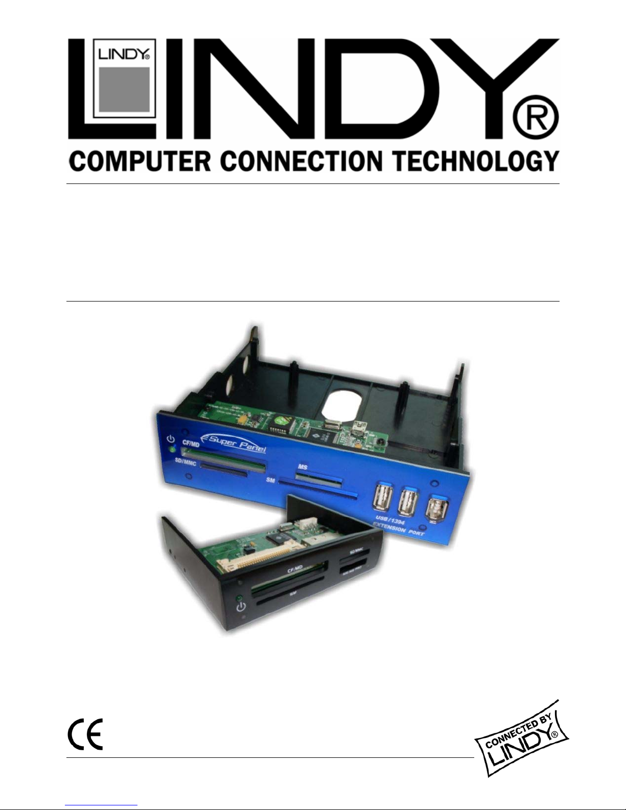
LINDY No. 42896 5.25” Card Reader Panel
LINDY No. 42897 3.5” Card Reader Panel
www.lindy.com
Page 2
Installation Instructions 5.25” Card Reader Panel (No. 42896)
Software Installation
Users of Windows XP/ME/2000(SP3) DO NOT need to install drivers. Windows will automatically provide a USB
2.0 device driver for the card reader.
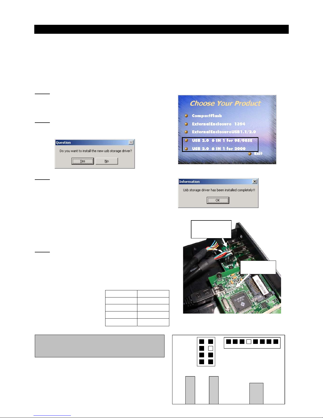
Win 98SE/2000 users need to install the software using the supplied CD. Please install the software before fitting
the card reader into your computer. Insert the CD and follow the on screen instructions as below:
Step 1
Select the correct driver for your operating system – Windows
98 or Windows 2000.
Step 2
When prompted click Yes to install the driver:
Step 3
Once the driver has installed, the following box will appear:
Click OK to complete the installation
Hardware Installation
FireWire Connection Pins
USB Connection Pins
GND (Black)
VCC (Red)
DATA + (Green)
DATA - (White)
VCC
GND
Note: We recommend you use anti-static precautions when
installing the card reader
Step 1
Connect the supplied cables to the connectors in the card reader
assembly. The mini-USB connector plugs into the connector on
the card reader circuit board and the FireWire and Type A USB
extension cables install onto the connector pins on the
USB/FireWire Extension circuit board.
Colour Signal
Red VCC
White DATA Green DATA +
Black GND (VCC-)
Card Reader
Circuit Board
USB / FireWire
Extension Ports
Circuit Board
The USB cables attach to the
motherboard and the card
reader using the coloured
wires identified in this table:
CAUTION: To avoid damaging the card reader you
must ensure the VCC, DATA+, DATA- and GND
wires connect to the correct pins.
The diagram to the right, illustrates the pin layout of the
USB and FireWire connectors on the USB/FireWire
Extension Ports circuit board
Page 3
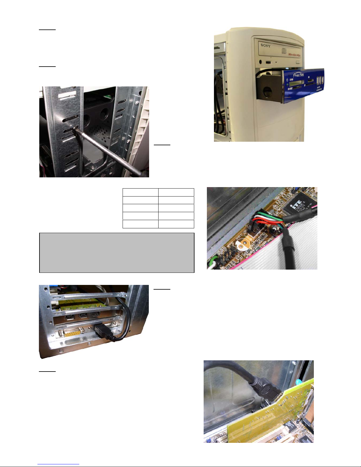
Step 2
Switch off your computer, and unplug from the mains. Remove the
case cover and install the card reader assembly into a spare 5.25“
bay in your computer
Step 3
Secure the card reader using the supplied screws
Step 4
Next, connect the USB cables from the card reader circuit board and
USB extension port circuit board to a USB pin header on your
motherboard or USB add-on card. (Check the manual that came
with your motherboard / USB card to locate the USB pin header)
Colour Signal
Red VCC
White DATA Green DATA +
Black GND (VCC-)
The four pin connectors from
the card reader install onto the
pin header using the wires
identified in this table:
CAUTION: To avoid possible damage to your hardware
you must ensure that the VCC, DATA+, DATA- and
GND wires connect to the correct pins on the pin
header. Consult your motherboard / USB add-on card
manual to identify the correct pin assignment.
Step 5
Connect the Type A USB Male connector from the USB Extension
port to a spare internal USB Female socket on your motherboard or
add-on card.
If no internal connection is available you can route the USB cable
through the back of the computer to an external port (see picture)
Step 6
Connect the FireWire connector from the FireWire extension port
circuit board to an internal FireWire socket on your motherboard
or add-on card (see picture).
If no internal connection is available you can route the FireWire
cable through the back of the computer to an external port.
Replace the case cover and power up your computer. Windows
will detect the Card Reader panel and automatically install the
drivers.
Page 4
Installation Instructions 3.5” Card Reader Panel (No. 42987)
Software Installation
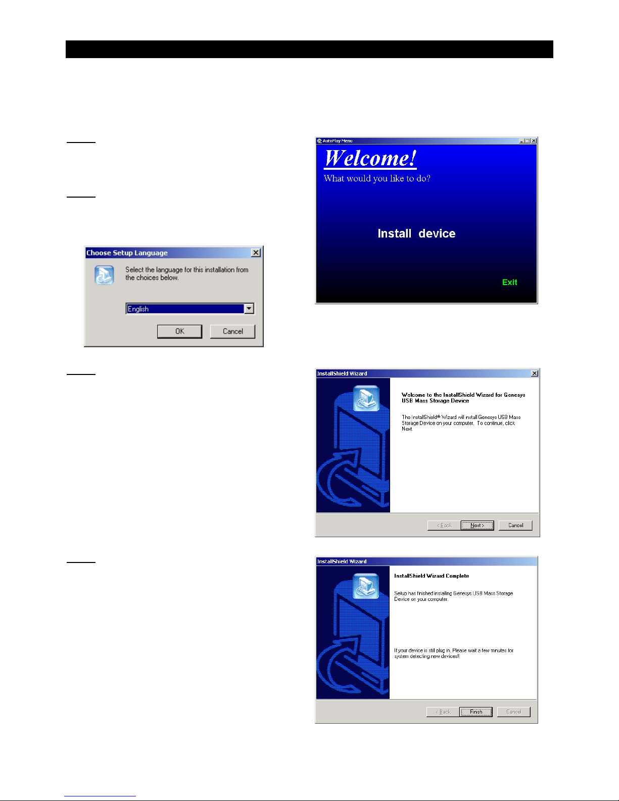
Win 98SE/ME/2000/XP users need to install the software using the supplied CD. Please install the software before
fitting the card reader in your computer. Insert the CD and follow the on screen instructions as below:
Step 1
After the Welcome menu appears click Install device to
begin.
Step 2
Choose your preferred language from the drop-down list
and then click OK.
Step 3
Click NEXT to install the USB Mass Storage Device
Step 4
Click Finish to complete the software installation
Page 5
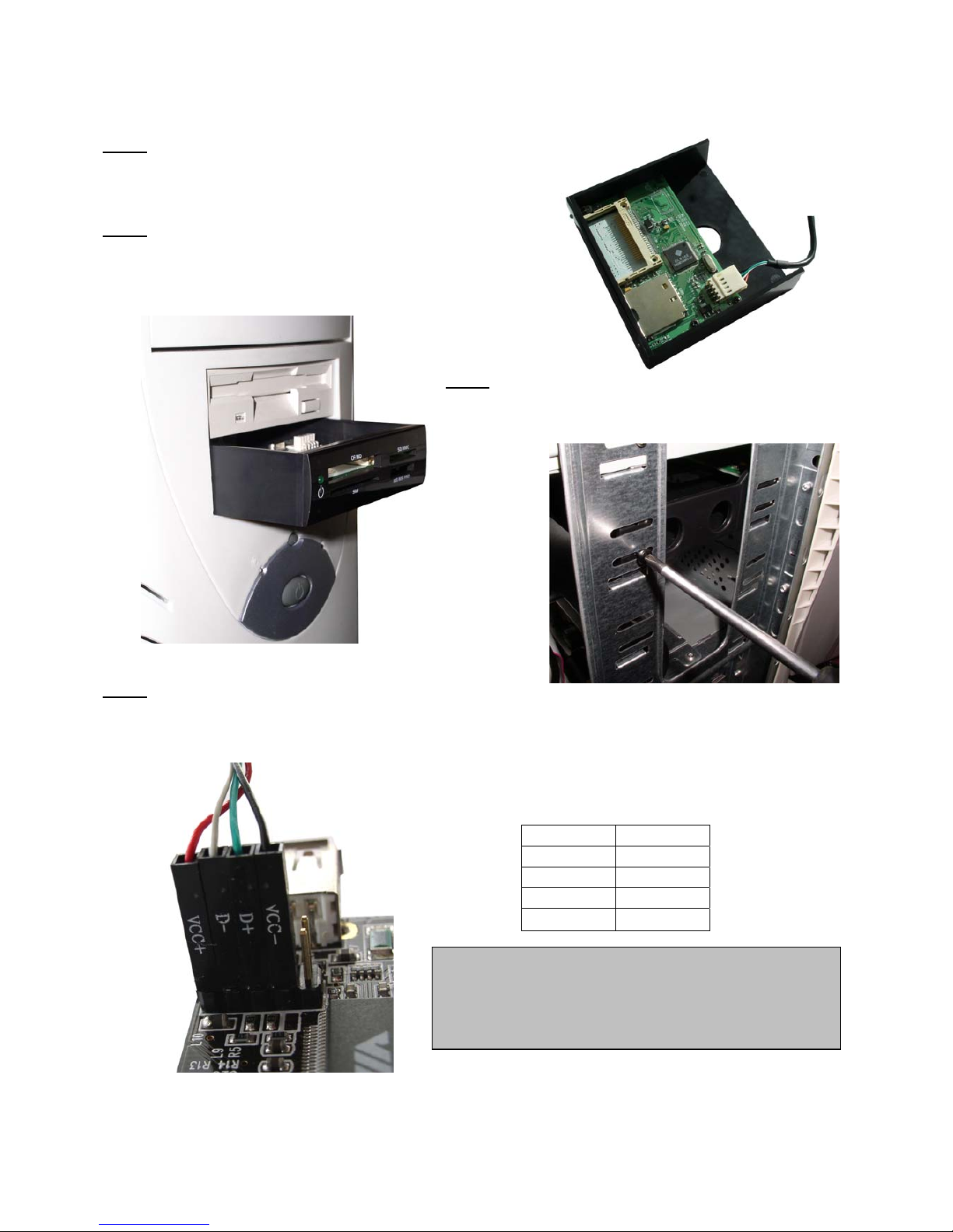
Hardware Installation
Note: We recommend you use anti-static precautions when installing the card reader
Step 1
Connect the supplied USB internal cable to the connector on the
Card Reader
Step 2
Switch off your computer, and unplug from the mains. Remove
the case cover and install the card reader assembly into a spare
3.5" bay in your computer
Step 3
Secure the card reader using the supplied screws
Step 4
Next, connect the USB cable from the card reader circuit board to a USB pin header on your motherboard or USB
add-on card. (Check the manual that came with your motherboard / USB card to locate the USB pin header)
The four pin connectors from the card reader install onto the pin
header using the wires identified in this table:
Colour Signal
Red VCC +
White DATA Green DATA +
Black VCC- (GND)
CAUTION: To avoid possible damage to your hardware
you must ensure that the VCC+, DATA+, DATA- and
VCC- (GND) wires connect to the correct pins on the
pin header. Consult your motherboard / USB add-on
card manual to identify the correct pin assignment.
Replace the case cover and power up your computer. Windows will detect the Card Reader panel and
automatically install the drivers.
Page 6
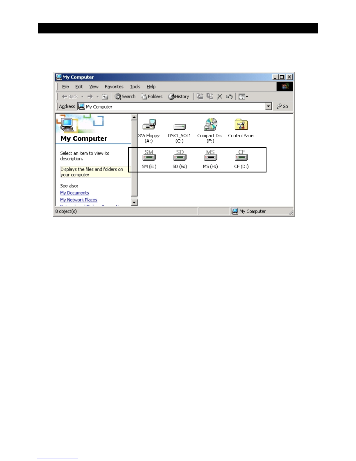
Using the Card Reader
The first time you power up your computer after you have installed the Card Reader, Windows will automatically
detect and install the relevant drivers.
Once this process is complete you can begin using your Card Reader!
Windows identifies each different memory card slot in the Card Reader as a removable drive. Simply insert your
memory card into the slot and access the data in the same way you would a regular hard drive!
Page 7

Shielded cables must be used with this equipment to maintain compliance with radio frequency
energy emission regulations and ensure a suitably high level of immunity to electromagnetic
disturbances.
FCC Warning
This equipment has been tested and found to comply with the limits for a Class B Digital device, pursuant
to part 15 of the FCC Rules. These limits are designed to provide reasonable protection against harmful
interference in a residential installation. This equipment generates, uses, and can radiate radio frequency
energy and, if not installed and used in accordance with the instructions, may cause harmful interference
to radio communications. However, there is no guarantee that interference will not occur in a particular
installation. If this equipment does cause harmful interference to radio or television reception, which can
be determined by turning the equipment off and on, the user is encouraged to try to correct the
interference by one or more of the following measures:
y Reorient or relocate the receiving antenna
y Increase the separation between the equipment and receiver
y Connect the equipment into an outlet on a circuit different from that to which the receiver is connected
y Consult the dealer or an experienced radio/TV technician for help
You are cautioned that changes or modifications not expressly approved by the party responsible for
compliance could void your authority to operate the equipment.
Th
is device complies with part 15 of the FCC Rules.
Operation is subject to the following two conditions:
1. This device may not cause harmful interference, and
2. This device must accept any interference received, including interference that may cause undesired operation
For Home and Office Use
Tested to comply
with FCC Standards
LINDY No. 42896; 42897
 Loading...