

Page 1

USB 2.0 IP Device Server
User Manual English
____________________________________________________
LINDY No. 42829
© LINDY ELECTRONICS LIMITED & LINDY-ELEKTRONIK GMBH - FIRST EDITION (Oct.2008)
For Home and Office Use
Tested to Comply with
FCC Standards
www.LINDY.com
Page 2

English Manual
Table Of Contents
1. Introduction ......................................................................................................................................... 3
EN 2
2. Windows utility ................................................................................................................................... 3
2.1. TheVirtual USB-IP Driver Software .......................................................................................... 4
2.2. Device Mapping ............................................................................................................................ 5
2.3. Server Manager ........................................................................................................................... 7
2.3.1. Server Configuration ............................................................................................................ 9
2.3.2. Firmware Upgrade .............................................................................................................. 12
2.3.3. Restore factory defaults. ..................................................................................................... 13
2.4. Printer Auto-Connect ................................................................................................................ 13
3. Web Server ........................................................................................................................................ 14
3.1. Network Settings ....................................................................................................................... 15
3.2. Secure NAS Settings .................................................................................................................. 16
3.2.1. Shares setting ....................................................................................................................... 17
3.2.2. User Settings ........................................................................................................................ 18
3.2.3. IPSec Security Settings ...................................................................................................... 19
3.2.4. The Status page ................................................................................................................... 20
3.3. Virtual USB-IP Settings............................................................................................................. 21
3.3.1. The Status Page ................................................................................................................... 21
3.3.2. The Upgrade Page ............................................................................................................... 22
4. Accessing the Network drive ............................................................................................................ 24
Page 3

EN 3
1. Introduction
The USB 2.0 DEVICE SERVER Combo solution not only allows you to add storage space onto your
home or office network but also allows you to work with the remote USB devices over a local network as
if they were connected directly to your local PC.
Key Features of the application are
• Integrated USB-IP and NAS solution
• USB Port 0 and Port 1 are USB NAS ports. Any Mass storage devices connected to these
ports will be detected as NAS drives
• The USB Port 2 and Port 3 are USB-IP ports, any device connected to these ports can be
virtualized on to the client PC
• Allows USB Devices to be used and shared by client PC's on LAN
• Supports wide variety of USB devices
• Supports Ethernet networks 10/100Base-T via RJ-45
• Supports printer auto-reconnect while sharing the printer from Client PC's
• Supports auto sharing of USB devices
• Supports USB device safe removal
• User-Friendly application interface
The USB 2.0 Device Server solution enables on-the-go connection of USB Storage drives onto the 2 USB
ports.
The USB Port 0 and Port 1 are USB NAS ports. Any Mass storage devices connected to these ports will
be detected as NAS drives and needs to be manually shared onto the network. Any other device
connected to these ports will not be detected or available.
The USB Port 2 and Port 3 are USB-IP ports, any device connected to these ports can be virtualized on to
the client PC using the USBIP ADMIN Utility.
Access to the Network disks USB can be password protected and can be securely accessed over the
network. The USB 2.0 Device Server Application has IPSec feature which utilizes the built-in Hardware
Encryption Block to establish a Virtual Private Network (VPN) on-the-wire security.
2. Windows utility
The USBIP Admin utility Setup is an Install Shield based application, which can be used for installing,
uninstalling and upgrading the Client Software for the USB 2.0 Device Server. Please run the selfexplanatory Install shield application to install the Admin Utility.
The Admin utility is an application, which virtualizes the devices that are connected on the remote USBServer. The USBIP Admin utility can also be used for configuring the USB server device (on the board).
Page 4

EN 4
2.1. TheVirtual USB-IP Driver Software
This contains a Virtual Bus Enumerator driver & Virtual Bus driver. These drivers will help in vitalizing
the USB devices, for each attached device on the USB-Server.
Virtual Bus driver takes the USB traffic from the USB Client drivers and passes it to the USB-Server,
which is sitting remotely on the network.
As soon as the utility is installed this application icon will be placed in the system tray as shown in the
figure below.
Double click the icon on the system tray to view the Full screen mode of the PC client application as
shown below.
The application has four panels, which are docked in the application.
1) Main window: This displays all the Device server and the USB Devices connected on them
2) Function Panel: This panel enables to switch between the Device Mapping and Server
Manager Application.
3) Device Details Panel: This displays the more verbose information of the server and the device
selected on the main window.
4) Log panel: Any event on the USB server creates a log in the Log panel. This helps in
continuous monitoring of USB device servers on the network.
The Admin Utility has two main functionalities built in
a) Device Mapping
b) Server Manager
Page 5
EN 5
2.2. Device Mapping
Device Mapping enables virtualization of all USB Devices connected to the USB 2.0 DEVICE SERVER
unit in your LAN on your local PC.
Click on the Green Arrow Button in the Admin utility to start the device mapping, which will
automatically start the ‘Found New Hardware’ wizard to install the Virtual USB driver.
Continue the Add New Hardware wizard to install the Virtual USB driver for the USB 2.0 DEVICE
SERVER Admin utility.
Select “Search for a suitable driver for my device (recommended)” and click on ‘Next’, the Operating
System automatically will search for the driver until the Virtual USB over IP driver is installed.
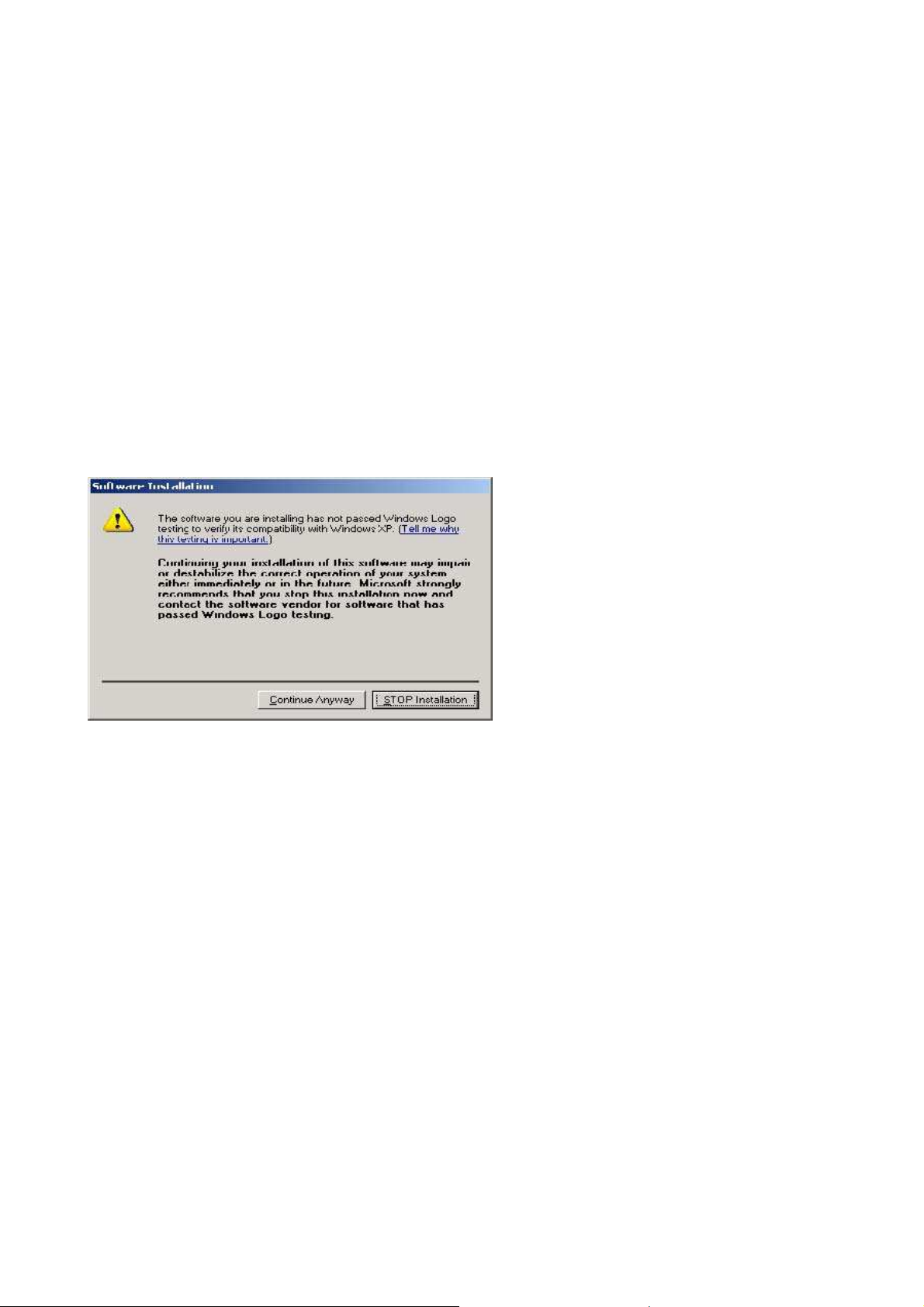
Please Click on “Continue anyway” if a Windows dialog pops up about the Digital Signature as shown
below.
Power on the USB 2.0 DEVICE SERVER board and connect an Ethernet cable from the USB 2.0 Device
Server Ethernet port to your Local Area Network.
The USBIP Admin utility is capable enough to identify the USB 2.0 DEVICE SERVER USB servers by
it’s IP address on the network. As soon as the USB 2.0 DEVICE SERVER box is detected with a specific
IP address the Windows automatically invokes a Found New Hardware Wizard to install the drivers for
the USB server box.
NOTE: For proper enumeration of device remove the Firewall from the Windows Machine.
Page 6

EN 6
Continue the Installation to see the USB 2.0 DEVICE SERVER board and the USB devices connected in
the Admin utility as shown below.
In the Device mapping window, all the USB devices are shown as a tree under the USB Server.
Right click on any device and click on “Connect” to virtualize that USB device onto your PC as shown
below .
Page 7
EN 7
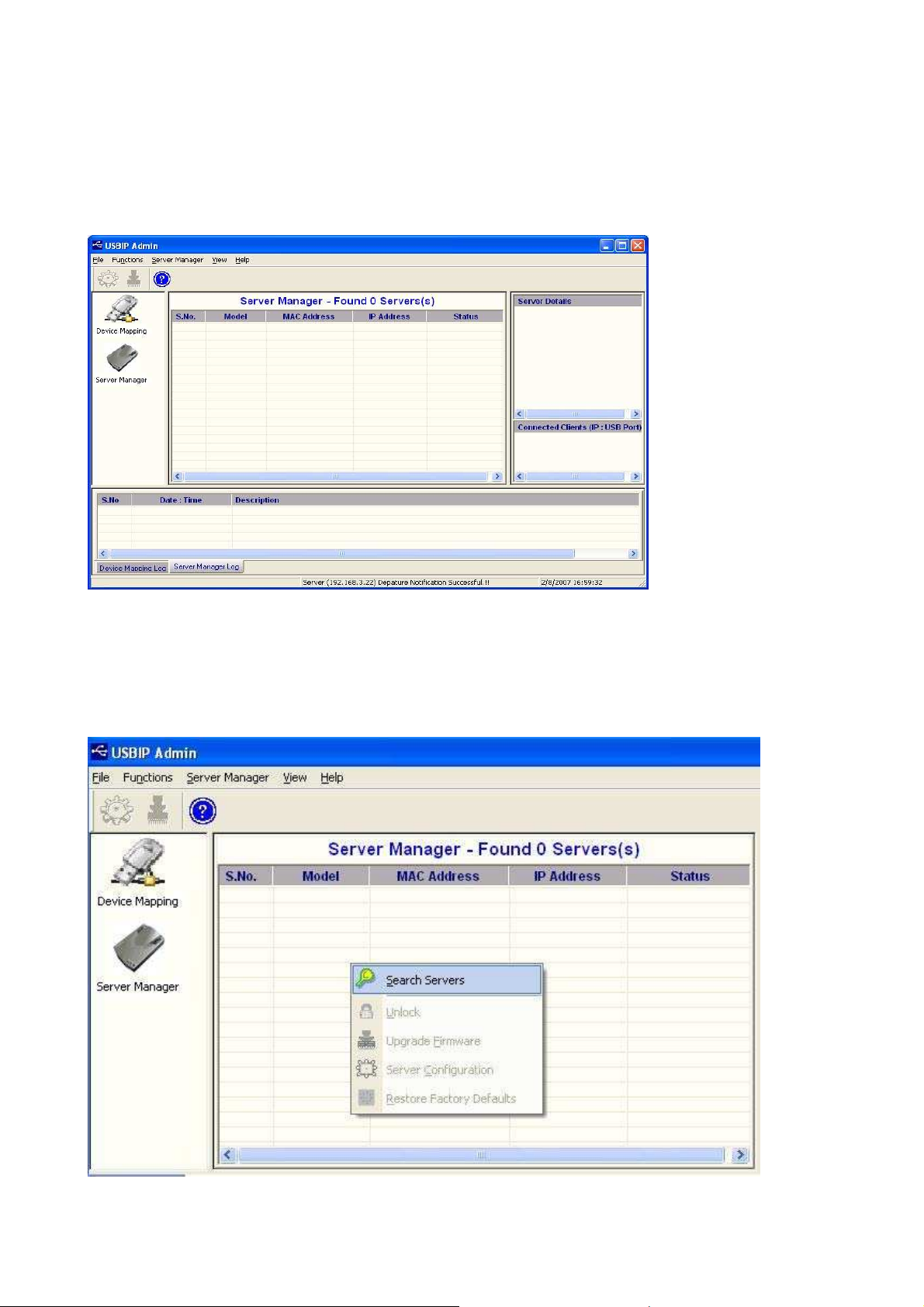
2.3. Server Manager
The Server manager enables the Administrator to configure the USB 2.0 Device Server via the network.
The Server Manger also has an option to search for the device on the Network:
Right Click on the Server Manager Main window and Click on Search server as shown below .
Page 8
EN 8
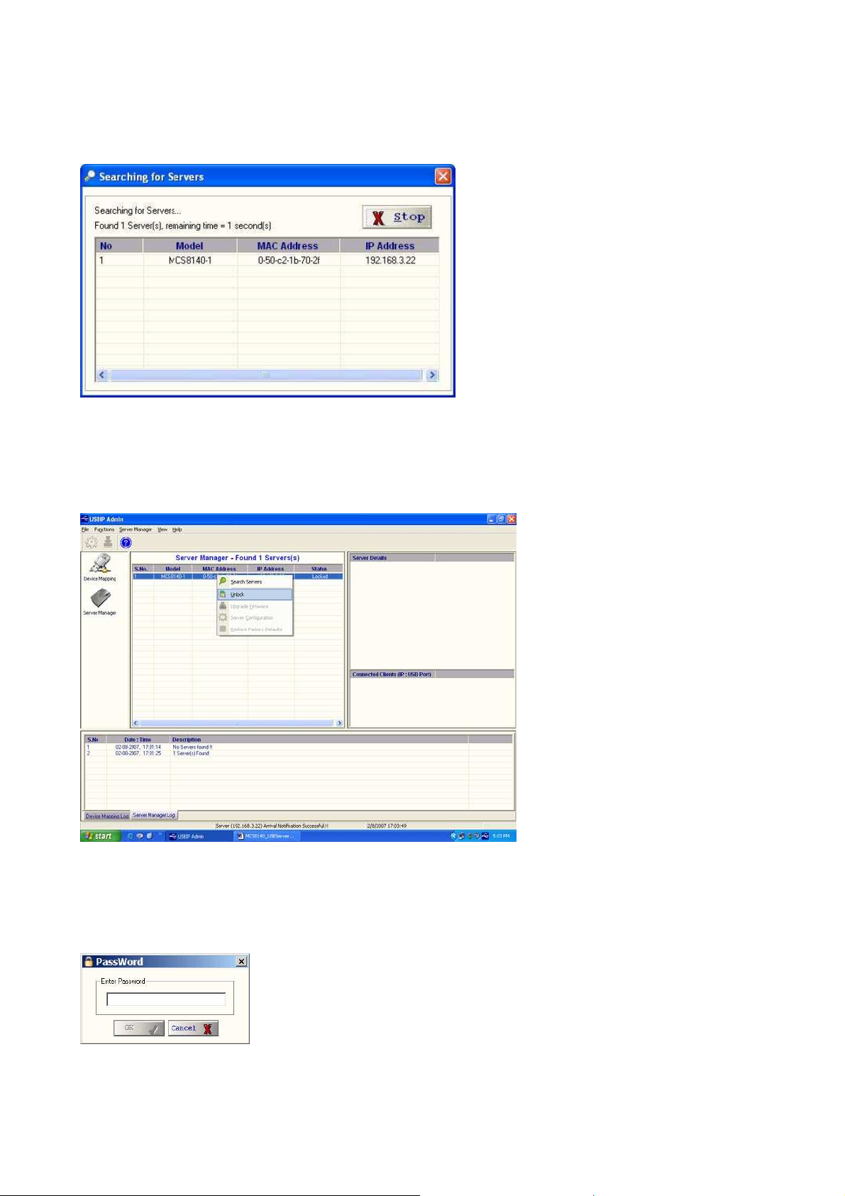
The dialog ‘Searching for Servers’ dialog will appear and list all the USB 2.0 Device Server devices on
the Network as shown below
.
The USB Device Server search is password protected and should be unlocked in order to configure the
selected device.
On selecting ‘Unlock’ the password dialog pops up as shown below. Key in the password in the
‘Password’ dialog. The default password for the USB IP Server is “combo”
If the Authentication has been successful an ‘Unlock OK’ dialog appears. The Device server can now be
configured for various settings as given below.
Page 9

EN 9
2.3.1. Server Configuration
The Server Manager has an option to change Server Configuration settings through USBIP Admin Utility.
To open server configuration window right click on the USB 2.0 DEVICE SERVER server displayed on
the Server Manager Main window and select “Server Configuration” option as shown below.
The Server Configuration window will appear as shown below.
Page 10

Basic Settings:
The Basic Settings page allows you to specify a server name. Check the modify box and enter server
name as shown below.
IP Settings:
EN 10
The IP Settings page allows you to modify MCS 8140-D box IP Address as shown below.
The Default IP Address is 192.168.3.22
To modify the IP Address of the USB 2.0 DEVICE SERVER box, check the ‘Modify’ box and Select IP
Configuration (Select IP configuration Static/DHCP from IP Configuration drop-down box) as shown
below.
Page 11

EN 11
After selecting IP Configuration key in the IP Address of the USB 2.0 DEVICE SERVER box in the IP
Address field followed by proper Subnet Mask & Gate Way as shown below.
After entering IP address, Subnet Mask & Gate Way then click on “save” button. Then USBIP Admin
shows a progress bar, after the process is finished, the following message box will be displayed.
Note: Every unit in the network is identified by its IP address. The utility treats each IP address as unique
device. If the IP address of the box is modified, the software treats the same box as a different device and
will open a Found New Hardware Wizard.
Continue the Found New Hardware Wizard to install the Virtual USB-over-IP bus driver.
Now USB 2.0 DEVICE SERVER box appears with changed IP Address under USBIP Admin utility.
Password:
The Password Settings page allows you to change or Enable/Disable password of the USB 2.0 DEVICE
SERVER box. The Password settings page will be as shown below.
Check the Modify box to Enable or Disable password option to USB 2.0 DEVICE SERVER box.
Page 12

EN 12
2.3.2. Firmware Upgrade
The USB 2.0 Device Server Firmware can be upgraded remotely using the Firmware upgrade option.
Select the server on the Server manager. Right Click on the server and Select Upgrade Firmware option to
upgrade the firmware.
Select the file to be upgraded by click on the Browse option in the “Select File” dialog as shown below.
An upgrade.tar.bz2 file is required to upgrade the firmware. The upgrade .tar file can be downloaded from
our website www.lindy.com.
Click on “Transfer” to upgrade the firmware. A firmware upgrade status is displayed which automatically
relinquishes once the transfer is completed.
As soon as the transfer is completed, the USB 2.0 DEVICE SERVER USB server box automatically
restarts to apply the upgraded firmware settings.
Page 13

EN 13
2.3.3. Restore factory defaults
Right click on the USB 2.0 DEVICE SERVER in the Server Manager Window and select the Restore
Factory Defaults function to obtain Default settings as shown below.
Then USBIP Admin Utility pops up a window asking for to continue or not. If we select Ok button it will
get default settings.
2.4. Printer Auto-Connect:
USB Admin Utility enables Printers be shared between multiple clients making it a bidirectional Print
Server. In order to share the printer between multiple clients the user may need to connect the printer at
least once to install the driver for the Printer.
Once the printer is enumerated disconnect the Printer form the Device Mapping Window, Select the
Printer Auto Reconnect button
on the Menu bar to open the Printer Auto-Connect Window.
Page 14

EN 14
Select the Printer which was connected and Click on “Save” and close the Window.
Once the Printer is configured for Auto-Connect mode, It remains free as long as the Printer is connected
and becomes “Busy” only when a user prints to the printer connected.
Multiple User print jobs will be executed on a time sharing basis.
3. Web Server
The USB 2.0 DEVICE SERVER Combo has a user-friendly web browser interface to configure the box.
To open the web interface just type the IP address of the box, i.e: http://192.168.3.22:901 in the browser.
(Make sure that the proxy server is disabled on your PC's Internet explorer).
A dialog prompts for the username and password. The username is “root” and the default password is
“combo".
Page 15

If the authorization has been successful, the home page of the USB 2.0 DEVICE SERVER NAS
application will be visible as shown below.
EN 15
3.1. Network Settings
The “Network” tab allows you to configure both wired as well as wireless interfaces. For the wired side
we can configure the Static IP manually or set the box to automatically obtain an IP address by setting to
the Dynamic (DHCP) mode. (Make sure that the DHCP server should be in ON).
If the user selects the Network Interface type as “Wireless LAN” the browser shows the Wireless
configuration web page as shown below.
Page 16

EN 16
Select the Server IP Type, and select Static in order to change the IP address, Subnet mask and Default
Gateway of the Box. If the choice is made as “Dynamic (DHCP)”, the box will automatically try to get an
IP Address from the wireless router available.
In the Wireless configuration the application can also list the Wifi access points available in the network
in the Wi-Fi Router Name.
If the choice has to be made to connect to a specific Wireless Router or access point choose “Select” radio
button and select the Wireless router in the dropdown menu.
3.2. Secure NAS Settings
The web-server has separate webpage to configure Secure NAS. Click on the Secure-NAS tab to view the
secure NAS settings in the Combo NAS USB IP solution.
Page 17

EN 17
3.2.1. Shares setting
The “Shares” tab is for creating/editing/deleting a share. A share is the partition of the disk that you want
others in the network to access. When a disk is connected to the NAS box the partitions and their statistics
will be shown in this page.
Specify the name in the “Enter a New Share Name” field to create a new share. If you have already
created a share then they will be shown in the “Select to Edit Share” and “Select to Delete Share” lists
that will allow you to edit/delete the shares.
When you click “Create Share” the parameters required for creating a new share are displayed.
Once a share is created by some the name (Ex: “flash_drive”), then you will be prompted to enter the
parameters for the share.
Page 18

• Select Partition: Select the partition which you want to access with the given share
name.
• Comment: Comments that you want to give for a share (optional setting)
• Validusers: Give the users separated with commas who are authorized to access this
share. If no user is listed then all will have access to that share. (optional setting)
• Readonly: Set read/write permissions for the share. Default is “No” which is
read/write permission.
• Guestok: Access the share with no password with account specified under guest
account.
• Browseable: This controls whether this share is seen in the list of available shares in a
net view and in the browse list.
• Available: This parameter lets you "turn off" a service. If available = no, then ALL
attempts to connect to the service will fail
For normal use you need not edit any parameters except selecting the required partition. Click on
“Commit Parameters” button and your share will be ready.
EN 18
3.2.2. User Settings
In the “Users” tab you can add/delete/enable/disable a user. You can also change the password for a
specified user. The list of registered users will be displayed at the bottom. Enabling/Disabling a user
means if a user has been created and you want the user not to access any share then you can disable that
user. Means he will not be entirely deleted but only restricted to access any share.
A username “moschip" is by default present, which is shown in the Registered User(s) table.
Page 19

EN 19
3.2.3. IPSec Security Settings
In the “Security” tab you can configure a VPN with a client for secure access to the box. The box uses
IPSec for establishing a VPN.
By default the security will be disabled. Then we have the encryption and authentication settings. The
USB 2.0 DEVICE SERVER NAS will support 3DES, AES128, AES192 and AES256 encryption
techniques and MD5, SHA1 authentication techniques.
The “Key Management” allows setting the type of key management whether Auto IKE (Internet Key
Exchange) or “Manual”.
In the below figure the “Auto (IKE)” is selected. Under this you have an option for enable/disable PFS
(Perfect Forward Secrecy) which is useful for key exchange. The “Pre-shared Key” field is to specify
what key to use and the “Key Life Time” field is the amount to specify the key lifetime in seconds.
The below figure is the “Manual” configuration of Key Management. Here we have to specify the
“Encryption Key” as well as the “Authentication Key”. Apart from these we have a SPI (Security
Parameter Index) field with which the SA’s (Security Associations) will be identified.
Page 20

EN 20
The connection status (Disconnected/Connected) will be displayed at the bottom in red.
Please check the Appendix section to know on how to configure IPSec on a Windows XP machine.
3.2.4. The Status page
In the “Status” tab you can view the NAS server status, active connections, active shares and opened files
in a very informative way.
The “Auto Refresh” button when clicked will keep on refreshing the page based upon the given refresh
time interval.
The “Active Connections” will display the IP addresses and the PC names that have connected to the
NAS box. In the “Kill” column you can close a connection by clicking “X” mark. But the client can reestablish the connection.
The “Active Shares” page will display which share is accessed by which client. The “Open Files” will
display which files are currently opened by which client. The file permissions are also displayed here.
Page 21

EN 21
3.3. Virtual USB-IP Settings
The web-server has separate webpage to configure Virtual USB server settings. Click on the Virtual USB
tab to view the USB server settings in the Combo NAS USB IP solution.
3.3.1. The Status Page
Page 22

EN 22
The status page displays the current status of the USB devices attached.
• Device Status:
• Vendor Id
• Product Id
• Class Id
• Peer-ip address
• Status
This status page is updated automatically every 10 seconds and it shows the device connected to USB 2.0
DEVICE SERVER board.
The Device Status table shows the Vendor Id, Product Id, Class, Peer-IP and the Status of the Device
connected. The Peer-IP is the IP Address of the computer on which the device is currently accessed.
Whenever any Device is Busy the Status of that device changes to “BUSY” and whenever it is not being
used it changes to “FREE” as shown below.
3.3.2. The Upgrade Page
The Upgrade page allows you to upgrade the firmware.
Select the file to be upgraded by click on the Browse option on the Upgrade page as shown below.
Page 23

EN 23
A file named upgrade.tar.bz2 file is required to upgrade the firmware. If one is availableThe upgrade .tar
file can be downloaded from the LINDY website, www.lindy.com.
Click on “upgrade” to upgrade the firmware
Page 24

EN 24
A file successfully uploaded message is displayed and the webpage also indicates that the USB 2.0
DEVICE SERVER box is restarting to apply the upgraded firmware settings.
4. Accessing the Network drive
Ensure the PC IP Address and Box IP Address is in the same subnet.
The network drive will be available on “My Network places” of Windows operating system.
Goto My Network places> Entire Network>Workgroup>mcs8140 as shown below to access the network
drive on USB 2.0 DEVICE SERVER.
Shortcut: Goto Programs > Run. Type the IP address of the unit in the Run Dialog as show below.
Page 25

OR
Type the box name in the Run dialog as follows: \\mcs8140
EN 25
Page 26

Radio Frequency Energy, Certifications
FCC Warning
This device complies with part 15 of the FCC Rules.
Operation is subject to the following two conditions:
1. This device may not cause harmful interference, and
2. This device must accept any interference received, including interference that may cause
undesired operation.
CE Statement, EMC Compatibilty
This device complies with EN Standards EN55022 and EN55024 according to the relevant EC
EMC Directive. It must be used with shielded cables only to maintain EMC compatibility.
Dieses Produkt entspricht den einschlägigen EMV Richtlinien der EU und darf nur zusammen mit
abgeschirmten Kabeln verwendet werden.
LINDY Herstellergarantie
LINDY gewährt für dieses Produkt über die gesetzliche Regelung hinaus eine zweijährige
Herstellergarantie ab Kaufdatum. Die detaillierten Bedingungen dieser Garantie finden Sie auf der
LINDY Website aufgelistet bei den AGBs.
WEEE (Waste of Electrical and Electronic Equipment),
Recycling of Electronic Products
In 2006 the European Union introduced regulations (WEEE) for the collection and recycling of all
waste electrical and electronic equipment. The wheelie bin symbol shown indicates that this
product must not be disposed of with household waste. Instead the product must be recycled in a
manner that is environmentally friendly. For more information on how to dispose of this product,
please contact your local recycling centre or your household waste disposal service. Each
individual EU member state has implemented the WEEE regulations into national law in slightly
different ways. Please follow your national law when you want to dispose of any electrical or
electronic products.
More details can be obtained from your national WEEE recycling agency.
Germany / Deutschland
Die Europäische Union hat mit der WEEE Direktive umfassende Regelungen für die Verschrottung
und das Recycling von Elektro- und Elektronikprodukten geschaffen. Diese wurden von der
Bundesregierung im Elektro- und Elektronikgerätegesetz – ElektroG in deutsches Recht
umgesetzt. Dieses Gesetz verbietet vom 24.März 2006 an das Entsorgen von Elektro- und
Elektronikgeräten über die Hausmülltonne! Diese Geräte müssen den lokalen Sammelsystemen
bzw. örtlichen Sammelstellen zugeführt werden! Dort werden sie kostenlos entgegen genommen.
Die Kosten für den weiteren Recyclingprozess übernimmt die Gesamtheit der Gerätehersteller.
LINDY No 42829
1st Edition, Oct 2008
www.lindy.com
 Loading...