

Page 1
Mini USB 2.0 & FireWire Enclosure
SATA & IDE
User Manual English
LINDY No. 42807
www.lindy.com
© LINDY ELECTRONICS LIMITED & LINDY-ELEKTRONIK GMBH - FIRST EDITION (August 2008)
Page 2

Page 3

User Manual English
Introduction
Thank you for purchasing the LINDY Mini USB 2.0 and FireWire Enclosure. This enclosure has
been designed to complement and add extra storage capability to your Mac Mini. The small
footprint design allows it to be seated underneath a Mac Mini, but with its USB 2.0 and FireWire
400 combo interface, it can also be used with other suitably equipped Macs and PCs.
Features
For use with standard 3.5” SATA or IDE/ATA hard disks
USB 2.0 and FireWire 400 (IEEE1394a) combo interface
USB 2.0 interface is backwards compatible with USB 1.1 equipped computers
Connectors: 1 x USB 2.0 Type B Female; 2 x 6 Pin FireWire Female
Aluminium cover for heat dispersal
Low-noise fan-free design
Stylish blue power LED
System Requirements
Can be used with any of the following:
USB 2.0 equipped Mac with OS X
USB 1.1 equipped Mac with OS 9.2, OS X
FireWire 400 equipped Mac with OS 9.2, OS X
USB 1.1 or 2.0 equipped PC with Windows ME/2000/XP/Vista
FireWire 400 equipped PC with Windows ME/2000/XP/Vista
Package Contents
Mini USB 2.0 and FireWire Enclosure
Installation screws
2 foam feet
12V DC Power Adapter
1m, USB 2.0 cable
1m, FireWire cable
This manual
2
Page 4
User Manual English
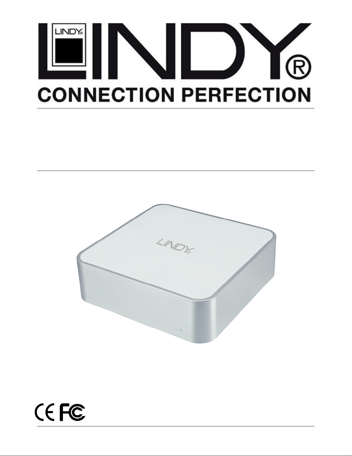
Hardware Assembly
Before starting the assembly make sure the jumper(s) on your hard drive are set to the Master
setting. Consult your hard disk manual or the manufacturer’s website for the correct jumper
setting.
1. Ensure that the Mini Enclosure is
disconnected from the mains, before
removing the 4 screws from the bottom of
the case
2. Remove the upper case
3. If you are using a SATA hard drive
continue to Step 4, if you are using an
IDE hard drive please skip to Step 5.
4. Connect the SATA Data and SATA
Power cables to the relevant connector
on your hard drive and continue to Step
12
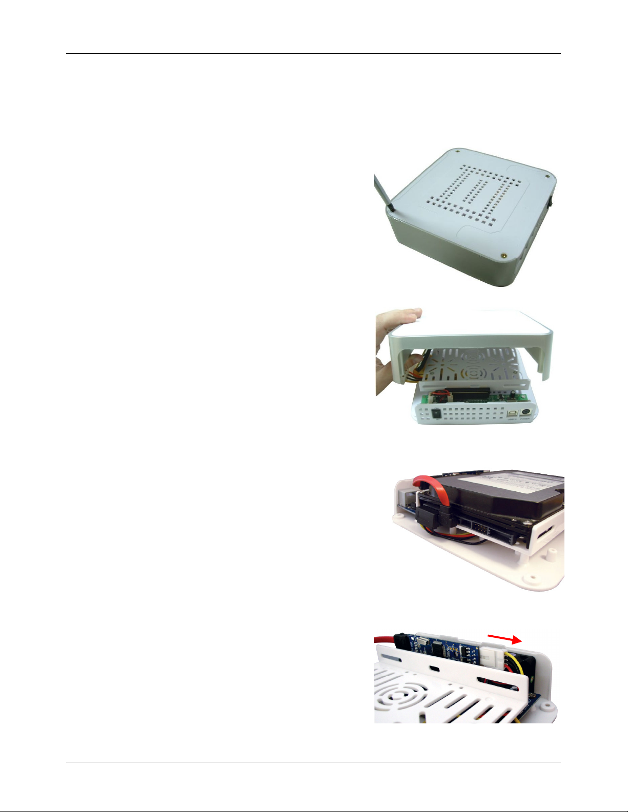
5. Before you can connect your IDE hard
drive you must first remove the SATA
Bridge Board and Molex to SATA power
cable.
6. Carefully disconnect the 4 pin power
connector, by holding the base of the
drive enclosure and pulling the connector
away from the bridgeboard.
3
Page 5

User Manual English
screws.
7. Disconnect the SATA Data cable from
the bridgeboard. Hold the base of the
drive enclosure and pull the bridgeboard
up to disconnect it.
8. Unscrew the four screws holding the
drive tray in place and remove the drive
tray.
9. Disconnect the Molex to SATA cable and
then replace the drive tray and insert the
10. Attach the provided IDE ribbon cable and
to the main board, in place of the bridge
board.
11. Place the hard drive into the drive tray and
connect the Molex power and IDE data
cables
4
Page 6

User Manual English
Note:
Boot up your computer first, and then switch on the drive enclosure to mount the drive.
12. Use the supplied screws to secure both
sides of the drive
13. Carefully assemble the top and bottom of
the case. If the upper case does not fit
properly, adjust the hard disk position
and try again
14. Replace the 4 case screws and affix the
two foam feet as illustrated
15. Connect the Power Cable to the Mini
Enclosure and the mains power supply.
Now connect the USB or FireWire cable
to the enclosure and to your computer.
Important: You can only make one
connection from your computer to the
housing via USB or FireWire. You cannot
connect to both the USB and FireWire
ports on the housing at the same time as
this will cause damage to the enclosure.
If you are using the FireWire interface, you can plug the cable into either of the
FireWire sockets. The second socket can be used for connecting another FireWire device in
series.
5
Page 7

User Manual English
Using the enclosure with your Mac
Mac Mini users: This enclosure is designed to sit underneath your Mac Mini.
If you want to use this enclosure with both PCs and Macs, then you should use a FAT32
formatted hard drive. If you are using a brand new drive, or want to erase an older drive you will
need to follow the instructions below:
CAUTION!
have made a backup of any files you do not want to erase, before proceeding!
After first booting up your computer and then connecting and powering up the enclosure, the
drive will mount and show up on your desktop, if it is a pre-formatted drive. No further action is
required.
However, if the drive is new and unformatted, you will see the following window appear:
1. Select Initialize to continue.
2. The Disk Utility application will launch:
Formatting the hard drive will destroy all the data on the drive. Make sure you
6
Page 8

User Manual English
3. Make sure the external drive is highlighted in the left hand pane and select the Erase tab.
4. Select your preferred Volume Format type from the drop-down menu. If you want to use the
drive with both Macs and PCs you should use MS-DOS File System. If you want to, you can
give the drive a name in the Name box.
5. Click the Erase button. A confirmation window will appear,
click Erase again.
When the erase process is complete,
the drive icon (as outlined) will appear on the desktop:
Dismounting the drive
NOTE!
external drive housing without dismounting the drive first!
To safely remove the drive with your Mac powered on, you should drag the drive icon to the
trash. You can then unplug the housing’s power and data cables if you want to disconnect the
drive.
To avoid losing data or damaging the drive, you should never turn off or unplug the
7
Page 9

User Manual English
Using the enclosure with your PC
If you want to use this enclosure with both PCs and Macs, then you should use a FAT32
formatted hard drive. If you are using a brand new drive, or want to erase an older drive you will
need to follow the instructions below:
CAUTION!
have made a backup of any files you do not want to erase before proceeding!
Windows 2000/XP/Vista users
After first booting up your computer and connecting and powering up the enclosure, Windows
will detect the drive and automatically install the relevant driver software.
If it is a pre-formatted drive, no further action is required; a new drive icon will show up in
Windows Explorer.
If you are using a brand new, unformatted drive, you will need to format the drive for use.
1. Right-click the My Computer icon on your desktop and from the drop-down menu, select
Manage.
2. The Computer Management window will appear. Select Disk Management from the left
hand pane.
3. In the right hand pane, the new drive will be identified as ‘Unallocated’. Right-click the drive
and, from the drop-down menu, select New Partition.
Formatting the hard drive will destroy all the data on the drive. Make sure you
4. The New Partition Wizard will appear. Follow the on-screen instructions to format and
partition the drive. Once complete, the new drive icon will show up in Windows Explorer and
the drive will be accessible.
8
Page 10

User Manual English
Safely Removing the Drive
To safely remove the drive from your system, click the Safe Removal icon on the Windows
taskbar. A dialogue box will appear:
Click on the box to safely remove the drive. Once the safe removal has been confirmed, you
can power down the enclosure and unplug it from your PC:
Windows Me users
After first booting up your computer and connecting and powering up the enclosure, Windows
will detect the drive and automatically install the relevant driver software.
If it is a pre-formatted drive, no further action is required; a new drive icon will show up in
Windows Explorer.
If you are using a brand new, unformatted drive, you will need to partition and format the drive
for use. To do this you need to run Fdisk.
For instructions about using Fdisk on a Windows Me PC, please visit the support section of the
Microsoft website.
9
Page 11

CE/FCC Information
CE Statement
This device complies with the European Regulations for Electromagnetic Compatibility (EMC) of
the European Union and it is equipped with the CE mark. This unit has to be used with high
quality shielded connection cables. Only if these high quality shielded cables are used it can be
sure that the EMC compatibility is not adversely influenced.
FCC Statement
Shielded cables must be used with this equipment to maintain compliance with radio frequency
energy emission regulations and ensure a suitably high level of immunity to electromagnetic
disturbances.
FCC Warning
This equipment has been tested and found to comply with the limits for a Class B Digital device,
pursuant to part 15 of the FCC Rules. These limits are designed to provide reasonable
protection against harmful interference in a residential installation. This equipment generates,
uses, and can radiate radio frequency energy and, if not installed and used in accordance with
the instructions, may cause harmful interference to radio communications. However, there is no
guarantee that interference will not occur in a particular installation. If this equipment does
cause harmful interference to radio or television reception, which can be determined by turning
the equipment off and on, the user is encouraged to try to correct the interference by one or
more of the following measures:
Reorient or relocate the receiving antenna
Increase the separation between the equipment and receiver
Connect the equipment into an outlet on a circuit different from that to which the receiver is
connected
Consult the dealer or an experienced technician for help
You are cautioned that changes or modifications not expressly approved by the party
responsible for compliance could void your authority to operate the equipment.
Page 12

Recycling Information
WEEE (Waste of Electrical and Electronic Equipment),
Recycling of Electronic Products
United Kingdom
In 2006 the European Union introduced regulations (WEEE) for the collection and recycling of all
waste electrical and electronic equipment. It is no longer allowable to simply throw away electrical
and electronic equipment. Instead, these products must enter the recycling process.
Each individual EU member state has implemented the WEEE regulations into national law in
slightly different ways. Please follow your national law when you want to dispose of any electrical or
electronic products.
More details can be obtained from your national WEEE recycling agency.
Germany / Deutschland
Die Europäische Union hat mit der WEEE Direktive umfassende Regelungen für die Verschrottung
und das Recycling von Elektro- und Elektronikprodukten geschaffen. Diese wurden von der
Bundesregierung im Elektro- und Elektronikgerätegesetz – ElektroG in deutsches Recht umgesetzt.
Dieses Gesetz verbietet vom 24.März 2006 an das Entsorgen von entsprechenden, auch alten,
Elektro- und Elektronikgeräten über die Hausmülltonne! Diese Geräte müssen den lokalen
Sammelsystemen bzw. örtlichen Sammelstellen zugeführt werden! Dort werden sie kostenlos
entgegen genommen. Die Kosten für den weiteren Recyclingprozess übernimmt die Gesamtheit der
Gerätehersteller.
France
En 2006, l'union Européenne a introduit la nouvelle réglementation (DEEE) pour le recyclage de
tout équipement électrique et électronique.
Chaque Etat membre de l’ Union Européenne a mis en application la nouvelle réglementation
DEEE de manières légèrement différentes. Veuillez suivre le décret d’application correspondant à
l’élimination des déchets électriques ou électroniques de votre pays.
Italy
Nel 2006 l’unione europea ha introdotto regolamentazioni (WEEE) per la raccolta e il riciclo di
apparecchi elettrici ed elettronici. Non è più consentito semplicemente gettare queste
apparecchiature, devono essere riciclate.
Ogni stato membro dell’ EU ha tramutato le direttive WEEE in leggi statali in varie misure. Fare
riferimento alle leggi del proprio Stato quando si dispone di un apparecchio elettrico o elettronico.
Per ulteriori dettagli fare riferimento alla direttiva WEEE sul riciclaggio del proprio Stato.
1st Edition August 2008
www.lindy.com
LINDY No. 42807
 Loading...