

Page 1
© LINDY Group - FIRST EDITION (May 2020)
Single Display Full Motion Wall Mount
User Manual English
Benutzerhandbuch Deutsch
Manuel Utilisateur Français
Manuale Italiano
No. 40973
lindy.com
Page 2

Page 3
User Manual English
Introduction
Thank you for purchasing the Single Display Full Motion Wall Mount. This product has been designed to
provide trouble free, reliable operation. It benefits from both a LINDY 2-year warranty and free lifetime
technical support. To ensure correct use, please read this manual carefully and retain it for future
reference.
The Lindy Single Display Full Motion Wall Mount is a high quality, secure solution for mounting a single
display to a brick or stud wall, with ability to freely tilt or horizontally move the display. The mounts lowprofile, slim design provides a flush fit of the display to the surface, ensuring an aesthetically pleasing
setup in residential or professional AV installations, while the cantilever arm allows for simple access to
the rear panel connections. The display is easily adjusted horizontally, or with a 15° tilt , to provide the
most comfortable viewing experience.
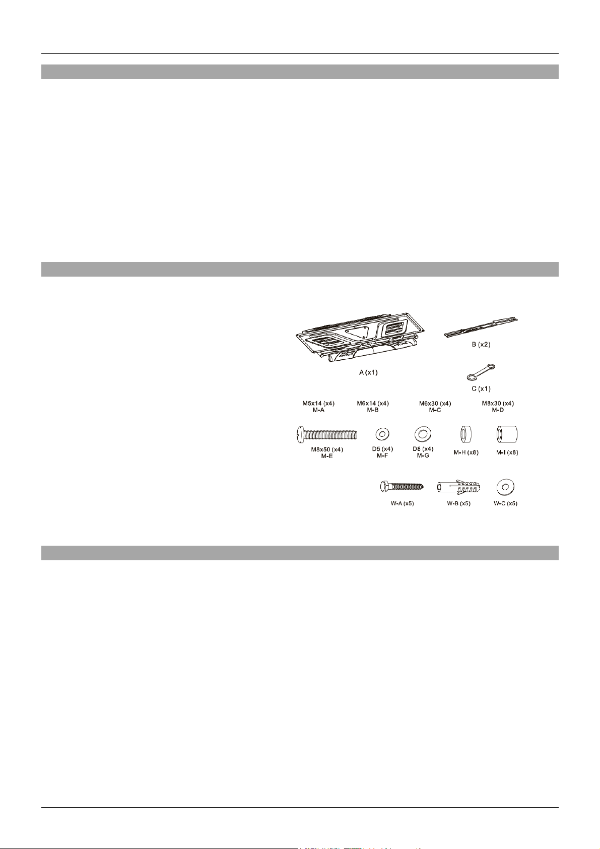
Package Contents
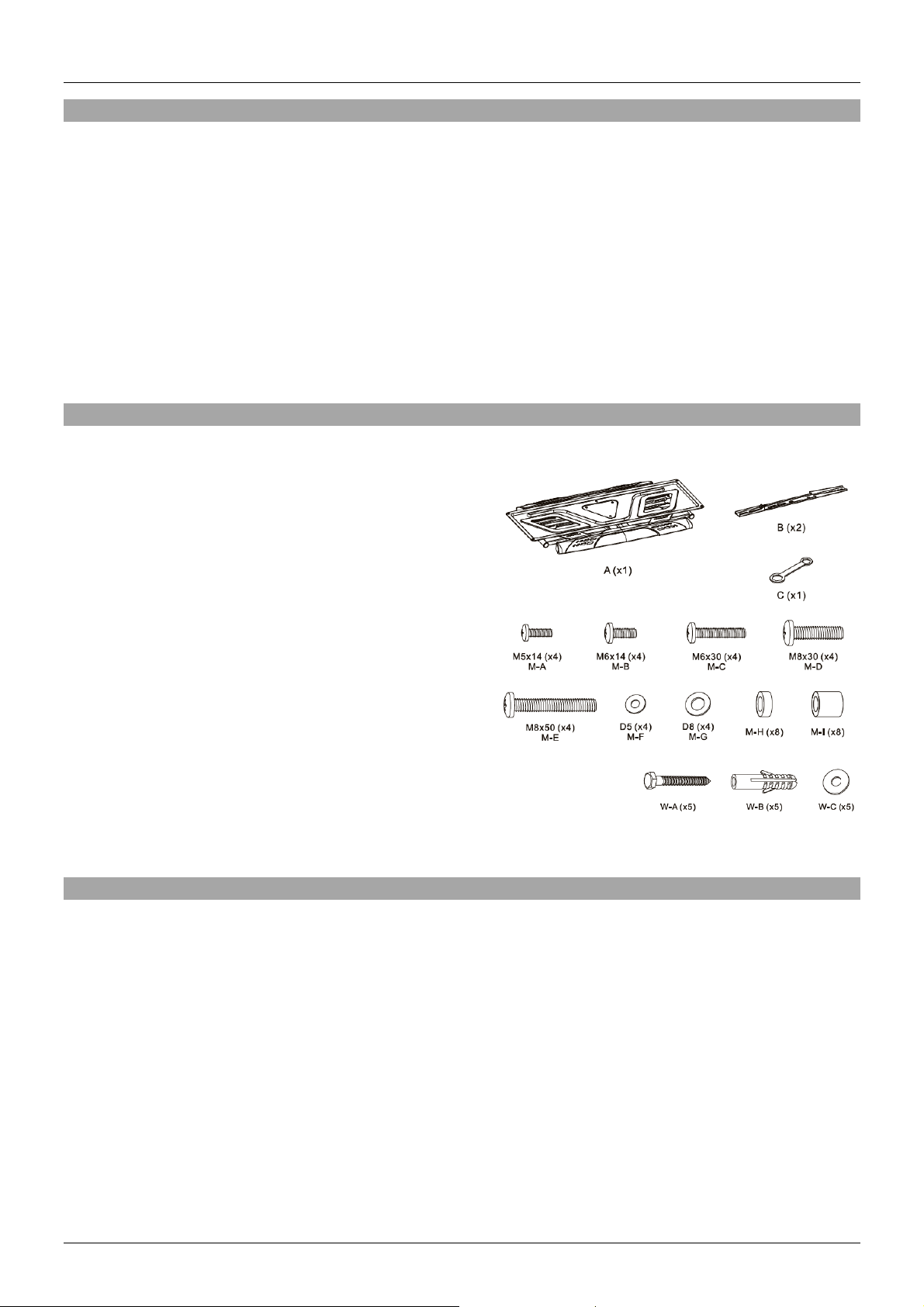
▪ Adjustable display wall plate with plastic covers
▪ 2 x Mounting brackets
▪ 1 x Spanner
▪ 4 x M5x14mm (M-A)
▪ 4 x M6x14mm (M-B)
▪ 4 x M6x30mm (M-C)
▪ 4 x M8x30mm (M-D)
▪ 4 x M8x50mm (M-E)
▪ 4 x Diameter 5mm Washer (M-F)
▪ 4 x Diameter 8mm Washer (M-G)
▪ 8 x Small Spacer (M-H)
▪ 8 x Large Spacer (M-I)
▪ 5 x Wall Screws (W-A)
▪ 5 x Wall Plugs (W-B)
▪ 5 x Washer (W-C)
▪ Lindy Manual
Specification
▪ Minimum Supported Display Size: 32"
▪ Maximum Supported Display Size: 70"
▪ Maximum Supported Weight: 45kg (99.21lb)
▪ VESA Compliance: 200x200, 300x200, 300x300, 400x200, 400x300, 400x400
▪ Tilt Adjustment: +7°~-15°
▪ Pivot Adjustment: +60°~-60°
▪ Screen Level:+3°~-3°
▪ Screen Distance from Wall: 41mm (1.61in)
▪ Cable Management: Yes
▪ Installation: Double Stud (406mm/450mm) or solid wall
▪ Material: Powdered coated steel with plastic covers
▪ Colour: Black
Page 4
User Manual English
Installation
Please follow all instructions below. All diagrams are labelled with the
required fixings.
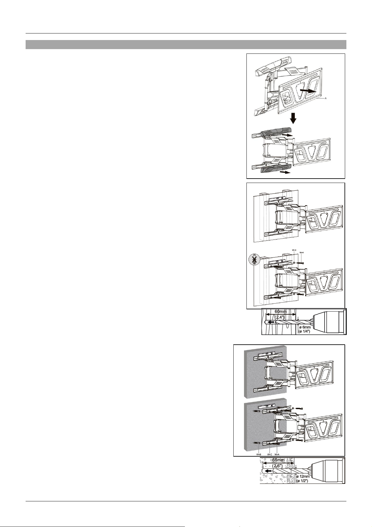
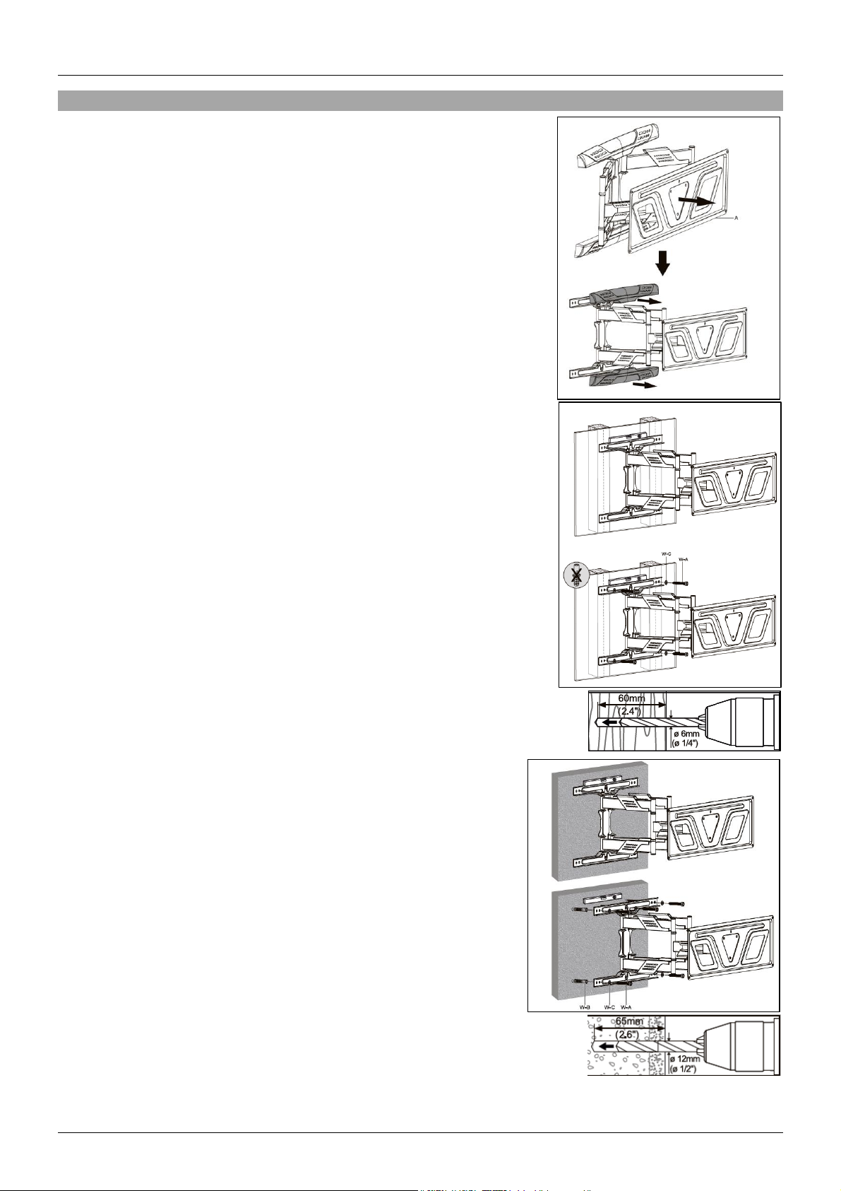
Pull out the main wall plate and remove the plastic covers.
Fixing display mount to a stud wall
Locate the studs behind the wall using a stud locator (not included).
Once located, position the display mount aligned with the studs. Use a
spirit level (not included) to ensure the mount is positioned correctly.
With a pencil (not included), mark clearly the location of the studs when
aligned with the holes of the display mount.
Once marked, drill 4 holes into the 4 markings of the studs (drill not
included). Suggested depths and drill bit size is here (Right). Reposition the mount, aligned with the drilled holes and secure the mount
to the wall using the included screws and washers (W-A) and (W-C).
Wall plugs are not required for this mounting surface.
Please see the diagram here (Right) for further explanation.
Fixing display to brick wall
Position the display mount onto the wall where required. Use a
spirit level (not included) to ensure the mount is positioned
correctly. With a pencil (not included), mark clearly the location of
the drilling points when aligned with the holes of the display mount.
Once marked, drill 4 holes into the 4 markings of on the wall (drill
not included). Suggested depths and drill bit sizing is here (Right).
Re-position the mount, aligned with the drilled holes and secure
the mount to the wall using the included screws, washers and wall
plugs: (W-A), (W-C) and (W-B).
Please see the diagram here (Right) for further explanation.
Page 5
User Manual English
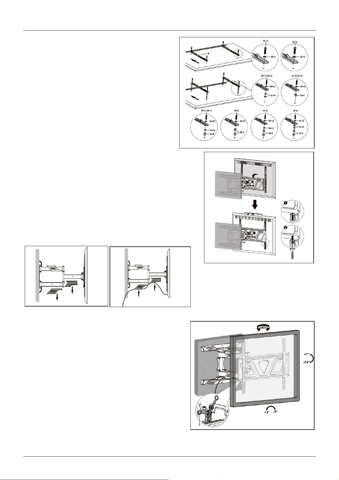
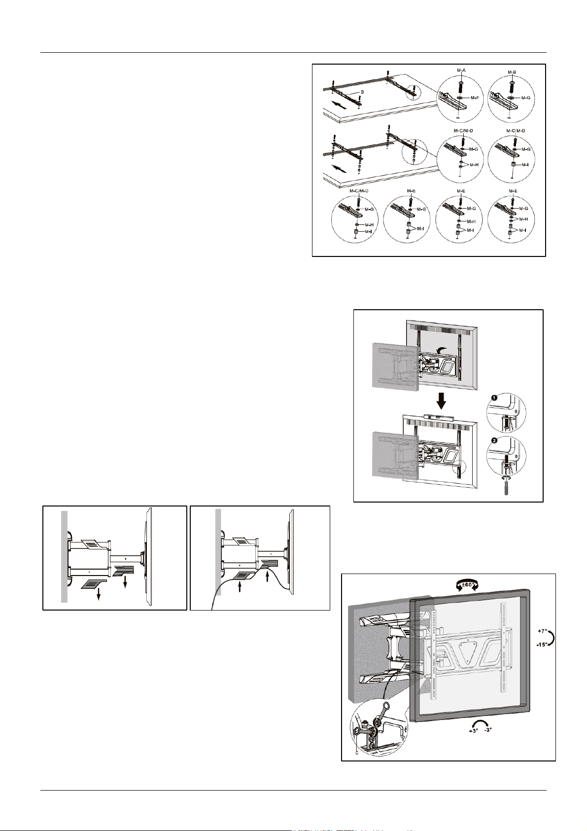
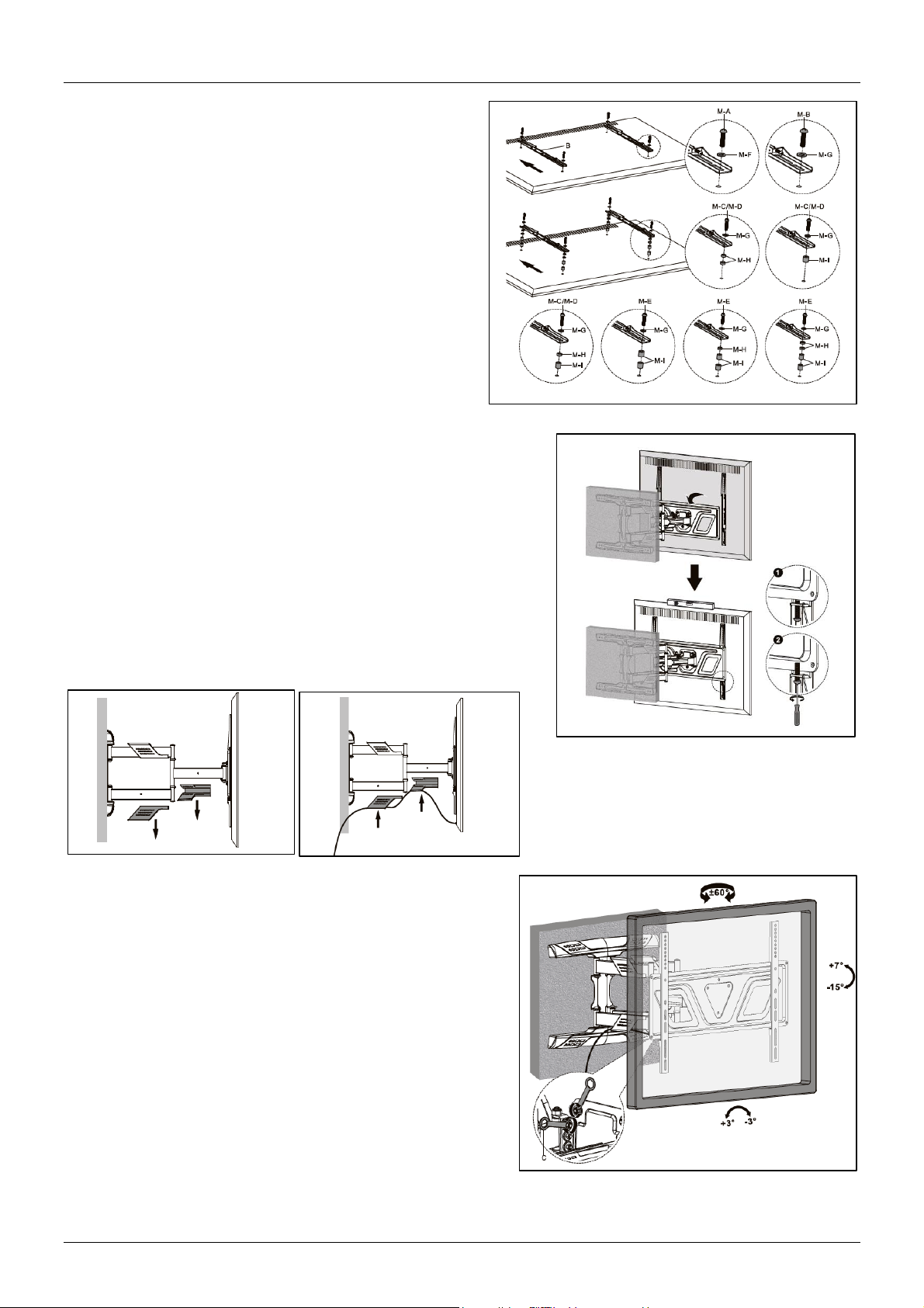
Re-attach the plastic covers to the mount to cover the
mounting points.
Mounting display brackets to the display
Align the left and right display brackets with the VESA
mounting holes of the display. Adjust these accordingly
to the desired height of the display when installed.
Secure into place using four of the included bolts and
washers. Tighten with a screwdriver (not included).
Please ensure the washers are used as without, the
bolts could damage the rear of the display. Add
spacers for displays with a recessed back or for access
to AV connections. Please ensure the correct fixings
are used as per the diagram here (right).
Mounting the display and brackets to the display plate
Fit the bracket and display to the display mount on the wall by
hooking into place. Please ensure another person can assist
with carrying the display and securing the brackets. Secure into
place by tightening the 2 screws into place as shown on the
diagram (Right).
The plastic covers shown here (left) can be
used to manage cables connected to the
display. Remove the covers, connect
relevant cables to the display and re-fit the
covers to the mount.
For manoeuvring the display when fitted, loosen the bolts
as shown slightly. Position the display and re-tighten the
bolts to secure the display.
Page 6
Benutzerhandbuch Deutsch
Einführung
Wir freuen uns, dass Ihre Wahl auf ein LINDY-Produkt gefallen ist und danken Ihnen für Ihr Vertrauen. Sie
können sich jederzeit auf unsere Produkte und einen guten Service verlassen. Diese Bewegliche DisplayWandhalterung unterliegt einer 2-Jahres LINDY Herstellergarantie und lebenslangem kostenlosen
technischen Support. Bitte lesen Sie diese Anleitung sorgfältig und bewahren Sie sie auf.
Die Lindy Bewegliche Display-Wandhalterung ist eine stabile Montagelösung zur sicheren Befestigung
eines Displays an einer Stein- oder Holzständerwand. Das flache, schlanke Design der Halterung sorgt
für einen bündigen Sitz des Displays und eine ästhetisch ansprechende Installation im privaten oder
professionellen Umfeld. Der bewegliche Arm ermöglicht einen einfachen Zugang zu den Anschlüssen an
der Rückseite des Displays. Für eine optimale Sicht kann das Display geschwenkt oder um 15° geneigt
werden.
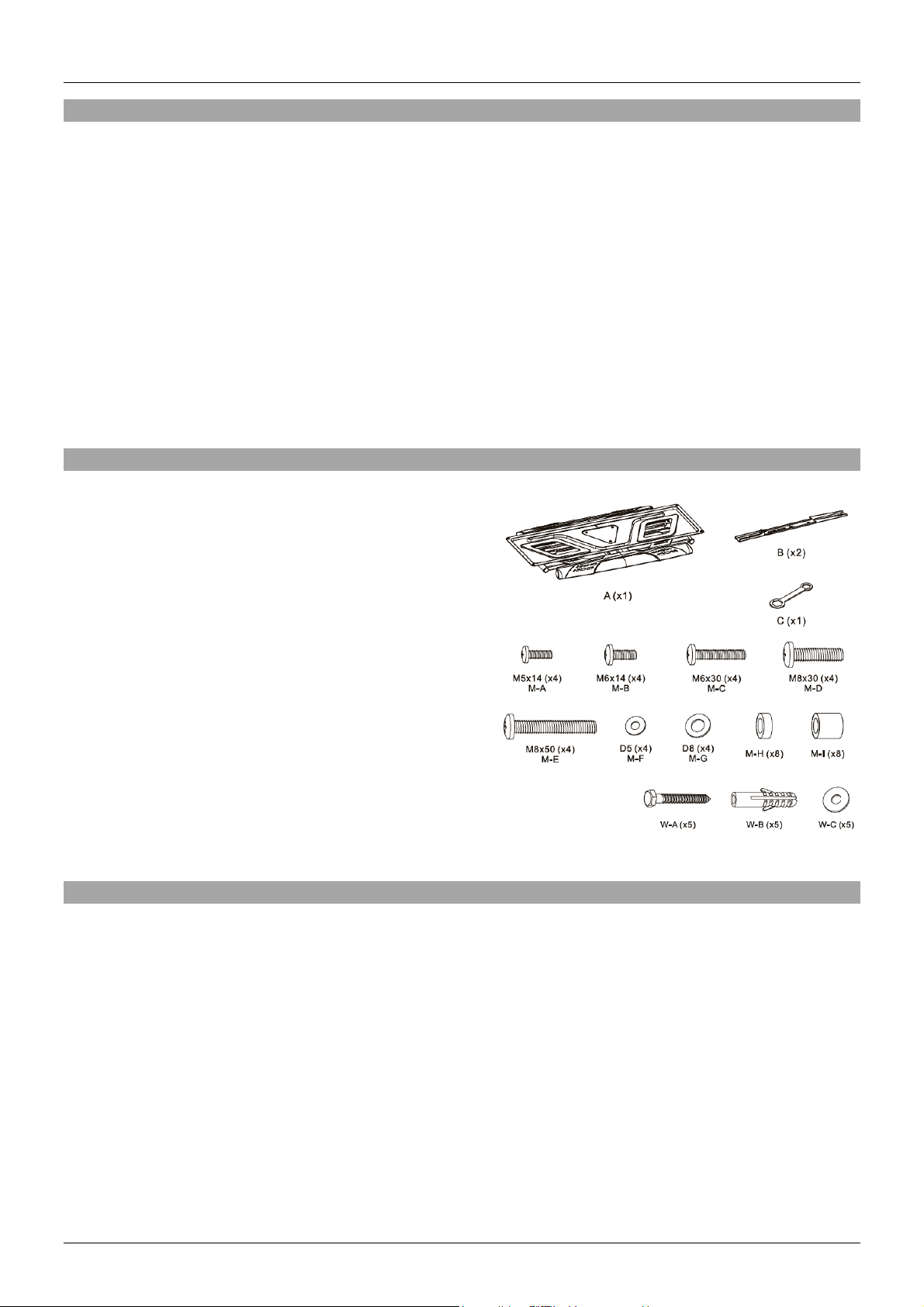
Lieferumfang
▪ Anpassbare Display-Wandhalterung mit Kunststoffabdeckung
▪ 2x Montagehalterung
▪ 1x Schraubenschlüssel
▪ 4 x M5x14mm (M-A)
▪ 4 x M6x14mm (M-B)
▪ 4 x M6x30mm (M-C)
▪ 4 x M8x30mm (M-D)
▪ 4 x M8x50mm (M-E)
▪ 4x 5mm-Unterlegscheibe (M-F)
▪ 4x 8mm-Unterlegscheibe (M-G)
▪ 8x Abstandhalter klein (M-H)
▪ 8x Abstandhalter groß (M-I)
▪ 5x Schrauben (W-A)
▪ 5x Dübel (W-B)
▪ 5x Unterlegscheibe (W-C)
▪ Lindy Handbuch
Spezifikationen
▪ Unterstützte Displaygröße (min.): 32”
▪ Unterstützte Displaygröße (max.): 70”
▪ Unterstütztes Gewicht: 45kg (99.21lb)
▪ VESA-Kompatibilität: 200x200, 300x200, 300x300, 400x200, 400x300, 400x400
▪ Neigungsbereich: +7°~-15°
▪ Schwenkungsbereich: +60°~-60°
▪ Ausrichtung des Bildschirms um ~3° nach oben oder unten möglich
▪ Abstand des Bildschirms von der Wand: 41mm (1.61in)
▪ Kabelmanagement: Ja
▪ Installation: Doppelständerwand (406mm/450mm) oder feste Wand
▪ Material: Pulverbeschichteter Stahl mit Kunststoffabdeckungen
▪ Farbe: Schwarz
Page 7
Benutzerhandbuch Deutsch
Installation
Bitte folgen Sie den nachstehenden Anweisungen. Alle Diagramme
zeigen die jeweils notwendigen Fixierungen.
Packen Sie die Haupt-Wandplatte aus und entfernen Sie die
Kunststoffabdeckungen.
Anbringen der Display-Wandhalterung an einer Ständerwand
Lokalisieren Sie die Balken in der Wand, nutzen Sie hierfür einen
Balkenfinder (nicht inklusive). Die Display-Halterung muss an den
Balken befestigt werden, richten Sie die Halterung entsprechend aus.
Nutzen Sie eine Wasserwaage (nicht inklusive), um sicherzustellen,
dass die Halterung korrekt positioniert ist. Verwenden Sie die
Wandhalterung als Schablone, um mit einem Stift (nicht inklusive) die
4 Bohrlöcher an der Wand zu markieren.
Bohren Sie die 4 angezeichneten Löcher (Bohrer nicht inklusive).
Empfehlungen zu Tiefe und Bohreinsatz-Größe finden Sie im
Diagramm rechts. Befestigen Sie die Wandhalterung mit den
beiliegenden Schrauben (W-A) und Unterlegscheiben (W-C). Für diese
Befestigungsoberfläche benötigen Sie keine Dübel.
Weitere Informationen bietet das Diagramm auf der rechten Seite.
Anbringen der Display-Wandhalterung an einer Steinwand
Positionieren Sie die Display-Wandhalterung an der gewünschten
Stelle an der Wand. Benutzen Sie eine Wasserwaage (nicht
inklusive), um sicherzustellen, dass die Halterung korrekt
positioniert ist. Nutzen Sie die Wandhalterung als Schablone, um
die 4 Bohrlöcher anzuzeichnen.
Bohren Sie die 4 angezeichneten Löcher (Bohrer nicht inklusive).
Empfehlungen zu Tiefe und Bohreinsatz-Größe finden Sie im
Diagramm rechts. Versenken Sie die beiliegenden Dübel (W-B) in
den Bohrlöchern. Nutzen Sie zur Befestigung der Wandhalterung
die beiliegenden Schrauben (W-A) und Unterlegscheiben (W-C). Das
Diagramm auf der rechten Seite bietet weitere Informationen.
Page 8
Benutzerhandbuch Deutsch
Bringen Sie die Kunststoffabdeckungen an der
Wandhalterung an, um die Befestigungspunkte
abzudecken.
Anbringen der Display-Halterung am Display
Richten Sie die linke und rechte Display-Halterung an
den VESA-Befestigungslöchern auf der Rückseite des
Displays aus. Passen Sie diese entsprechend der
gewünschten Höhe des Displays an. Montieren Sie die
Halterung mit vier der beiliegenden Schrauben und
passenden Unterlegscheiben. Ziehen Sie die
Schrauben mit einem Schraubendreher (nicht
inklusive) fest. Stellen Sie sicher, dass die
Unterlegscheiben benutzt werden, da die Schrauben ansonsten die Rückseite des Displays beschädigen
können. Fügen Sie Abstandshalter hinzu für Displays mit einer versetzen Rückwand oder für den Zugang
zu AV-Verbindungen. Stellen Sie sicher, dass die korrekten Fixierungen verwendet werden, wie im
Diagramm rechts gezeigt.
Anbringen des Displays an der Wandhalterung
Hängen Sie den Bildschirm mit den bereits montierten
Halterungen an die Wandhalterung. Bitte lassen Sie sich hierbei
von einer zweiten Person helfen das Display zu tragen und die
Halterung zu sichern. Sichern Sie das Ganze, indem Sie die
zwei Schrauben wie im Diagramm rechts dargestellt
festschrauben.
Die in der Abbildung (links) gezeigten
Plastikmuffen können zum Ordnen der an
das Display angeschlossenen Kabel
genutzt werden. Entfernen Sie die
Plastikmuffen, schließen Sie die benötigten Kabel an das
Display an und befestigen Sie die Plastikmuffen wieder an
der Halterung.
Zum Bewegen des Displays nach Befestigung lösen Sie die
Schraube etwas, wie in der Abbildung dargestellt. Bringen
Sie das Display in die gewünschte Position und ziehen Sie
die Schraube danach wieder fest, um das Display zu sichern.
Page 9
Manuel Utilisateur Français
Introduction
Nous sommes heureux que votre choix se soit porté sur un produit LINDY et vous remercions de votre
confiance. Vous pouvez compter à tout moment sur la qualité de nos produits et de notre service. Ce
support mural pour écran (Single Display Full Motion Wall Mount) est soumis à une durée de garantie
LINDY de 2 ans et d’une assistance technique gratuite à vie. Merci de lire attentivement ces instructions
et de les conserver pour future référence.
Le support mural pour écran pleine grandeur (Single Display Full Motion) est une solution sûre et de haute
qualité pour le montage d'un écran sur un mur plein ou à montants, avec la possibilité d'incliner librement
ou de déplacer l'écran horizontalement. Le support possède un profil mince, ce qui permet d'encastrer
l'écran dans la surface et d'assurer une mise en place esthétique dans les installations audiovisuelles
résidentielles ou professionnelles, tandis que le bras en porte-à-faux permet d'accéder facilement aux
connexions du panneau arrière. L'écran est facilement réglable horizontalement ou avec une inclinaison
de 15°, pour offrir une expérience visuelle des plus confortables.
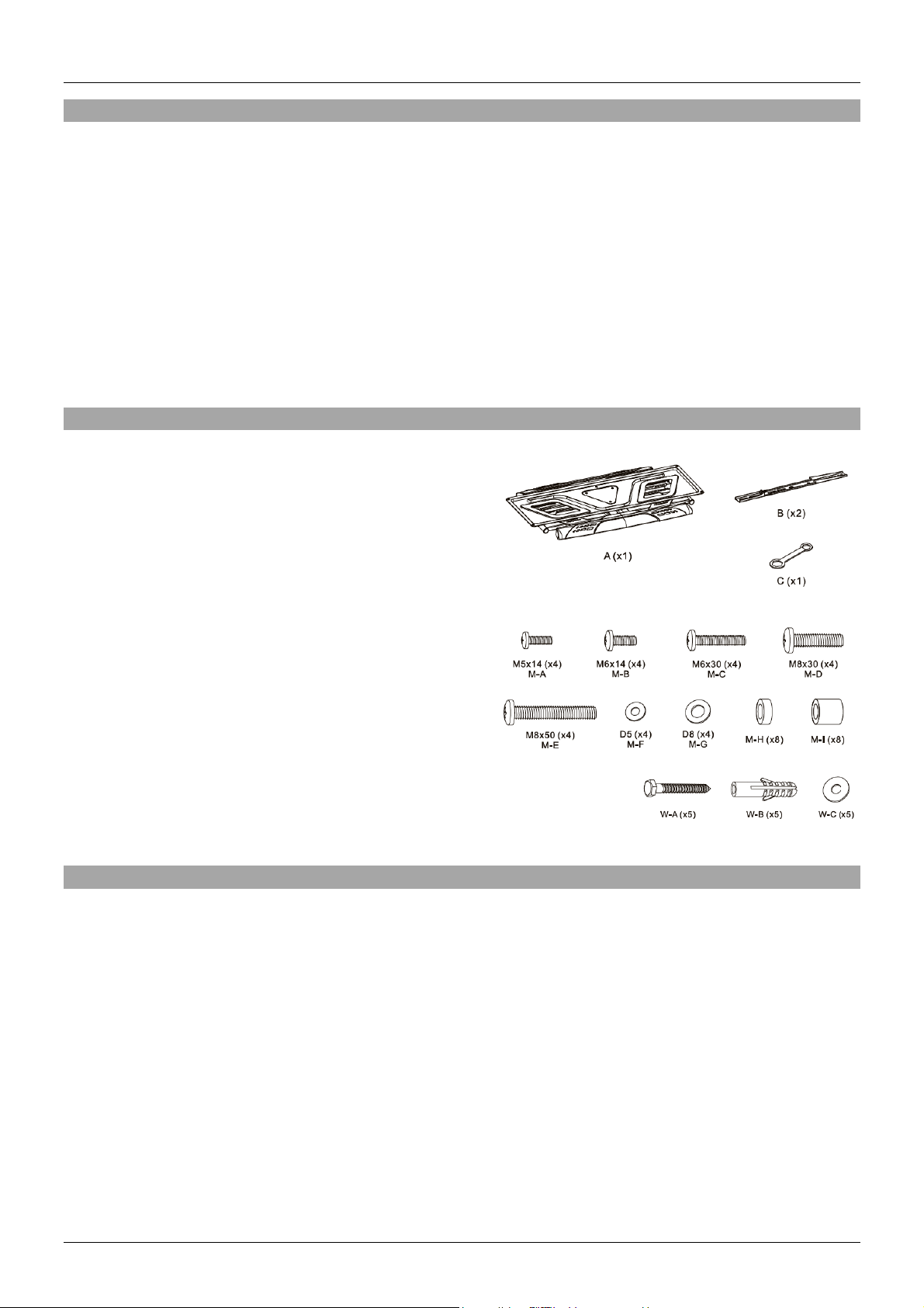
Contenu de l’emballage
▪ Support écran avec caches en matière plastique
▪ 2 x support de fixation
▪ 1 x clé plate
▪ 4 x M5x14mm (M-A)
▪ 4 x M6x14mm (M-B)
▪ 4 x M6x30mm (M-C)
▪ 4 x M8x30mm (M-D)
▪ 4 x M8x50mm (M-E)
▪ 4 x rondelle diamètre 5mm (M-F)
▪ 4 x rondelle diamètre 8mm (M-G)
▪ 8 x entretoise courte (M-H)
▪ 8 x entretoise large (M-I)
▪ 5 x vis de fixation au mur (W-A)
▪ 5 x chevilles plastique (W-B)
▪ 5 x rondelles (W-C)
▪ Manuel LINDY
Spécifications
▪ Taille d’écran minimale prise en charge: 32"
▪ Taille d’écran maximale prise en charge: 70"
▪ Poids maximum pris en charge: 45kg (99.21lb)
▪ Conformité VESA: 200x200, 300x200, 300x300, 400x200, 400x300, 400x400
▪ Ajustement de l’inclinaison: +7°~-15°
▪ Ajustement de la rotation: +60°~-60°
▪ Niveau de l’écran:+3°~-3°
▪ Distance de l’écran au mur: 41mm (1.61in)
▪ Gestion des câbles: Oui
▪ Installation: Double montant (406mm/450mm) ou mur plein
▪ Matériaux: acier revêtu de peinture poudre et capots en matière plastique
▪ Couleur: Noir
Page 10
Manuel Utilisateur Français
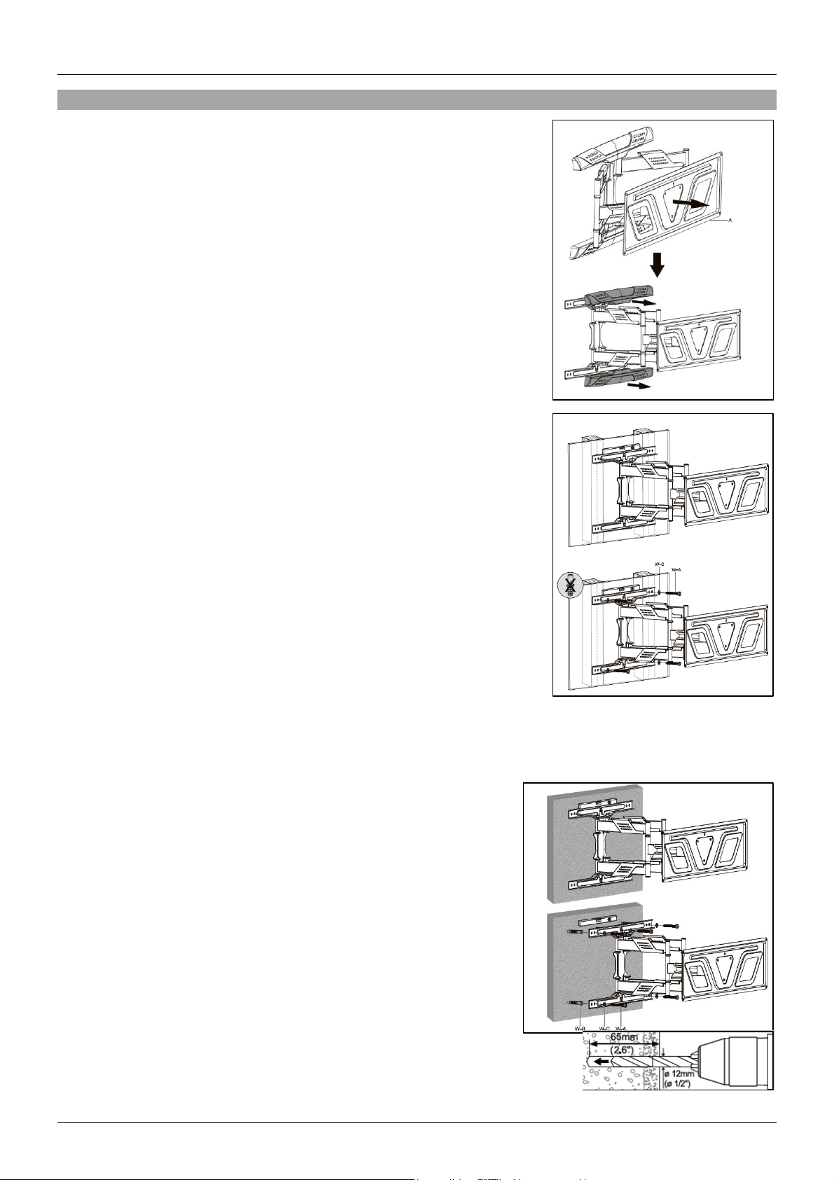
Installation
Veuillez suivre toutes les instructions ci-dessous. Tous les schémas
sont marqués avec les fixations requises.
Sortez la plaque murale principale et retirez les caches en matière
plastique.
Fixation du support d’écran sur un mur à montants
Localisez les montants derrière le mur à l'aide d'un détecteur de
montants (non inclus). Une fois localisé, positionnez le support
d'affichage aligné avec les montants. Utilisez un niveau à bulle (non
fourni) pour vous assurer que le support est correctement positionné.
À l'aide d'un crayon (non fourni), marquez clairement l'emplacement
des montants lorsqu'ils sont alignés avec les trous du support
d'affichage.
Une fois marqué, percez 4 trous dans les 4 marquages des montants
(perceuse non incluse). Les profondeurs et la taille des forets
suggérées sont ici (à droite). Repositionnez le support, aligné avec les
trous percés et fixez le support au mur à l'aide des vis et des rondelles
fournies (W-A) et (W-C). Les chevilles ne sont pas nécessaires pour
cette surface de montage.
Veuillez consulter le schéma ci-contre (à droite) pour plus
d'explications.
Fixation du support sur un mur plein
Positionnez le support d'affichage sur le mur à l'endroit voulu.
Utilisez un niveau à bulle (non fourni) pour vous assurer que le
support est correctement positionné. Avec un crayon (non fourni),
marquez clairement l'emplacement des points de perçage
lorsqu'ils sont alignés avec les trous du support d'affichage.
Une fois marqués, percez 4 trous dans les 4 marques du mur
(perceuse non incluse). Les profondeurs suggérées et la taille des
forets se trouvent ici (à droite). Repositionnez le support, aligné
avec les trous percés et fixez le support au mur à l'aide des vis,
rondelles et chevilles fournies : (W-A), (W-C) et (W-B).
Pour plus d'explications, veuillez consulter le schéma ci-contre (à
droite).
Remettez les capots en plastique sur le support pour couvrir les
points de montage.
Page 11
Manuel Utilisateur Français
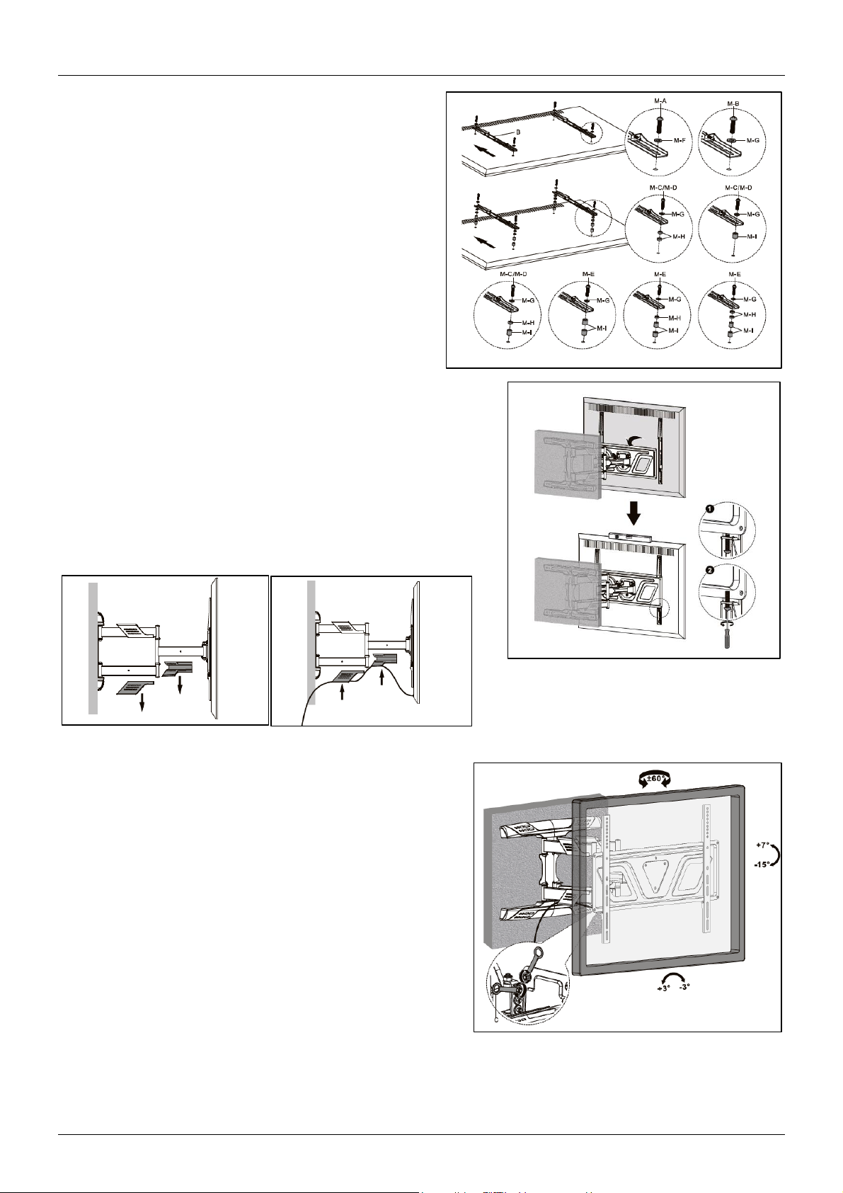
Fixation des supports à l’écran
Alignez les supports d'affichage gauche et droit avec
les trous de fixation VESA de l'affichage. Ajustez-les
en conséquence de la hauteur souhaitée de l'écran
lorsqu'il est installé. Fixez en place à l'aide de quatre
des boulons et des rondelles fournis. Serrez avec un
tournevis (non fourni). Veillez à utiliser les rondelles
car sans elles, les boulons pourraient endommager
l'arrière de l'écran. Ajoutez des entretoises pour les
écrans dont l'arrière est encastré ou pour accéder aux
connexions AV. Veuillez vous assurer que les fixations
correctes sont utilisées comme indiqué sur le schéma
ci-contre (à droite).
Montage de l’écran et des supports sur la plaque
d’écran
Fixez le support et l'écran au support d'affichage sur le mur en
les accrochant. Veuillez vous assurer qu'une autre personne
peut vous aider à porter le présentoir et à fixer les supports.
Fixez en place en serrant les 2 vis comme indiqué sur le
schéma (à droite).
Les capots en plastique illustrés ici (à
gauche) permettent de gérer les câbles
connectés à l'écran. Retirez-les, connectez
les câbles correspondants à l'écran et remettez les couvercles en place sur le support.
Pour manœuvrer l'écran une fois monté, desserrez
légèrement les boulons comme indiqué. Positionnez
l'écran et resserrez les boulons pour sécuriser l'écran.
Page 12
Manuale Italiano
Introduzione
Vi ringraziamo per aver acquistato il supporto per schermo a parete Full Motion. Questo prodotto è stato
progettato per garantirvi la massima affidabilità e semplicità di utilizzo ed è coperto da 2 anni di garanzia
LINDY oltre che da un servizio di supporto tecnico a vita. Per assicurarvi di farne un uso corretto vi
invitiamo a leggere attentamente questo manuale e a conservarlo per future consultazioni.
Questo supporto per schermo a parete Full Motion è una soluzione di alta qualità per il montaggio di un
singolo schermo su una parete a montanti o di mattoni, con la possibilità di inclinare e spostare
orizzontalmente il display. Il design low-profile molto sottile consente di tenere lo schermo molto vicino
alla superficie, l’ideale in installazioni AV professionali o domestiche, mentre il braccio a sbalzo consente
un semplice accesso alle connessioni sul retro. Il display è facilmente regolabile in orizzontale, o con
un'inclinazione di 15°, per offrire la più confortevole esperienza visiva.
Contenuto della confezione
▪ Placca di montaggio a parete con cover in plastica
▪ 2 x Staffa di montaggio
▪ 1 x Chiave inglese
▪ 4 x M5x14mm (M-A)
▪ 4 x M6x14mm (M-B)
▪ 4 x M6x30mm (M-C)
▪ 4 x M8x30mm (M-D)
▪ 4 x M8x50mm (M-E)
▪ 4 x Rondella con diametro 5mm (M-F)
▪ 4 x Rondella con diametro 8mm (M-G)
▪ 8 x Distanziale piccolo (M-H)
▪ 8 x Distanziale grande (M-I)
▪ 5 x Vite da parete (W-A)
▪ 5 x Spina da parete (W-B)
▪ 5 x Rondella (W-C)
▪ Manuale
Specifiche
▪ Grandezza minima Display: 32"
▪ Grandezza massima Display: 70"
▪ Peso Massimo supportato: 45kg (99.21lb)
▪ Compatibilità VESA: 200x200, 300x200, 300x300, 400x200, 400x300, 400x400
▪ Regolazione inclinazione: +7°~-15°
▪ Regolazione perno: +60°~-60°
▪ Livello schermo: +3°~-3°
▪ Distanza dello schermo dalla parete: 41mm (1.61in)
▪ Cable Management: Sì
▪ Installazione: doppio montante (406mm/450mm) o muro pieno
▪ Materiale: acciaio verniciato a polvere con cover in plastica
▪ Colore: nero
Page 13
Manuale Italiano
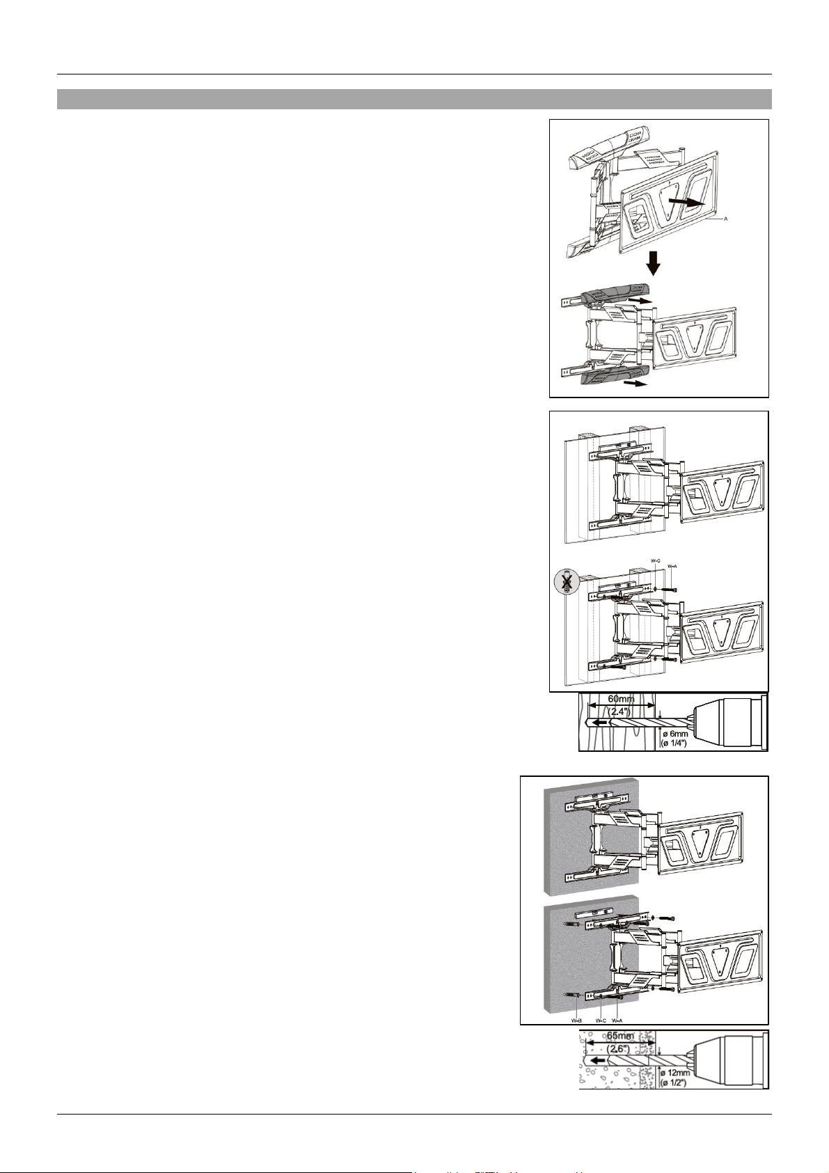
Installazione
Seguire le seguenti istruzioni per l’installazione. Tutti i diagrammi sono
etichettati con le componenti richieste.
Estrarre la piastra principale della parete e rimuovere le cover in
plastica.
Fissare il supporto ad un muro a montanti
Individuare i montanti dietro la parete utilizzando un localizzatore (non
incluso). Una volta individuati, posizionare il supporto del display
allineato con le viti prigioniere. Utilizzare una livella a bolla d'aria (non
inclusa) per verificare che il supporto sia posizionato correttamente.
Con una matita (non inclusa), segnare chiaramente la posizione dei
prigionieri una volta allineati con i fori del supporto del display.
Una volta marcati, praticare 4 fori nei 4 segni (trapano non incluso). Le
profondità consigliate e le dimensioni della punta sono mostrate qui (a
destra). Riposizionare il supporto, allinearlo ai fori praticati e fissarlo
alla parete con viti e rondelle (W-A) e (W-C) in dotazione. I tasselli a
muro non sono necessari per questa superficie di montaggio.
Consultare i diagrammi sulla destra per ulteriori informazioni.
Fissare il supporto ad un muro di mattoni
Posizionare il supporto del display sulla parete nel punto
desiderato. Utilizzare una livella a bolla d'aria (non inclusa) per
verificare che il supporto sia posizionato correttamente. Con una
matita (non inclusa), segnare chiaramente la posizione dei
prigionieri una volta allineati con i fori del supporto del display.
Una volta marcati, praticare 4 fori nei 4 segni (trapano non incluso).
Le profondità consigliate e le dimensioni della punta sono mostrate
qui (a destra). Riposizionare il supporto, allinearlo ai fori praticati e
fissarlo alla parete con viti, rondelle e tasselli a muro inclusi: (WA), (W-C) e (W-B).
Consultare i diagrammi sulla destra per ulteriori informazioni.
Page 14
Manuale Italiano
Riattaccare le cover in plastica al supporto.
Montaggio delle staffe sul display
Allineare le staffe del display a sinistra e a destra con
i fori di montaggio VESA del display. Regolarli di
conseguenza all'altezza desiderata del display al
momento dell'installazione. Fissare in posizione
utilizzando quattro dei bulloni e delle rondelle
rettangolari in dotazione. Serrare con un cacciavite
(non incluso). Utilizzare le rondelle poiché senza, i
bulloni rischiano di danneggiare la parte posteriore del
display. Aggiungere i distanziali per i display con il
retro incassato o per l'accesso alle connessioni AV.
Consultare i diagrammi sulla destra per assicurarsi di
usare gli accessori corretti.
Montaggio display e staffe sul supporto
Montare la staffa e il display sul supporto a parete
agganciandolo in posizione. Assicurarsi che un'altra persona
possa aiutare a trasportare il display e a fissare le staffe. Fissare
in posizione serrando le 2 viti come mostrato nella figura (a
destra).
Le cover in plastica mostrate nella figura a
fianco possono essere usate per farci
passare i cavi del display. Rimuovere le
cover, collegare i cavi al display e rifissare
le cover.
Per regolare il posizionamento del display una volta
fissato, allentare i bulloni come mostrato in figura.
Posizionare il display e serrare nuovamente i bulloni per
fissare il display.
Page 15

LINDY Herstellergarantie – Hinweis für Kunden in Deutschland
LINDY gewährt für dieses Produkt über die gesetzliche Regelung in Deutschland hinaus eine zweijährige Herstellergarantie ab Kaufdatum. Die detaillierten Bedingungen dieser Garantie finden Sie auf der LINDY Website aufgelistet
bei den AGBs.
Hersteller / Manufacturer (EU):. Manufacturer (UK):
LINDY-Elektronik GmbH LINDY Electronics Ltd
Markircher Str. 20 Sadler Forster Way
68229 Mannheim Stockton-on-Tees, TS17 9JY
Germany England
Email: [email protected] , T: +49 (0)621 470050 [email protected] , T: +44 (0)1642 754000
No. 40973
1st Edition, May 2020
lindy.com
 Loading...