

Page 1

Tested to comply with FCC Standards FOR COMMERCIAL USE ONLY!
KVM Extender DVI & USB 2.0 English Manual
This manual covers the DVI & USB 2.0 KVM Extender family:
Transmitters (TX)
39200: DVI & USB 2.0 Transmitter with HDMI connectors
39210: DVI & USB 2.0 Transmitter with DVI connectors
39240: DVI & USB 2.0 Transmitter with DVI connectors and
Fiber Optic connection
39201: RX with HDMI connectors, USB 2.0 without
39202: RX with HDMI connectors, USB 2.0 with Storage
39211: RX with DVI connectors, USB 2.0 without Storage
39212: RX with DVI connectors, USB 2.0 with Storage
39213: RX with DVI connectors, USB 2.0 without Storage,
39214: RX with DVI connectors, USB 2.0 with Storage and
39240: RX with DVI connectors, USB 2.0 without Storage,
Receivers (RX)
Storage
with Audio Option
Audio Option
with Fiber Optic connection
As well as all further models under special make numbers with activated options and combination of options
No. 39200 - 39202, 39210 - 39214, 39240, 39241 © LINDY – Fifth Issue (SEP 2015) 1
Page 2
1x Transmitter (TX)
1x power supply incl. 4 adapters
1x DVI-HDMI respectively DVI-DVI cable, 2m
1x USB cable A/B, 2m
4x housing feet
2x self-adhesive hook and loop pad
Manuals (DE, EN, FR, IT)
1x Receiver (RX)
1x power supply incl. 4 adapters
1x DVI-HDMI respectively DVI-DVI cable, 2m
4x housing feet
2x self-adhesive hook and loop pad
Manuals (DE, EN, FR, IT)
Introduction and Features
This KVM extender allows you to connect consoles to computers via a distance of up to 130m for direct Cat.6
cable connection, or up to 200m via a gigabit network switch, or up to 500m/20km via fibre optic modules
Multi/Single Mode. The KVM signals are transmitted either via Cat.6 or via Duplex LC cables. The Extender
uses digital transmission ensuring there is no signal degradation as is typically experienced when using KVM
extenders for analogue VGA signals.
This extender family supports digital DVI-D Single Link signals up to 1920x1200. For reasons of space, the
Extenders 39200 - 39202 use HDMI receptacles, but HDMI features such as audio, HDCP, YUV/YCbCr,
deep colour are NOT supported.
This extender family supports almost all USB 1.1/2.0 devices, but USB flash drives and USB hard drive
enclosures are supported only by extender versions with Mass Storage support - this option can be upgraded
if required via paid unlock code (SN based) - please contact LINDY support. LINDY support also can provide
additional information for various mounting kits.
For the whole extender product family the following additional features can be upgraded via SN-related paid
unlock code (combinations of unlocks are also possible):
Mass Storage option, analogue audio option*, VGA option*, RS232 option*, matrix switching option.
* marked options are only available for models with DVI ports!
The matrix switching option introduced in 2015 requires the connection of all extender boxes via one Gigabit
switch. Each KVM connection requires 1Gbit/s bandwidth! Therefore switches cannot be cascaded, or they
require at least a 10Gbit/s. connection. Therefore as also for security reasons the KVM network must be
always separated.
Options must be purchased exclusively for the receiver and will automatically become available on the
connected transmitter. The VGA option allows the feeding of VGA sources, VGA signals are digitized and
transmitted and output as digital DVI-D signals from the receiver. Back conversion back to VGA requires an
additional external converter. In a Matrix Switching network options must be purchased for all receiver units.
In the versions with fibre optic connection the SFP module can be replaced against a single mode version
for distances up to 20 km.
Packaging Content TX and RX
Installation, Operation
The KVM extender basically consists of a transmitter (TX) and receiver (RX). The TX (see product label or
imprint local / pc on the front panel) connects the computer or the DVI signal source to the KVM extender by
enclosed monitor and USB cables. The RX provides a bypass port for a local monitor.
The RX (see product label or imprint remote / mon on the front panel) connects to the user console, the
monitor by the enclosed monitor cable. The RX supports direct connection of 4 USB devices and/or USB
hubs as well.
If you want to secure the transmitter and receiver to prevent slipping, attach the self-adhesive hook and loop
pads (enclosed) to the underside of the device. Accessories like mounting brackets, DIN rail, as well as a 19
inch rack mount shelves are available on option – please contact LINDY support.
Dieses Produkt unterliegt kontinuierlicher technologischer Weiterentwicklung.
Das OSD und die Funktionalität kann von der hier beschriebenen leicht abweichen 2
Page 3
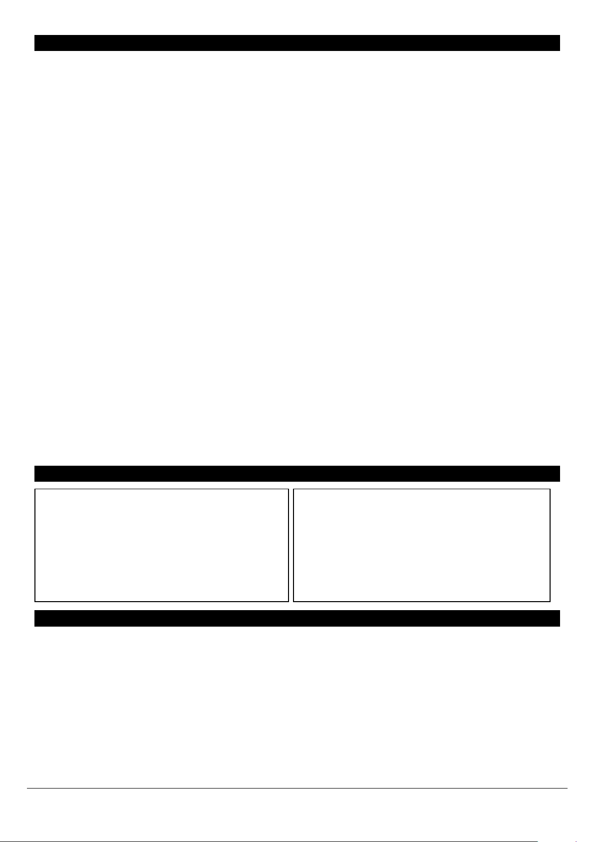
staus
link
video
RED
X X ORANGE
X
GREEN
The transmitter and receiver are connected with shielded Cat.5e/6/7 or LC-duplex cables. To achieve
maximum distances using cat. 6/7 direct connection please use high-quality solid core CAT 6 or higher cable,
E.g. LINDY no. 12047 / 12048.
Connect the power supply and switch on all devices. After connecting or
turning on, the transmitter and receiver automatically perform a cable or
connection test and calibration for approximately 5-10 seconds. During this
process the status LED on the front panel will flash different colours; the
meaning also is printed on the front panel.
When using HDMI monitors and HDMI/DP graphic cards colour distortions may occur because the EDID
signal of the monitor is forwarded by the Extender. In this case, set the graphics output to RGB signal, max.
32 bit or 8 bit colour depth, without HDCP. Or use a DVI output on the graphic card. Alternatively the DDC
settings of the extender can be set to a fixed preset value – see further below.
USB connections are hot pluggable. It is normal that after plugging a USB device this must be first recognized
and re-loaded. Via the Extender, a slightly larger amount of time is required for this than for direct computer
connections.
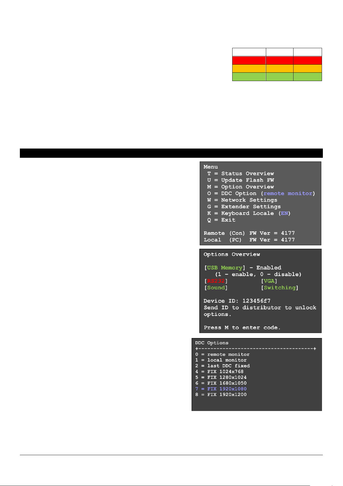
On Screen Menu
In the on screen menu device settings can be configured and
displayed. It also is used to update the firmware as well as for
activation of fee-based upgrade options like mass storage,
audio, VGA, RS232, and the switching option.
By security reason (configurable setting) the on screen menu
can be accessed only in the first few minutes after switching
on the Extender. To access the OSD the "Scroll Lock" key on
the keyboard must be pressed 5 times in quick succession. If
the OSD does not appear because the lock function is already
active, turn the Extender off/on and try again.
Menu item "U" is used to perform a firmware update. The
firmware is available on request at the LINDY tech support.
Menu item "M" indicates the installed options. The USB mass
storage support may temporarily be switched off if installed. To
change the options, you must purchase a fee-based activation
code dependent on the device ID for each RX. Note the device
ID displayed in the menu and contact LINDY support. This
activation code can be entered after entering the command "M"
in this menu.
Menu item "O" adjusts the treatment of the DDC/EDID
data. 0 or 1 defines to use the data of either the remote or
local monitor; the other settings define to use preset
EDID/DDC and resolutions.
Menu item "W" - network settings: refer to the switching
section.
Sub-menu item "K" - keyboard language. Currently, the
language layout can be selected between German, English,
French. Swiss and Italian may be added in the future.
This product is subject to continuous technological development.
The OSD and the functionality may differ slightly from the one described here 3
Page 4

Menu item "G" - Extender settings: this menu leads to
another further submenu of other settings:
Sub-menu item "V" - VGA digitization settings. When the
VGA option is enabled a VGA input signal can be digitized
automatically and manually. The M command toggles
between Auto-detect / DVI / VGA. The K command allows
the manual VGA fine tuning using the keys F1 through F8.
During manual adjustment the space bar changes the rate
of change cyclically.
I button restores the default settings.
Sub-menu item "A" - amplification of the audio input on the
remote unit. The default is 5, 0 turns off the input signal, 9 is the
maximum gain.
Sub-menu item "R" - RS232 settings. The D9 interface
assignment is as follows: pin 3 transmit data, 2 receive data, 4 DTR,
8 CTS. The universal rate of 9600 transfers all RS232 transparent
configurations. The following settings are available: baud rate: 4800,
9600, 19200, 38400, 57600, 115200, 230400; Parity: No, odd, even,
mark, space; Stop bits: 1, 2.
Sub-menu item "S" - show last image. When this function is enabled the Extender shows the last
transmitted frame before a connection was aborted instead of a black screen. The screen then is marked
with red flashing frame.
Submenu item "I" - Monitor sync. Synchronizes the image refresh rate of monitor with graphics card, what
can be useful for multimedia content. Because not all monitors support this function the default setting is off.
A flickering monitor is an indication that he does not support this function.
Sub-menu item "L" - lock menu. Here, it can be set whether or not
the access to the OSD 5 minutes after switching on is blocked.
Sub-menu item "P" - Power save menu. Here, the behaviour of
the monitor power save mode is set. If the Extender receives no
video signal it can also turn off its output signal so that the connected
monitor also switches to power save.
Sub-menu item "N" - noise filter. Here, an image enhancement
for content with very high dynamics (video with very rapid image
changes or noise) can be set. If for such signals the frame rate drops
below a critical limit a noise filter can improve the image transfer. It
should only be enabled together with the monitor sync option above and not without real need.
Sub-menu 'Q' - exits the sub-menu.
This product is subject to continuous technological development.
The OSD and the functionality may differ slightly from the one described here 4
Page 5

Network and Matrix Switching Menu and Options
The matrix KVM Switching option has been added to this KVM extender series in 2015. It is available as a
fee-based option and is activated via an unlock code. Older extender boxes require an additional firmware
update to enable their switching option. In a Matrix switching network the options must be purchased and
installed on all RX units. The RS232 option requires special hardware in order to function.
Main menu item "W" - network settings provides access to the advanced menus to configure the network
and switching options. Please note that this menu item is only active when the Switching Option has been
unlocked on the RX. In order to prevent unauthorized access to the Network Settings this menu is protected
by password. Access is only allowed for users with administrator rights. The factory settings provide an
administrator user with User: admin and Password: admin. Please change at least the password and record
the new settings in a secure place.
Sub-menu item "R" – sets all settings to factory default,
also all user, console and computer settings will be deleted.
Sub-menu item "P" – turn on the password system for
users and groups, see further below. This password system
is different and independent from the password access to
the network settings.
Sub-menu item "T" – Timeout settings, the following
options are available:
I – Immediately – enables password security to every switch, activated without reboot.
N – Never – password is required only after logout.
T – Time in minutes – time period with inactivity for automatic logout
Sub-menu item "C" – Auto-Connect. Available only if the password system is disabled: switches to the next
free port/computer if the KVM connection is separated by another user.
Sub-menu item "V" – Private Connection. To prevent the takeover of the connection by other users. To
enable this feature the SHIFT key (uppercase) must be pressed when establishing the connection (via OSD
or hotkey).
Sub-menu item "B" – User–PC binding. Upon activation, the switch network introduces restrictions for
standard users. Each console shows the password login screen. The admin has to assign a computer to
every user. After login users are automatically connected to their assigned computer, they cannot switch to
other computers. A user may log out with CTRL-ALT-F11. Only master and admin accounts can also access
other computers.
Sub-menu item "D" – Disconnect on Power Down / Switch off. Enabled: If a computer is switched off, also
the KVM connection the TX unit is disconnected.
Sub-menu item "M" – Master View – Network configuration. Admin console to manage the users, consoles
and computers. The following menu items are accessible only for the master:
Master View Menu "C" – Connections Overview. Shows the
existing connections and the free consoles and computers.
Connections can be interrupted or assigned as well.
This product is subject to continuous technological development.
The OSD and the functionality may differ slightly from the one described here 5
Page 6

Master View Menu "U" – User List. Administration of users and user groups.
User: Define a login name and password up to 16 characters.
Full Name: assigns the full name of the user. This full name is shown to other users, when this user interrupts
their connection.
Password: required for login, max. 16 characters
Rights – there are 3 kinds of rights: User, Master and Admin. By pressing the + key the rights are toggled.
Admin can interrupt the connection of master and user. If an admin interrupts the connection of another
Admin, the latter can retrieve the connection. Private connections cannot be interrupted.
Master can interrupt the connections of users. If a master
breaks the connection of another master, the latter can
retrieve the connection. Admin, master and private
connections cannot be interrupted.
User: If a user disconnects another user’s connection,
the latter can retrieve the connection. Admin and private
connections cannot be interrupted.
Groups: Each user can be assigned to one of 8 user
groups. Each computer is also assigned to a user group.
By default, all computers arr in the same group. The user
assignment to a group is done by entering the digit 1 to 8.
Bound PC: If the User-PC binding is active (see above: sub-menu item "B") each user must have a PC
assigned. In the user details menu the computer selection menu can be displayed by pressing the RETURN
key.
Master View Menu "W" – Console Extender List.
Shows the console list with all connections.
„this“ shows the connection of the own console.
„in use“ shows an active connection of another console.
„free“ shows that the console is not connected to a
computer/TX.
A name can be assigned to each console.
This product is subject to continuous technological development.
The OSD and the functionality may differ slightly from the one described here 6
Page 7

Master View Menu "S" – Computer Extender List.
Shows all computers in the system and their group
assignment and status. Also here a name can be given
via the Info menu, the group assignment is done by
entering the numbers 1 to 8.
Master View Menu "H" – Multi-Head Configuration
If you use multiple monitors per computer each graphic
channel and each monitor requires individual Extender
boxes that have to be grouped in the Extender OSD
menu via multi head configuration. To simplify the
mapping individual names should be assigned to the
console and computer boxes. To assist in the name
assignment, the LED on each Extender box is flashing
red/green if it is just configured. It may be helpful to
connect all Extender boxes to a switch locally in one
place to configure the network. In this case you only need
one console to configure all Extender boxes.
Open the multi-head configuration menu and create a
new MULTI-HEAD SET for each computer and for each
console by pressing the A button. In the submenu multihead detail, you can configure the individual multi-head
configuration settings by selecting the corresponding
boxes. The type is detected automatically after
establishing the first connection.
To leave this menu and save settings press the Q.
The details menu can always be brought up by pressing I in the main Multi-Head menu. By pressing R you
can remove an extender from the Multi-Head set.
Multi-Head Set connections are always switched together in combination.
This product is subject to continuous technological development.
The OSD and the functionality may differ slightly from the one described here 7
Page 8

CE Declaration of Conformity
This equipment complies with the requirements relating to Electromagnetic Compatibility Standards EN55022/EN55024 and the further
standards cited therein. It must be used with shielded cables only.
It has been manufactured under the scope of RoHS compliance.
WEEE (Waste of Electrical and Electronic Equipment), Recycling of electronic products
In 2006 the European Union introduced regulations (WEEE) for the collection and recycling of all waste electrical and electronic equipment. It is
no longer allowable to simply throw away electrical and electronic equipment. Instead, these products must enter the recycling process.
Each individual EU member state has implemented the WEEE regulations into national law in slightly different ways. Please follow your
national law when you want to dispose of any electrical or electronic products. More details can be obtained from your national WEEE recycling
Matrix Switching via OSD and Hotkey
The KVM Switching OSD is invoked by the hotkey
CTRL+ALT+F12.
It lists all computers and their status in the switching
network.
In BLUE the recently connected computer is listed.
In White the other computers with connection to a
console are listed.
In Green powered computers without connection to
a console are listed.
In Red computers / RX boxes are listed that once have been connected but are not available
recently. If required, these entries can be deleted by pressing the DELETE key.
Select a computer ( > ) by cursor keys up / down, the RETURN key switches to the selected
computer. The order (line number) of the computers in the menu can be changed by typing the
desired number in a row and the list will be reorganized.
The hotkey combination CTRL+ALT+F4 switches to computer no. 4 in the list.
If the password system is active the user will be displayed in the OSD at the bottom.
The key X logs out, the key D interrupts the recent connection to the selected computer.
Trouble shooting
If you cannot solve problems with this Extender please contact our support. You can reach us worldwide at
the numbers listed on our website. Or send us an email to support@lindy.com.
Legal Information
Hersteller / Manufacturer (EU): LINDY Electronics Ltd.
LINDY-Elektronik GmbH Sadler Forster Way
Markircher Str. 20 Teesside Industrial Estate, Thornaby
68229 Mannheim Stockton-on-Tees, TS17 9JY
GERMANY United Kingdom
Email: info@lindy.com , T: 0049 (0)621 470050 postmaster@lindy.co.uk , T: +44 (0) 1642 754000
This product is subject to continuous technological development.
The OSD and the functionality may differ slightly from the one described here 8
 Loading...