

Page 1
Tested to Comply with
FCC Standards
For Home and Office Use!
C6 HDMI & VGA Switching Extender
Transmitter, 100m
User Manual English
Benutzerhandbuch Deutsch
Manuel Utilisateur Français
Manuale Italiano
No. 38215
www.lindy.com
© LINDY ELECTRONICS LIMITED & LINDY-ELEKTRONIK GMBH - SECOND EDITION (April 2016)
Page 2

!!! IMPORTANT !!!
Only use a direct Cat.5e/6/7 cable connection between the
HDBaseT ports. Do not connect these ports to Network or
Ethernet equipment or any active components
!!!! WICHTIG !!!!
Verwenden Sie AUSSCHLIEßLICH eine direkte
Kabelverbindung zwischen den HDBaseT Anschlüssen
aber NIEMALS eine Netzwerkverbindung oder Ethernet
oder irgendwelche aktiven Komponenten
!!! ATTENTION !!!
N'utilisez qu'une connexion par câble Ethernet directe
entre les ports, sans passer par le réseau Ethernet, un
commutateur ou un quelconque périphérique connecté à
votre réseau !
!!! IMPORTANTE !!!
UTILIZZATE UN CAVO DEDICATO PER LA CONNESSIONE
TRA LE DUE UNITA', NON COLLEGATELO AD UNA RETE
ETHERNET O AD ALTRI COMPONENTI ATTIVI
Page 3

User Manual English
Introduction
Thank you for purchasing the LINDY C6 HDMI & VGA Switching Extender Transmitter. Using
HDBaseTTM Technology this Transmitter allows you to send HDMI or VGA with Analogue Audio,
Ethernet, RS-232, and IR signals up to 100m using a single high quality Cat.6/Cat.7 RJ45 cable to an
HDBaseT Receiver or Display/Projector with integrated HDBaseT technology. Switching between the
HDMI and VGA inputs is quick and easy and can be completed by push button, IR remote control or RS232 command, perfect for integration in to a meeting room, classroom or control centre.
For added convenience and to enable discreet installation of a Receiver unit the Transmitter supports
24V PoH (Power over HDBaseT) allowing a single power supply to be used with the Transmitter to
power both units. For best results and especially longer distances, we recommend using solid
core/structured cabling.
Package Contents
C6 HDMI & VGA Switching Extender Transmitter
24V Power Adapter
C13 Mains Power Cable
IR Extender Cable 1.4m x 2
IR Remote Control
This User Manual
Features
Extends uncompressed HDMI/VGA signals up to 100m using HDBaseT Technology
For use with HDBaseT equipped displays, projectors and receivers
Use a single cable to extend HDMI, VGA, RS-232, IR, Ethernet and Audio Signals
Integrated Power over HDBaseT (24V PoH) functionality for use with compatible HDBaseT receivers
Designed for use with Lecture Hall, Classroom, Showroom, professional HDTV installations,
Multimedia and Control Centre system installations
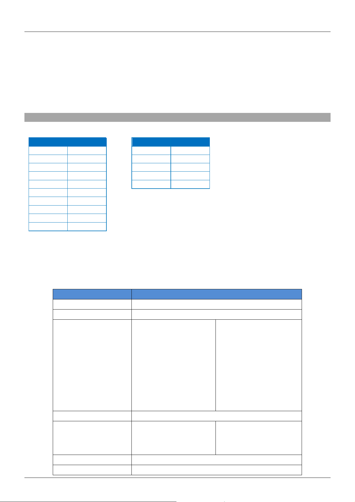
Specification
Accepts HDMI & VGA Inputs and extends selected input up to 100m
Controlled via IR Remote, OSD or RS232
Extends HDMI 1.4, HDCP, VGA, 10/100 Ethernet, RS-232 & IR up to 100m via HDBaseT technology
Connection is via CAT5e (up to 80m) or CAT6/7 cable (up to 100m)
Power-over-HDBaseT (24V PoH) function for use with compatible receivers
HDTV resolutions: 1080p24/30/50/60, 1080i, 720p, 576p & 480p
PC resolutions: From 640x480 to 1920x1200 RB
Built in scaling function, from 480-1080p, including Over/Under/Pan/Full Scan
Deep Colour capable: supports 30/36 bit colour depth
Audio Formats: LPCM, DTS Digital, DTS HD, Dolby Digital & Dolby True HD
Control of IR (33-50kHz) equipment via the extender
Adjustable Hue, Saturation and Sharpness
Ports: HDMI In, VGA In, 3.5mm Stereo Audio In, RJ45 HDBaseT Out, 1 x Ethernet RJ45 10/100, DC
in, 2 x 3.5mm IR (1 x Tx, 1 x Rx) & 9 Way Serial
Bi-directional IR support when used with a compatible receiver
Dimensions: 145 (W) x 202 (D) x 30 (H)mm
Weight: 0.608 kg
HDBaseT™ and the HDBaseT Alliance logo are trademarks of the HDBaseT Alliance
Page 4
User Manual English
1 2 3 4 5
6
8
7
9
10
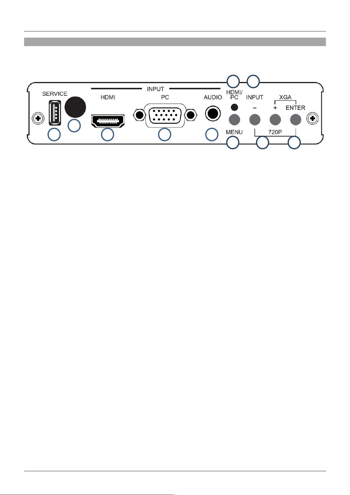
Overview
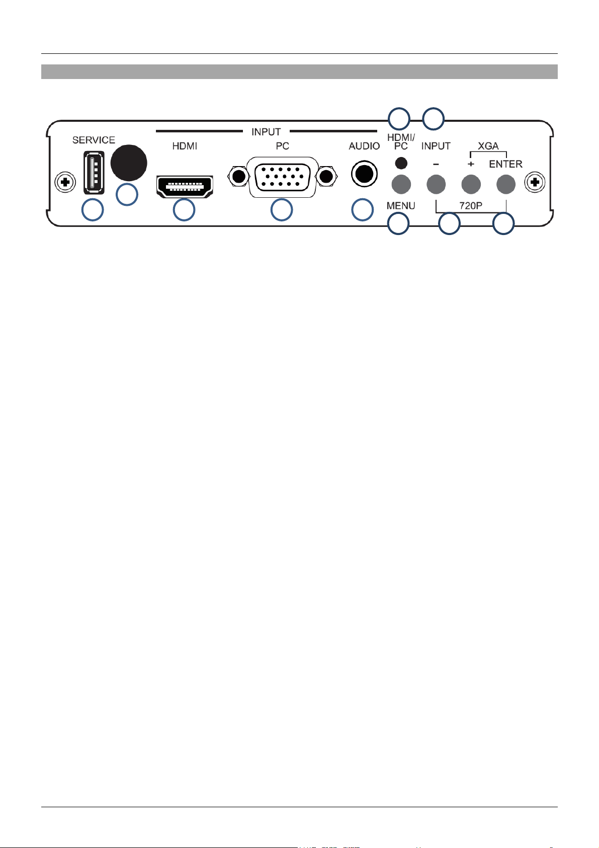
Front Panel
1. Service
This port is reserved for Firmware updates only.
2. IR
Receives the IR commands of the supplied IR Remote.
3. HDMI In
Connect to HDMI source equipment such as a PC or Blu-ray player.
4. VGA In
Connect to VGA source equipment such as a PC.
5. Audio In
Connect to audio equipment using a 3.5mm to 3.5mm or 3.5mm to Phono cable.
6. Menu
Press this button to enter the Transmitters On Screen Display (OSD).
7. Input
Press this button to quickly Switch between VGA and HDMI inputs.
8. HDMI/PC LED
Illuminates RED when HDMI input is active and Green when PC/VGA input is active.
9. -/+
When in the OSD menu use these buttons to navigate up and down.
10. Enter
When in the OSD menu press this button to make a selection. Press this button and – together to
instantly switch the output resolution to 720p@60. Press this button and + together to instantly
switch the output resolution to XGA 1024/768.
Page 5
User Manual English
1 2 3 4 5 6 7
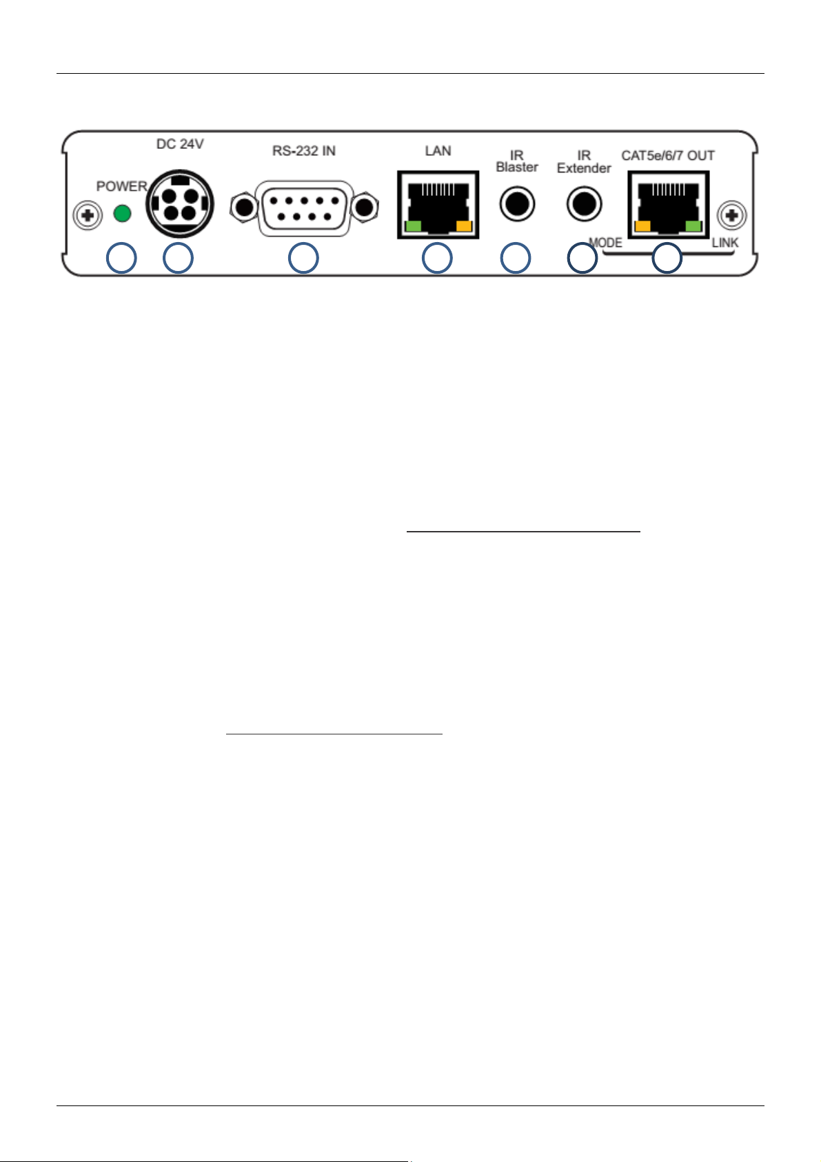
Back Panel
1. Power LED
Illuminates when the Transmitter is connected to the power supply.
2. DC 24V
Connect the power supply to this port. If using a 24V PoH (Power over HDBaseT) compatible
receiver, such as LINDY No. 38218, the receiver will not require a power supply.
3. RS-232 IN
Connect to a PC or Laptop with a 9 Way D cable for the transmission of RS-232 commands.
4. LAN
Connect to an internet or network connection – never connect to an HDBaseT port.
5. IR Blaster
Connect the supplied IR Blaster Cable for IR signal transmission. Place the IR Blaster in direct lineof-sight of the equipment to be controlled.
6. IR Extender
Connect the supplied IR Extender cable for IR signal reception. Ensure that remote being used is
within the direct line-of-sight of the IR Extender.
7. CAT5e/6/7 OUT
Connect to the CAT5e/6/7 IN port on the Receiver unit with a single CAT5e/6/7 cable for transmission
of all data signals – never connect to a network port. The yellow LED will illuminate to represent the
link from Receiver is stable, if it blinks irregularly it represents a link error or when not illuminated it
means no link with the Receiver. The green LED will illuminate to represent the HDMI signal contains
HDCP.
Page 6
User Manual English
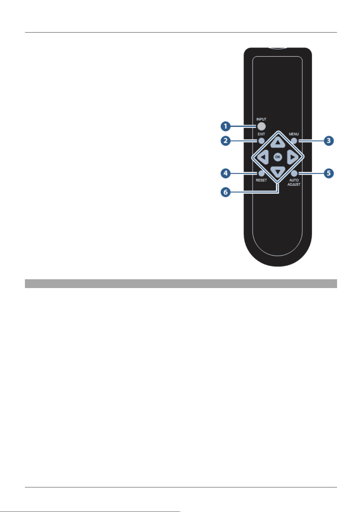
Remote Control
1. Input
Press this button to instantly switch between HDMI or VGA
inputs
2. Exit
Press this button to exit the menu or escape from the
current menu selection from within the OSD
3. Menu
Press this button to enter the OSD menu.
4. Reset
Press this button to set the Transmitter back to the factory
default setting.
5. Auto Adjust
Press this button to optimise/centre the positioning of the
picture on the screen.
6. Enter & ▲▼◄►
Press Enter to confirm a selection in the OSD, use the
arrow buttons to navigate the OSD.
Installation
Important! Before starting the installation, please ensure that all devices are powered off.
1. Connect your HDMI, VGA & Audio source equipment to the Transmitter using HDMI, VGA and
3.5mm audio cables.
2. Connect one end of the Cat.5e (max. length 80m) or Cat.6/7 cable (max. length 100m) to the
CAT.5e/6/7 Out (HDBaseT) port on the Transmitter and the other end to the CAT.5e/6/7 In
(HDBaseT) port of the HDBaseT Receiver (not included). Solid core installation cable is
recommended.
3. Use a HDMI cable to connect your HDMI display device to the HDMI output port on the HDBaseT
Receiver.
4. Plug the DC power supply into the Transmitter and switch on. If using a non 24V PoH equipped
HDBaseT Receiver please also connect the power supply for the Receiver and switch on.
5. Power on your source equipment and display then switch the Input you want to use to complete the
installation.
In addition to the basic installation steps outlined above the Transmitter can also provide the following
additional/optional functionality when used with a Receiver capable of the same features, such as LINDY
No. 38218:
10/100 Ethernet
The Transmitter and Receiver units both feature a single RJ45 port for the connection of network
equipment such as a Router, Network Switch, IP Camera, Wireless Access Point or Smart TV.
Page 7
User Manual English
HDMI & VGA Transmitter
PIN
Assignment
Baud Rate
9600bps
1
NC
Data Bit 8 2
TxD/RxD
Parity
None
3
RxD/TxD
Flow Control
None
4
NC
Stop Bit
1
5
GND
6
NC
7
NC
8
NC
9
NC
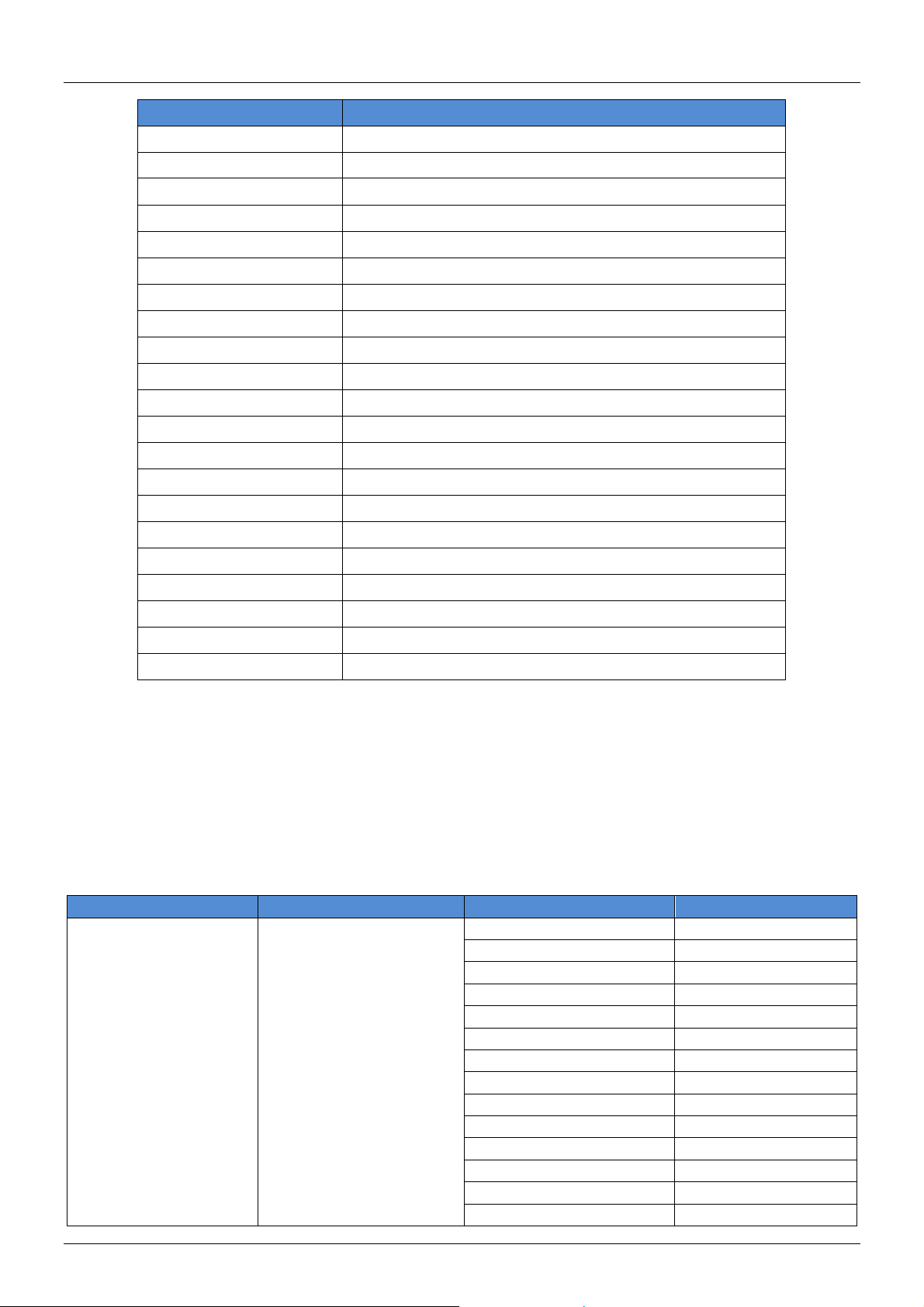
Command
Description
S SOURCE 1 – 2
1 = PC, 2 = HDMI
R SOURCE
Reports the numeric value of SOURCE setting as above
S OUTPUT 0 – 25
0=Native
1=640×480
2=800×600
3=1024×768
5=1360×768
6=1280×720
7=1280×800
8=1280×1024
9=1440×900
10=1400×1050
11=1680×1050
12=1600×1200
13=1920×1080
16=1920×1200
17=480p
18=720p@60
19=1080p@60
20=1080i@60
22=576p
23=720p@50
24=1080p@50
25=1080i@50
R OUTPUT
Reports the numeric value of OUTPUT setting as above
S SIZE 0 – 6
0=OVERSCAN
1=FULL
2=BEST FIT
3=PAN SCAN
4=LETTER BOX
5=UNDER 2
6=UNDER 1
R SIZE
Reports the numeric value of SIZE setting as above
S CONTRAST 0 – 60
Set the numeric value for CONTRAST from 0 – 60
RS-232 Serial
The Transmitter and Receiver both feature a 9 Way Serial connection for the extension of control
signals.
Infrared Control
The Transmitter and Receiver units both feature an IR In and Out port, with a pair of IR extension cables
provided. The extension cables allow an IR remote control to be used from the Transmitter to the
Receiver or vice versa.
RS-232 & On Screen Display
RS-232
Commands will be not executed unless followed with a carriage return (0x0D) and LF (Line Feed)
Commands are not case sensitive.
Resolutions 1 – 16 are RGB encoded, 17 – 25 are YUV encoded
Bold values are the default setting.
Page 8
User Manual English
Command
Description
R CONTRAST
Reports the numeric value of CONTRAST setting as above
S BRIGHTNESS 0 – 60
Set the numeric value for BRIGHTNESS from 0 – 60
R BRIGHTNESS
Reports the numeric value of BRIGHTNESS setting as above
S HUE 0 – 60
Set the numeric value for HUE from 0 – 60
R HUE
Reports the numeric value of HUE setting as above
S SATURATION 0 – 60
Set the numeric value for SATURATION from 0 – 60
R SATURATION
Reports the numeric value of SATURATION setting as above
S SHARPNESS 0 – 30
Set the numeric value for SHARPNESS from 0 – 30
R SHARPNESS
Reports the numeric value of SHARPNESS setting as above
S NR 0 – 3
0=OFF, 1=LOW, 2=MIDDLE, 3=HIGH
R NR
Reports the numeric value of NOISE REDUCTION setting as above
S AUDIO DELAY 0 – 3
0=OFF, 1=40ms, 2=110ms, 3=150ms
R AUDIO DELAY
Reports the numeric value of AUDIO DELAY setting as above
S AUDIO MUTE 0/1
0=ON, 1=OFF
R AUDIO MUTE
Reports the numeric value of AUDIO MUTE setting as above
S KEY LOCK 0/1
0=ENABLE, 1=DISABLE
R KEY LOCK
Reports the numeric value of KEY LOCK setting as above
S AUTOSCAN 0/1
0=DISABLE, 1=ENABLE
R AUTOSCAN
Reports the numeric value of AUTOSCAN setting as above
FW
Checks the current firmware version
S RESET 1
Resets the Transmitter to default values
1st Layer
2nd Layer
3rd Layer
4th Layer
DISPLAY
OUTPUT
Native
640X480 60
800x600 60
1024x768 60
1360x768 60
1280x720 60
1280x800 60
1280x1024 60
1440x900 60
1400x1050 60
1680x1050 60
1600x1200 60
1920x1080 60
1920x1200 60
OSD – On Screen Display
Enter the OSD by pressing the Menu button on either the Transmitter or the IR remote control.
Bold values are the default setting.
Page 9

User Manual English
1st Layer
2nd Layer
3rd Layer
4th Layer
DISPLAY (CONTINUED)
OUTPUT (CONTINUED)
720X480P 60
1280X720P 60
1920X1080I 60
1920X1080P 60
720X576P 50
1280X720P 50
1920X1080i 50
1920X1080P 50
Size
OVER SCAN
FULL
ASPECT RATIO
PAN SCAN
LETTER BOX
UNDER 2
UNDER 1
Mode Info
INFO
ON
OFF
PC (PC mode only)
AUTO SETUP
NO
YES
H_POSITION
0 – 60 (30)
V_POSITION
0 – 60 (30)
PHASE
CLOCK
WXGA/XGA
XGA
WXGA
COLOUR
COLOUR
RESET
NO
YES
R
G B R OFFSET
G OFFSET
B OFFSET
CONTRAST
0 – 60
BRIGHTNESS
0 – 60
HUE
0 – 60
SATURATION
0 – 60
SHARPNESS
0 – 30
NR
OFF
LOW
MIDDLE
HIGH
AUDIO
VOLUME
0 - 100
DELAY
OFF
40mS
110mS
150mS
SOUND
ON MUTE
Page 10
User Manual English
1st Layer
2nd Layer
3rd Layer
4th Layer
SETUP
FACTORY RESET
NO YES
KEY LOCK
OFF
ON
AUTO SCAN
OFF
ON
INFORMATION
INPUT
OUTPUT
REVISION
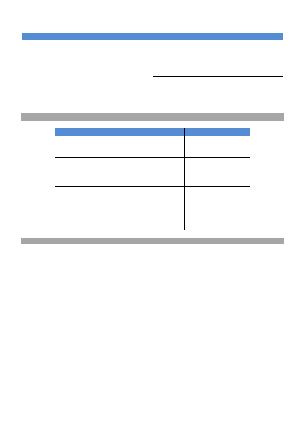
Input Resolution
HDMI
PC
VGA@60/72/75Hz
-
-
SVGA@56/60/72/75Hz
XGA@60/70/75Hz
SXGA@60/75Hz
UXGA@60Hz
1280x800@60Hz
1680x1050RB@60Hz
1920x1080@60Hz
480/576i
-
480/576p
-
720p@50/60Hz
-
1080i@50/60Hz
-
1080p@50/60Hz
-
Supported Input Resolutions
Troubleshooting
Check that the DC plug and jack used by the external power supply(ies) are firmly connected and
that the power LED is illuminated on both the Transmitter and Receiver.
Check that the Cat.5e/6/7 cable is plugged in correctly and that the Yellow Link Status LED on both
the CAT5e/6/7 In and Out ports are lit.
Power off all the devices, then power on in this order: first, the transmitter unit, then the display and
finally the source.
For several HDMI devices it may be helpful to unplug and replug their HDMI connection to re-initiate
the HDMI handshake and recognition.
Reduce the length of Cat.5e/6/7 or HDMI cable used, or use a higher quality cable.
Page 11

Benutzerhandbuch Deutsch
Einführung
Vielen Dank für den Kauf des LINDY C6 HDMI & VGA Switching Extender Transmitter. Dieser
Transmitter ermöglicht es Ihnen, mittels HDBaseT
Audiosignalen, Ethernet, RS-232 und IR-Signale über eine Distanz von bis zu 100m an einen HDBaseT
Receiver oder an Monitore sowie Projektoren mit integrierter HDBaseT Technology zu übertragen. Das
Umschalten zwischen HDMI und VGA ist durch einen Schalter, eine Fernbedienung oder auch durch
RS-232 Befehle sehr einfach und schnell zu erreichen – perfekt für die Integration in Meeting-Räumen,
Klassenräume oder in Schaltzentralen.
Für zusätzlichen Komfort und eine unauffällige Installation des Receivers unterstützt der Transmitter 24V
PoH (Power over HDBaseT), was die Nutzung mit nur einem Netzteil seitens des Transmitters
ermöglicht. Für die optimale Nutzung und um höhere Distanzen zu erreichen, empfehlen wir die Nutzung
von Installationskabeln mit starren Adern.
Lieferumfang
TM
Technology, HDMI oder VGA mit analogen
C6 HDMI & VGA Switching Extender Transmitter
24V Netzteil
C13 Stromkabel
IR Extender-Kabel (2x 1.4m)
IR Fernbedienung
Dieses Handbuch
Eigenschaften
Überträgt unkomprimierte HDMI und VGA-Signale über Distanzen von bis zu 100m mittels HDBaseT
Technology
Geeignet für die Nutzung mit HDBaseT fähigen Monitoren, Projektoren oder Receivern
Es wird nur ein Kabel benötigt um HDMI, VGA, RS-232, IR, Ethernet oder Audiosignale zu
übertragen
Integrierte 24V PoH Funktion (Power over HDBaseT) – kompatibel mit HDBaseT Receivern
Konzipiert für Hörsäle, Klassenräume, Verkaufsräume, professionelle HDTV Installationen oder
Multimedia- und Schaltzentralsysteme
Spezifikationen
Die Eingangssignale (HDMI oder VGA) können frei gewählt und bis zu 100m übertragen werden
Die Steuerung erfolgt durch eine Fernbedienung, OSD oder RS232
Unterstützt HDMI 1.4, HDCP, VGA, 10/100 Ethernet, RS-232 & IR
Die Verbindung erfolgt durch ein CAT5e Kabel (bis zu 80m) oder ein CAT6/7 Kabel (bis zu 100m)
Power-over-HDBaseT (24V PoH)
HDTV Auflösungen: 1080p24/30/50/60, 1080i, 720p, 576p & 480p
PC Auflösungen: ab 640x480 bis 1920x1200 RB
Integrierte Scaling-Funktion, ab 480-1080p, inklusive Over/Under/Pan/Full Scan
Unterstützt Deep Colour (30/36 Bit Farbtiefe)
Audio-Formate: LPCM, DTS Digital, DTS HD, Dolby Digital & Dolby True HD
Ermöglicht das Bedienen von IR Geräten (33-50kHz)
Farbtiefe, Sättigung und Bildschärfe einstellbar
Anschlüsse: HDMI In, VGA In, 3.5mm Stereo Audio In, RJ45 HDBaseT Out, 1 x Ethernet RJ45
10/100, DC in, 2 x 3.5mm IR (1 x Tx, 1 x Rx) & 9 Way Serial
Bi-direktionale IR-Unterstützung bei Nutzung eines kompatiblen Receivers
Abmessungen: 145 (W) x 202 (D) x 30 (H)mm
Gewicht: 0.608 kg
Page 12
Benutzerhandbuch Deutsch
1 2 3 4 5
6
8
7
9
10
Übersicht Anschlüsse
Vorderansicht
1. Service
Dieser Port ist für Firmware-Updates reserviert.
2. IR
Empfängt die IR-Befehle der im Lieferumfang enthaltenen Fernbedienung.
3. HDMI In
Verbindung zu HDMI-Quellen wie z.B. PCs oder Blu-ray Playern.
4. VGA In
Verbindung zu VGA-Quellen wie z.B. einem PC.
5. Audio In
Verbindung zu Audio-Zubehör mit einem 3.5mm auf 3.5mm oder einem 3.5mm auf RCA Kabel.
6. Menu
Betätigen Sie diesen Schalter um in das „On Screen“-Menü des Transmitters zu gelangen (OSD).
7. Input
Betätigen Sie diesen Schalter um die Eingangsquelle (HDMI oder VGA) zu wählen.
8. HDMI/PC LED
Leuchtet rot bei aktivem HDMI-Eingang und grün bei aktivem VGA-Eingang
9. -/+
Nutzen Sie diese beiden Schalter für die Navigation im “On-Screen”-Menü.
10. Enter
Nutzen Sie diesen Schalter um im “On-Screen”-Menü eine Auswahl zu treffen. Beim gleichzeitigen
Betätigen des „-„ Schalters wird die Ausgangsauflösung auf 720p60 gestellt. Beim gleichzeitigen
Betätigen des „+“ Schalters wird die Ausgangsauflösung auf XGA 1024/768 gestellt.
Page 13

Benutzerhandbuch Deutsch
1 2 3 4 5 6 7
Rückansicht
1. Power LED
Leuchtet wenn der Transmitter mit der Stromversorgung verbunden ist.
2. DC 24V
Verbinden Sie das Netzteil mit diesem Anschluss. Falls Sie einen 24V PoH (Power over HDBaseT)
kompatiblen Receiver nutzen (wie z.B. der LINDY Receiver mit der Artikelnummer 38218), benötigt
dieser keine zusätzliche Stromversorgung.
3. RS-232 IN
Verbindung zu PCs oder Notebook über ein serielles Kabel. Dient zur Übertragung von RS-232
Befehlen.
4. LAN
Verbindung zum Internet oder einer Netzwerkverbindung – Verbinden Sie diesen Anschluss niemals
mit einem HDBaseT Anschluss
5. IR Blaster
Verbindung für das im Lieferumfang enthaltene IR-Sendekabel. Stellen Sie sicher, dass sich das IRSendekabel in Sichtweite des zu bedienenden Geräts befindet.
6. IR Extender
Verbindung für das im Lieferumfang enthaltene IR-Empfängerkabel. Stellen Sie sicher, dass sich
das IR-Empfängerkabel in Sichtweite des IR-Extenders befindet.
7. CAT5e/6/7 OUT
Verbindung für das CAT5e/6/7 Kabel um alle Signale zu übertragen. Verbinden Sie diesen Anschluss
niemals mit einem Netzwerkanschluss. Wenn die Verbindung mit dem Receiver besteht, wird die
gelbe LED beginnen zu leuchten. Blinkt die LED, besteht ein Problem mit der Verbindung zum
Receiver. Wenn die grüne LED leuchtet, enthält das HDMI-Signal HDCP-Daten.
Page 14

Benutzerhandbuch Deutsch
Fernbedienung
1. Input
Betätigen Sie diesen Schalter um zwischen dem HDMI und
VGA-Eingang zu wechseln
2. Exit
Betätigen Sie diesen Schalter um das Menü oder ein
Untermenü des OSD-Menüs zu verlassen
3. Menu
Betätigen Sie diesen Schalter um das OSD-Menü zu öffnen
4. Reset
Betätigen Sie diesen Schalter um den Transmitter auf
Werkseinstellung zurück zu setzen
5. Auto Adjust
Betätigen Sie diese Schalter um die Position des Bildes auf
dem Monitor zu optimieren
6. Enter & ▲▼◄►
Betätigen Sie diesen Schalter um eine Auswahl im OSDMenü zu bestätigen – nutzen Sie die Pfeiltasten um im
OSD-Menü zu navigieren
Installation
WICHTIG! Stellen Sie sicher, dass alle Geräte vor der Installation abgeschalten sind.
1. Verbinden Sie Ihre HDMI, VGA & Audio Geräte mit dem Transmitter. Nutzen Sie hierfür geeignete
HDMI, VGA und 3.5mm Audiokabel.
2. Verbinden Sie das eine Ende des Cat.5e (max. Länge 80m) oder das Cat.6/7 Kabel (max. Länge
100m) mit dem HDBaseT Ausgangsport des Transmitters und das andere Ende mit dem HDBaseT
Eingangsport des Receivers (nicht im Lieferumfang enthalten). Wir empfehlen die Nutzung von
Installationskabeln mit starren Adern.
3. Nutzen sie ein geeignetes HDMI-Kabel und verbinden Sie den Monitor mit dem Ausgangsport des
HDBaseT-Receivers.
4. Verbinden Sie das Netzteil mit dem Transmitter und schalten Sie diesen ein. Falls Sie keinen 24V
PoH fähigen Receiver nutzen, verbinden Sie auch diesen mit dem Netzteil und schalten Sie den
Receiver im Anschluss ein.
5. Schalten Sie ihre Quellgeräte und Ihren Monitor oder Projektor ein und wählen Sie die gewünschte
Quelle um die Installation zu beenden.
Page 15

Benutzerhandbuch Deutsch
HDMI & VGA Transmitter
PIN
Assignment
Baud Rate
9600bps
1
NC
Data Bit 8 2
TxD/RxD
Parity
None
3
RxD/TxD
Flow Control
None
4
NC
Stop Bit
1
5
GND
6
NC
7
NC
8
NC
9
NC
Command
Description
S SOURCE 1 – 2
1 = PC, 2 = HDMI
R SOURCE
Reports the numeric value of SOURCE setting as above
Falls Sie einen Receiver mit den passenden Funktionen (wie z.B. den Receiver mit der LINDY ArtikelNr.
38218) nutzen, sind folgende Funktionen ebenfalls verfügbar:
10/100 Ethernet
Sowohl der Transmitter als auch der Receiver besitzt einen RJ45 Anschluss. Hiermit lassen sich
Netzwerkgeräte wie Router, Netzwerk-Switche, IP-Kameras, Kabellose Access Points und auch Smart
TVs verbinden.
Serielle RS-232 Schnittstelle
Sowohl der Transmitter als auch der Receiver besitzt einen RS-232 Anschluss um serielle Befehle zu
übertragen.
Infrarot
Sowohl der Transmitter als auch der Receiver besitzt einen IR Ein- und Ausgang (IR Kabel sind im
Lieferumfang enthalten). Dies ermöglicht die Übertragung von IR Signalen vom Transmitter zum
Receiver oder umgekehrt.
RS-232 & On Screen Display
RS-232
Befehle werden nicht ausgeführt bevor ein Zeilenumbruch (0x0D) oder ein Zeilenvorschub (Line
Feed) erfolgt
Befehle sind nicht abhängig von Groß- und Kleinschreibung.
Die Auflösungen 1-16 sind RGB verschlüsselt, 17-25 YUV verschlüsselt.
Die fett gedruckten Werte sind die Standardeinstellungen.
Page 16

Benutzerhandbuch Deutsch
Command
Description
S OUTPUT 0 – 25
0=Native
1=640×480
2=800×600
3=1024×768
5=1360×768
6=1280×720
7=1280×800
8=1280×1024
9=1440×900
10=1400×1050
11=1680×1050
12=1600×1200
13=1920×1080
16=1920×1200
17=480p
18=720p@60
19=1080p@60
20=1080i@60
22=576p
23=720p@50
24=1080p@50
25=1080i@50
R OUTPUT
Reports the numeric value of OUTPUT setting as above
S SIZE 0 – 6
0=OVERSCAN
1=FULL
2=BEST FIT
3=PAN SCAN
4=LETTER BOX
5=UNDER 2
6=UNDER 1
R SIZE
Reports the numeric value of SIZE setting as above
S CONTRAST 0 – 60
Set the numeric value for CONTRAST from 0 – 60
R CONTRAST
Reports the numeric value of CONTRAST setting as above
S BRIGHTNESS 0 – 60
Set the numeric value for BRIGHTNESS from 0 – 60
R BRIGHTNESS
Reports the numeric value of BRIGHTNESS setting as above
S HUE 0 – 60
Set the numeric value for HUE from 0 – 60
R HUE
Reports the numeric value of HUE setting as above
S SATURATION 0 – 60
Set the numeric value for SATURATION from 0 – 60
R SATURATION
Reports the numeric value of SATURATION setting as above
S SHARPNESS 0 – 30
Set the numeric value for SHARPNESS from 0 – 30
R SHARPNESS
Reports the numeric value of SHARPNESS setting as above
S NR 0 – 3
0=OFF, 1=LOW, 2=MIDDLE, 3=HIGH
R NR
Reports the numeric value of NOISE REDUCTION setting as above
S AUDIO DELAY 0 – 3
0=OFF, 1=40ms, 2=110ms, 3=150ms
R AUDIO DELAY
Reports the numeric value of AUDIO DELAY setting as above
S AUDIO MUTE 0/1
0=ON, 1=OFF
R AUDIO MUTE
Reports the numeric value of AUDIO MUTE setting as above
S KEY LOCK 0/1
0=ENABLE, 1=DISABLE
R KEY LOCK
Reports the numeric value of KEY LOCK setting as above
S AUTOSCAN 0/1
0=DISABLE, 1=ENABLE
R AUTOSCAN
Reports the numeric value of AUTOSCAN setting as above
FW
Checks the current firmware version
S RESET 1
Resets the Transmitter to default values
Page 17

Benutzerhandbuch Deutsch
1st Layer
2nd Layer
3rd Layer
4th Layer
DISPLAY
OUTPUT
Native
640X480 60
800x600 60
1024x768 60
1360x768 60
1280x720 60
1280x800 60
1280x1024 60
1440x900 60
1400x1050 60
1680x1050 60
1600x1200 60
1920x1080 60
1920x1200 60
DISPLAY (CONTINUED)
OUTPUT (CONTINUED)
720X480P 60
1280X720P 60
1920X1080I 60
1920X1080P 60
720X576P 50
1280X720P 50
1920X1080i 50
1920X1080P 50
Size
OVER SCAN
FULL
ASPECT RATIO
PAN SCAN
LETTER BOX
UNDER 2
UNDER 1
Mode Info
INFO
ON
OFF
PC (PC mode only)
AUTO SETUP
NO
YES
H_POSITION
0 – 60 (30)
V_POSITION
0 – 60 (30)
PHASE
CLOCK
WXGA/XGA
XGA
WXGA
COLOUR
COLOUR
RESET
NO
YES
R
OSD – On Screen Display
Öffnen Sie das OSD-Menü indem Sie den Menüschalter auf dem Transmitter oder der Fernbedienung
betätigen
Die fett gedruckten Werte sind die Standardeinstellungen
Page 18

Benutzerhandbuch Deutsch
1st Layer
2nd Layer
3rd Layer
4th Layer
G B R OFFSET
G OFFSET
B OFFSET
CONTRAST
0 – 60
BRIGHTNESS
0 – 60
HUE
0 – 60
SATURATION
0 – 60
SHARPNESS
0 – 30
NR
OFF
LOW
MIDDLE
HIGH
AUDIO
VOLUME
0 - 100
DELAY
OFF
40mS
110mS
150mS
SOUND
ON
MUTE
SETUP
FACTORY RESET
NO YES
KEY LOCK
OFF
ON
AUTO SCAN
OFF
ON
INFORMATION
INPUT
OUTPUT
REVISION
Input Resolution
HDMI
PC
VGA@60/72/75Hz
-
-
SVGA@56/60/72/75Hz
XGA@60/70/75Hz
SXGA@60/75Hz
UXGA@60Hz
1280x800@60Hz
1680x1050RB@60Hz
1920x1080@60Hz
480/576i
-
480/576p
-
720p@50/60Hz
-
1080i@50/60Hz
-
1080p@50/60Hz
-
Supported Input Resolutions
Page 19

Benutzerhandbuch Deutsch
Troubleshooting
Überprüfen Sie ob der Stecker des Netzeils richtig angeschlossen ist und ob die Power-LED des
Transmitters und Receivers leuchtet.
Überprüfen Sie ob die Cat.5e/6/7 Kabel richtig angeschlossen sind und ob die gelbe Status-LED des
Eingangs- und Ausgangsports leuchtet.
Schalten Sie alle Geräte ab und in folgender Reihenfolge wieder ein: Transmitter -> Monitor oder
Projektor -> Quellgeräte.
Bei einigen Geräten kann es hilfreich sein die HDMI-Verbindung für kurze Zeit zu lösen und direkt im
Anschluss wiederherzustellen um einen erfolgreichen Handshake zu generieren.
Reduzieren Sie die Kabellänge der Cat.5e/6/7 Kabel oder nutzen Sie ein Kabel höherer Qualität.
Page 20

Manuel Utilisateur Français
Introduction
Merci d’avoir choisi le LINDY C6 HDMI & VGA Switching Extender Transmitter. Utilisant la technologie
HDBaseTTM, cet émetteur vous permet de transmettre des signaux HDMI ou VGA avec le son
analogique, Ethernet, RS-232, et infrarouge jusqu’à 100m en utilisant un seul câble RJ45 Cat.6/Cat.7 de
haute qualité vers un récepteur HDBaseT ou un affichage/projecteur avec technologie HDBaseT
intégrée. La commutation entre les entrées HDMI et VGA est rapide et simple à effectuer, par appuis sur
un bouton, à l’aide de la télécommande IR ou par commandes RS-232, ce produit est parfait pour une
intégration dans les salles de réunion, salles de cours ou dans les salles de contrôle.
Pour plus de commodité et pour permettre une installation discrète d’un récepteur, l’émetteur prend en
charge la fonction d’alimentation en 24V PoH (Power over HDBaseT) permettant l’utilisation d’une seule
alimentation avec l’émetteur pour alimenter les deux unités (émetteur et récepteur). Pour de meilleurs
résultats et plus spécialement pour les grandes longueurs, nous recommandons l’utilisation de câble
monobrin. Contenu de la livraison
Contenu de l’emballage
C6 HDMI & VGA Switching Extender
Transmitter
Alimentation 24V
Câble d’alimentation secteur C13
Câbles d’extension IR 1.4m x 2
Télécommande IR
Ce manuel
Caractéristiques
Transmet des signaux HDMI/VGA non compresses jusqu’à 100m en utilisant la technologie
HDBaseT
A utiliser avec des affichages, projecteurs et récepteurs équipés en HDBaseT
Utilise un seul câble pour transmettre les signaux HDMI, VGA, RS-232, IR, Ethernet et audio
Fonctionnalités Power over HDBaseT (24V PoH) intégrée pour une utilisation avec des récepteurs
HDBaseT compatibles
Conçu pour être utilisé dans des salles de conférence, salles de cours, showroom, installations
HDTV professionnelles, installations multimédia et salles de contrôle
Spécifications
Prend en charge les entrées HDMI & VGA et transmet l’entrée sélectionnée jusqu’à 100m
Contrôlé via télécommande IR, OSD ou RS232
Transmet les signaux HDMI 1.4, HDCP, VGA, 10/100 Ethernet, RS-232 & IR jusqu’à 100m via
technologie HDBaseT
Liaison via câble CAT5e (jusqu’à 80m) ou CAT6/7 (jusqu’à 100m)
Fonction Power-over-HDBaseT (24V PoH) pour une utilisation avec des récepteurs compatibles
Résolutions HDTV: 1080p24/30/50/60, 1080i, 720p, 576p & 480p
Résolutions PC: de 640x480 à 1920x1200 RB
Fonction de mise à l’échelle intégrée, de 480-1080p, avec Over/Under/Pan/Full Scan
Capacité Deep Colour: prend en charge les profondeurs de couleurs 30/36 bit
Formats audio: LPCM, DTS Digital, DTS HD, Dolby Digital & Dolby True HD
Contrôle des équipements IR (33-50kHz) via l’extender
Contrôle de la teinte, saturation et netteté
Ports: HDMI In, VGA In, jack audio stéréo 3,5mm In, RJ45 HDBaseT Out, 1 x Ethernet RJ45 10/100,
DC in, 2 x jack 3,5mm IR (1 x Tx, 1 x Rx) & D9 série
Prise en charge IR bidirectionnelle lorsque utilisé avec un récepteur compatible
Dimensions: 145 (L) x 202 (l) x 30 (H) mm
Poids: 0.608 kg
HDBaseT™ et le logo HDBaseT Alliance sont des marques de l’Alliance HDBaseT
Page 21

Manuel Utilisateur Français
1 2 3 4 5
6
8
7
9
10
Vue d’ensemble
Panneau avant
1. Service
Ce port est réservé aux mises à jour du Firmware.
2. IR
Reçoit les commandes IR de la télécommande IR fournie.
3. HDMI In
Se connecte la source HDMI, comme un PC ou un lecteur Blu-ray.
4. VGA In
Se connecte à la source VGA comme un PC.
5. Audio In
Se connecte à l’équipement audio avec un câble jack 3,5mm vers 3,5mm ou jack 3,5mm vers RCA.
6. Menu
Appuyez sur ce bouton pour afficher le menu On Screen Display (OSD) de l’émetteur.
7. Input
Appuyez sur ce bouton pour commuter rapidement entre les entrées VGA et HDMI.
8. HDMI/PC LED
En rouge lorsque l’entrée HDMI est active et verte lorsque l’entrée PC/VGA est active.
9. -/+
Utilisez ces boutons pour naviguer dans le menu OSD.
10. Enter
Dans le menu OSD, appuyez sur ce bouton pour valider une sélection. Pressez sur ce bouton et sur
‘’–‘’ en même temps pour commuter instantanément la résolution de sortie en 720p@60. Pressez
sur ce bouton et sur ‘’+’’ en même temps pour commuter instantanément la résolution en sortie en
XGA 1024/768.
Page 22

Manuel Utilisateur Français
1 2 3 4 5 6 7
Panneau arrière
1. Power LED
S’allume lorsque l’émetteur est alimenté.
2. DC 24V
Connectez l’alimentation à ce port. Si vous utilisez un récepteur compatible 24V PoH (Power over
HDBaseT), comme le N°Art LINDY 38218, le récepteur n’aura pas besoin d’être alimenté.
3. RS-232 IN
Connectez ici un PC ou Laptop avec un câble série D9 pour la transmission des commandes
RS-232.
4. LAN
Connectez ici une liaison internet ou réseau local – ne jamais connecter à un port HDBaseT.
5. IR Blaster
Connectez ici le câble émetteur IR fourni (IR Blaster Cable) pour la transmission des signaux IR.
Placez ce câble directement en face de l’équipement à contrôler.
6. IR Extender
Connectez ici le câble récepteur IR fourni (IR Extender Cable) pour la réception des signaux IR.
Assurez-vous que la télécommande pointe directement sur le récepteur IR.
7. CAT5e/6/7 OUT
Connectez un câble CAT5e/6/7 à ce port, relie-le ensuite au port CAT5e/6/7 IN du récepteur, pour la
transmission de tous les signaux de données – ne jamais connecter à un port réseau. La LED jaune
va s’allumer pour indiquer une liaison stable avec le récepteur, si la LED clignote de façon irrégulière
cela voudra dire qu’il y a une erreur sur la liaison, si le voyant reste éteint cela indiquera qu’aucune
liaison n’est établie avec le récepteur. La LED verte s’allume lorsque le signal HDMI contient un
signal HDCP.
Page 23

Manuel Utilisateur Français
Télécommande
1. Input
Appuyez sur ce bouton pour commuter entre les entrées
HDMI ou VGA
2. Exit
Appuyez sur ce bouton pour sortir du menu ou pour
accéder au menu précédent dans l’OSD
3. Menu
Appuyez sur ce bouton pour accéder au menu OSD.
4. Reset
Appuyez sur ce bouton pour revenir aux paramètres
d’usine.
5. Auto Adjust
Appuyez sur ce bouton pour optimiser/centrer la position de
l’image à l’écran.
6. Enter & ▲▼◄►
Appuyez sur Enter pour confirmer une sélection dans
l’OSD, utilisez les flèches pour naviguer dans l’OSD.
Installation
Important! Avant de débuter l’installation, assurez-vous que tous les appareils soient hors-tension.
1. Connectez vos équipements sources HDMI, VGA & Audio à l’émetteur en utilisant des câbles HDMI,
VGA et jack audio 3,5mm.
2. Connectez une extrémité du câble Cat.5e (longueur max. 80m) ou Cat.6/7 (longueur max. 100m) au
port CAT.5e/6/7 Out (HDBaseT) sur l’émetteur et l’autre extrémité au port CAT.5e/6/7 In (HDBaseT)
du récepteur HDBaseT (non fourni). Nous recommandons l’utilisation de câble monobrin.
3. Utilisez un câble HDMI pour connecter un affichage HDMI au port HDMI de sortie sur le récepteur
HDBaseT.
4. Branchez l’alimentation DC sur l’émetteur et mettez-le sous tension. Si le récepteur HDBaseT n’est
pas compatible 24V PoH, connectez également l’alimentation fournie avec le récepteur.
5. Mettez vos équipements source ainsi que l’affichage sous tension et commutez l’entrée que vous
désirez utiliser pour compléter l’installation.
En plus des étapes d’installation basiques ci-dessus, l’émetteur dispose également des fonctionnalités
additionnelles/optionnelles suivantes, lorsque utilisé avec un récepteur ayant les mêmes capacités,
comme le N°Art. LINDY 38218:
10/100 Ethernet
L’émetteur et le récepteur disposent tous deux d’un port RJ45 pour la connexion d’équipements réseau
comme un routeur, switch réseau, caméra IP, point d’accès sans fil (Wi-Fi) ou d’une Smart TV.
Page 24

Manuel Utilisateur Français
Emetteur HDMI & VGA
PIN
Affectation
Baud Rate
9600bps
1
NC
Data Bit 8 2
TxD/RxD
Parity
None
3
RxD/TxD
Flow Control
None
4
NC
Stop Bit
1
5
GND
6
NC
7
NC
8
NC
9
NC
Commande
Description
S SOURCE 1 – 2
1 = PC, 2 = HDMI
R SOURCE
Rapporte la valeur numérique du paramètre SOURCE ci-dessus
S OUTPUT 0 – 25
0=Native
1=640×480
2=800×600
3=1024×768
5=1360×768
6=1280×720
7=1280×800
8=1280×1024
9=1440×900
10=1400×1050
11=1680×1050
12=1600×1200
13=1920×1080
16=1920×1200
17=480p
18=720p@60
19=1080p@60
20=1080i@60
22=576p
23=720p@50
24=1080p@50
25=1080i@50
R OUTPUT
Rapporte la valeur numérique du paramètre OUTPUT ci-dessus
S SIZE 0 – 6
0=OVERSCAN
1=FULL
2=BEST FIT
3=PAN SCAN
4=LETTER BOX
5=UNDER 2
6=UNDER 1
R SIZE
Rapporte la valeur numérique du paramètre SIZE ci-dessus
RS-232 série
L’émetteur et le récepteur disposent tous deux d’un port série D9 pour la transmission des signaux de
contrôle RS232.
Contrôle infrarouge
L’émetteur et le récepteur disposent tous deux de ports IR In et Out, avec deux câbles d’extension IR
fournies. Ces câbles permettent à une télécommande infrarouge d’être utilisée côté émetteur ou côté
récepteur.
RS-232 & On Screen Display
RS-232
Les commandes ne seront pas exécutées si elles ne sont pas suivies par un retour chariot (carriage
return - 0x0D) et LF (Line Feed)
Les commandes ne sont pas sensibles à la casse.
Résolutions 1 – 16 sont codées en RGB, 17 – 25 sont codés en YUV
Les valeurs en gras sont celles qui sont actives par défaut.
Page 25

Manuel Utilisateur Français
Commande
Description
S CONTRAST 0 – 60
Défini la valeur numérique de CONTRAST de 0 – 60
R CONTRAST
Rapporte la valeur du réglage de CONTRAST ci-dessus
S BRIGHTNESS 0 – 60
Défini la valeur numérique de BRIGHTNESS de 0 – 60
R BRIGHTNESS
Rapporte la valeur du réglage de BRIGHTNESS ci-dessus
S HUE 0 – 60
Défini la valeur numérique de HUE de 0 – 60
R HUE
Rapporte la valeur du réglage de HUE ci-dessus
S SATURATION 0 – 60
Défini la valeur numérique de SATURATION de 0 – 60
R SATURATION
Rapporte la valeur du réglage de SATURATION ci-dessus
S SHARPNESS 0 – 30
Défini la valeur numérique de SHARPNESS de 0 – 30
R SHARPNESS
Rapporte la valeur du réglage de SHARPNESS ci-dessus
S NR 0 – 3
0=OFF, 1=LOW, 2=MIDDLE, 3=HIGH
R NR
Rapporte la valeur du réglage de NOISE REDUCTION ci-dessus
S AUDIO DELAY 0 – 3
0=OFF, 1=40ms, 2=110ms, 3=150ms
R AUDIO DELAY
Rapporte la valeur du réglage de AUDIO DELAY ci-dessus
S AUDIO MUTE 0/1
0=ON, 1=OFF
R AUDIO MUTE
Rapporte la valeur du réglage de AUDIO MUTE ci-dessus
S KEY LOCK 0/1
0=ENABLE, 1=DISABLE (0=désactivé, 1=activé)
R KEY LOCK
Rapporte la valeur du réglage de KEY LOCK ci-dessus
S AUTOSCAN 0/1
0=DISABLE, 1=ENABLE (0=désactivé, 1=activé)
R AUTOSCAN
Rapporte la valeur du réglage de AUTOSCAN ci-dessus
FW
Permet de vérifier la version actuelle du Firmware
S RESET 1
Reset de l’émetteur aux valeurs par défaut
1st Layer
2nd Layer
3rd Layer
4th Layer
DISPLAY
OUTPUT
Native
640X480 60
800x600 60
1024x768 60
1360x768 60
1280x720 60
1280x800 60
1280x1024 60
1440x900 60
1400x1050 60
1680x1050 60
1600x1200 60
1920x1080 60
OSD – On Screen Display
Entrez dans l’OSD en appuyant sur le bouton Menu sur l’émetteur ou sur la télécommande IR.
Les valeurs en gras sont celles qui sont actives par défaut.
Page 26

Manuel Utilisateur Français
1st Layer
2nd Layer
3rd Layer
4th Layer
1920x1200 60
DISPLAY (suite)
OUTPUT (suite)
720X480P 60
1280X720P 60
1920X1080I 60
1920X1080P 60
720X576P 50
1280X720P 50
1920X1080i 50
1920X1080P 50
Size
OVER SCAN
FULL
ASPECT RATIO
PAN SCAN
LETTER BOX
UNDER 2
UNDER 1
Mode Info
INFO
ON
OFF
PC (PC mode only)
AUTO SETUP
NO
YES
H_POSITION
0 – 60 (30)
V_POSITION
0 – 60 (30)
PHASE
CLOCK
WXGA/XGA
XGA
WXGA
COLOUR
COLOUR
RESET
NO YES
R G B R OFFSET
G OFFSET
B OFFSET
CONTRAST
0 – 60
BRIGHTNESS
0 – 60
HUE
0 – 60
SATURATION
0 – 60
SHARPNESS
0 – 30
NR
OFF
LOW
MIDDLE
HIGH
AUDIO
VOLUME
0 - 100
DELAY
OFF
40mS
110mS
150mS
SOUND
ON
Page 27

Manuel Utilisateur Français
1st Layer
2nd Layer
3rd Layer
4th Layer
MUTE
SETUP
FACTORY RESET
NO YES
KEY LOCK
OFF
ON
AUTO SCAN
OFF
ON
INFORMATION
INPUT
OUTPUT
REVISION
Résolutions en entrée
HDMI
PC
VGA@60/72/75Hz
-
-
SVGA@56/60/72/75Hz
XGA@60/70/75Hz
SXGA@60/75Hz
UXGA@60Hz
1280x800@60Hz
1680x1050RB@60Hz
1920x1080@60Hz
480/576i
-
480/576p
-
720p@50/60Hz
-
1080i@50/60Hz
-
1080p@50/60Hz
-
Résolutions prises en charge en entrée
Dépannage
Vérifiez que les alimentations DC sont bien branchées et que les LED d’alimentation sont allumées
sur l’émetteur et le récepteur.
Vérifiez que le câble Cat.5e/6/7 est bien connecté et que les LED jaune d’état de la liaison sont bien
allumées sur les ports CAT5e/6/7 In et Out.
Mettez tous les appareils hors tension, puis mettez-les sous tension dans l’ordre suivant: en premier,
l’émetteur, puis l’affichage et finalement la source.
Pour certains appareils HDMI il peut être nécessaire de déconnecter et reconnecter leurs connexions
HDMI pour réinitialiser le handshake et la détection HDMI.
Réduisez la longueur des câbles Cat.5e/6/7 ou HDMI, ou utilisez des câbles de qualité supérieure.
Page 28

Manuale Italiano
Introduzione
Grazie per aver scelto il LINDY C6 HDMI & VGA Switching Extender Transmitter. Questo trasmettitore
invia tramite la tecnologia HDBaseTTM, segnali HDMI o VGA con Audio analogico, Ethernet, RS-232, e IR
fino a 100m collegando un ricevitore HDBaseT con un singolo cavo di rete di alta qualità Cat.6/Cat.7 RJ45
o un monitor/proiettore con funzione HDBaseT. La commutazione tra ingressi HDMI e VGA è facile e
veloce e può avvenire premendo il relativo tasto, con il telecomando IR o con comandi RS-232,
rendendolo la soluzione ideale per sale congressi, aule o centrali di controllo.
Per poter effettuare installazioni con praticità, il trasmettitore supporta 24V PoH (Power over HDBaseT)
consentendo di utilizzare un solo alimentatore per alimentare entrambe le unità. Per ottenere risultati
migliori in particolare su lunghe distanze, consigliamo l’uso di un cavo solid core/structured.
Contenuto della confezione
C6 HDMI & VGA Switching Extender Transmitter
Alimentatore 24V
Cavo alimentazione C13
Cavo IR Extender 1.4m x 2
Telecomando IR
Questo manuale
Caratteristiche
Estende segnali non compressi HDMI/VGA fino a 100m tramite la tecnologia HDBaseT
Adatto all’utilizzo con monitor, proiettori o ricevitori con funzione HDBaseT
Estensione di segnali HDMI, VGA, RS-232, IR, Ethernet e Audio
Funzione Power over HDBaseT (24V PoH) integrata per l’uso con ricevitori HDBaseT
Ideale per l’utilizzo in installazioni professionali HDTV e multimediali, scuole, showroom, ecc
Specifiche
Accetta segnali HDMI & VGA ed estende l’ingresso selezionato fino a 100m
Controllabile via telecomando, OSD o RS232
Estende segnali HDMI 1.4, HDCP, VGA, 10/100 Ethernet, RS-232 & IR fino a 100m tramite la
tecnologia HDBaseT
Connessione via cavo CAT5e (fino a 80m) o CAT6/7 (fino a 100m)
Funzione Power-over-HDBaseT (24V PoH) per l’uso on ricevitori compatibili
Risoluzioni HDTV: 1080p24/30/50/60, 1080i, 720p, 576p & 480p
Risoluzioni PC: da 640x480 a 1920x1200 RB
Funzione scaling, da 480-1080p, incluso Over/Under/Pan/Full Scan
Supporto Deep Colour 30/36 bit
Formati Audio: LPCM, DTS Digital, DTS HD, Dolby Digital & Dolby True HD
Supporta segnali IR (33-50kHz)
Tonalità, saturazione e nitidezza regolabili
Porte: HDMI In, VGA In, 3.5mm Stereo Audio In, RJ45 HDBaseT Out, 1 x Ethernet RJ45 10/100, DC
in, 2 x 3.5mm IR (1 x Tx, 1 x Rx) & 9 poli Seriale
Supporto IR bidirezionale se usato con un ricevitore compatibile
Dimensioni: 145 x 202 x 30mm
Peso: 0.608 kg
I loghi HDBaseT™ e HDBaseT Alliance sono marchi registrati di HDBaseT Alliance
Page 29

Manuale Italiano
1 2 3 4 5
6
8
7
9
10
Panoramica
Pannello frontale
1. Service
Porta riservata solo all’aggiornamento del Firmware.
2. IR
Riceve i comandi IR del telecomando incluso nella fornitura.
3. HDMI In
Connessione ad una sorgente HDMI.
4. VGA In
Connessione ad una sorgente VGA.
5. Audio In
Connessione to audio equipment using a 3.5mm to 3.5mm or 3.5mm to Phono cable.
6. Menu
Tasto per entrare nel menu On Screen Display (OSD).
7. Input
Tasto per commutare tra gli ingressi VGA e HDMI.
8. HDMI/PC LED
Si illumina di rosso quando l’ingresso HDMI è attivo e verde quando l’ingresso PC/VGA è attivo.
9. -/+
Tasti per scorrere nel menu OSD.
10. Enter
Testo per confermare una selezione nel menu OSD. Premete questo tasto insieme al tasto – per
modificare la risoluzione in uscita a 720p@60. Premete questo tasto insieme al tasto + per modificare
la risoluzione in uscita a XGA 1024/768.
Page 30

Manuale Italiano
1 2 3 4 5 6 7
Pannello posterior
1. Power LED
Si illumina quando il trasmettitore è alimentato.
2. DC 24V
Porta per collegare l’alimentatore. Se utilizzate un ricevitore compatibile PoH 24V (Power over
HDBaseT) come il LINDY Art. 38218, questo non necessita di un alimentatore aggiuntivo.
3. RS-232 IN
Connessione ad un PC con porta seriale 9 poli per la trasmissione di comandi via RS-232.
4. LAN
Connessione ad internet o ad una rete – non connettere mai un dispositivo HDBaseT.
5. IR Blaster
Connessione del cavo IR Blaster per la trasmissione di segnali IR. Posizionare il cavo in prossimità
del dispositivo che si intende controllare.
6. IR Extender
Connessione del cavo IR Extender per la ricezione di segnali IR. Posizionare il cavo in prossimità del
dispositivo che si intende controllare.
7. CAT5e/6/7 OUT
Porta per la connessione di un cavo CAT5e/6/7 per la trasmissione di tutti i segnali – non connetterla
mai ad una porta di rete. Il LED giallo si illuminerà una volta che il segnale inviato al ricevitore è
stabile, se lampeggia irregolarmente significa che c’è un errore nella connessione, se invece non si
illumina significa che non c’è connessione con il ricevitore. Il LED verde si illuminerà nel caso in cui il
segnale HDMI ha la codifica HDCP.
Page 31

Manuale Italiano
Telecomando
1. Input
Tasto per la commutazione tra gli ingressi HDMI e VGA
2. Exit
Tasto per uscire dal menu o da un sotto menu OSD
3. Menu
Tasto per entrare nel menu OSD.
4. Reset
Tasto per ripristinare il trasmettitore alle impostazioni di
default.
5. Auto Adjust
Tasto per ottimizzare/centrare il posizionamento
dell’immagine sul monitor.
6. Enter & ▲▼◄►
Tasto OK per confermare la selezione nel menu OSD,
le frecce per navigare nel menu OSD.
Installazione
Importante! Prima di iniziare l’installazione assicuratevi che tutti i dispositivi siano spenti.
1. Collegate la vostra sorgente HDMI, VGA & Audio al trasmettitore con dei cavi HDMI, VGA e audio
3.5mms.
2. Collegate un capo del cavo di rete Cat.5e (lunghezza massima 80m) o Cat.6/7 (lunghezza massima
100m) all’uscita CAT.5e/6/7 (HDBaseT) sul trasmettitore e l’altro capo alla porta (HDBaseT) del
ricevitore (non incluso). Consigliamo un cavo solid core.
3. Utilizzate un cavo HDMI per connettere il monitor HDMI all’uscita HDMI del ricevitore HDBaseT.
4. Collegate l’alimentatore al trasmettitore ed accendetelo. Se utilizzate un ricevitore che non è 24V PoH
HDBaseT collegate anche l’alimentatore del ricevitore ed accendetelo.
5. Alimentate anche la sorgente e il monitor quindi commutate sull’ingresso desiderato per completare
l’installazione.
In aggiunta ai passaggi indicate qui sopra, il trasmettitore può anche avere le seguenti funzionalità
addizionali/opzionali quando è utilizzato con un ricevitore con le stesse caratteristiche come il LINDY Art.
38218:
10/100 Ethernet
Trasmettitore e ricevitore hanno entrambi una porta RJ45 per la connessione ad una rete come un
Router, Switch, IP Camera, Access Point Wireless o Smart TV.
Page 32

Manuale Italiano
Trasmettitore HDMI & VGA
PIN
Assignment
Baud Rate
9600bps 1 NC
Data Bit 8 2
TxD/RxD
Parity
None
3
RxD/TxD
Flow Control
None
4
NC
Stop Bit
1
5
GND
6
NC
7
NC
8
NC
9
NC
Comandi
Descrizione
S SOURCE 1 – 2
1 = PC, 2 = HDMI
R SOURCE
Restituisce il valore numerico SOURCE
S OUTPUT 0 – 25
0=Native
1=640×480
2=800×600
3=1024×768
5=1360×768
6=1280×720
7=1280×800
8=1280×1024
9=1440×900
10=1400×1050
11=1680×1050
12=1600×1200
13=1920×1080
16=1920×1200
17=480p
18=720p@60
19=1080p@60
20=1080i@60
22=576p
23=720p@50
24=1080p@50
25=1080i@50
R OUTPUT
Restituisce il valore numerico OUTPUT
S SIZE 0 – 6
0=OVERSCAN
1=FULL
2=BEST FIT
3=PAN SCAN
4=LETTER BOX
5=UNDER 2
6=UNDER 1
R SIZE
Restituisce il valore numerico SIZE
S CONTRAST 0 – 60
Imposta il valore CONTRAST da 0 a 60
R CONTRAST
Restituisce il valore numerico CONTRAST
Seriale RS-232
Trasmettitore e ricevitore hanno entrambi una porta seriale 9 pin per l’estensione di segnali seriali.
Controllo infrarossi
Trasmettitore e ricevitore hanno entrambi porte IR In e Out con i relativi cavi IR inclusi. Questi cavi
consentono di controllare un telecomando IR dal trasmettitore al ricevitore o vice versa.
RS-232 & On Screen Display
RS-232
I comandi non vengono eseguiti se non sono seguiti da CR (0x0D) e LF (Line Feed)
I comandi non tengono conto del carattere maiuscolo o minuscolo.
Le risoluzioni 1 – 16 sono codifiche RGB, 17 – 25 sono codifiche YUV
I valori in grassetto sono quelli predefiniti
Page 33

Manuale Italiano
Comandi
Descrizione
S BRIGHTNESS 0 – 60
Imposta il valore BRIGHTNESS da 0 a 60
R BRIGHTNESS
Restituisce il valore numerico BRIGHTNESS
S HUE 0 – 60
Imposta il valore HUE da 0 a 60
R HUE
Restituisce il valore numerico HUE
S SATURATION 0 – 60
Imposta il valore SATURATION da 0 a 60
R SATURATION
Restituisce il valore numerico SATURATION
S SHARPNESS 0 – 30
Imposta il valore SHARPNESS da 0 a 30
R SHARPNESS
Restituisce il valore numerico SHARPNESS setting as above
S NR 0 – 3
0=OFF, 1=LOW, 2=MIDDLE, 3=HIGH
R NR
Restituisce il valore numerico NOISE REDUCTION setting as
S AUDIO DELAY 0 – 3
0=OFF, 1=40ms, 2=110ms, 3=150ms
R AUDIO DELAY
Restituisce il valore numerico AUDIO DELAY setting as above
S AUDIO MUTE 0/1
0=ON, 1=OFF
R AUDIO MUTE
Restituisce il valore numerico AUDIO MUTE setting as above
S KEY LOCK 0/1
0=ENABLE, 1=DISABLE
R KEY LOCK
Restituisce il valore numerico KEY LOCK setting as above
S AUTOSCAN 0/1
0=DISABLE, 1=ENABLE
R AUTOSCAN
Restituisce il valore numerico AUTOSCAN setting as above
FW
Controlla la versione del Firware corrente
S RESET 1
Reimposta tutti i valori alle impostazioni di fabbrica
1st Livello
2nd Livello
3rd Livello
4th Livello
DISPLAY
OUTPUT
Native
640X480 60
800x600 60
1024x768 60
1360x768 60
1280x720 60
1280x800 60
1280x1024 60
1440x900 60
1400x1050 60
1680x1050 60
1600x1200 60
1920x1080 60
1920x1200 60
DISPLAY (CONTINUED)
OUTPUT (CONTINUED)
720X480P 60
1280X720P 60
OSD – On Screen Display
Per accedere all’OSD premete il pulsante Menu sul Trasmettitore o sul telecomando IR.
I valori in grassetto sono quelli predefiniti
Page 34

Manuale Italiano
1st Livello
2nd Livello
3rd Livello
4th Livello
1920X1080I 60
1920X1080P 60
720X576P 50
1280X720P 50
1920X1080i 50
1920X1080P 50
Size
OVER SCAN
FULL
ASPECT RATIO
PAN SCAN
LETTER BOX
UNDER 2
UNDER 1
Mode Info
INFO
ON
OFF
PC (PC mode only)
AUTO SETUP
NO
YES
H_POSITION
0 – 60 (30)
V_POSITION
0 – 60 (30)
PHASE
CLOCK
WXGA/XGA
XGA
WXGA
COLOUR
COLOUR
RESET
NO
YES
R
G B
R OFFSET
G OFFSET
B OFFSET
CONTRAST
0 – 60
BRIGHTNESS
0 – 60
HUE
0 – 60
SATURATION
0 – 60
SHARPNESS
0 – 30
NR
OFF
LOW
MIDDLE
HIGH
AUDIO
VOLUME
0 - 100
DELAY
OFF
40mS
110mS
150mS
SOUND
ON
MUTE
SETUP
FACTORY RESET
NO YES
Page 35

Manuale Italiano
1st Livello
2nd Livello
3rd Livello
4th Livello
KEY LOCK
OFF
ON
AUTO SCAN
OFF
ON
INFORMATION
INPUT
OUTPUT
REVISION
Risoluzione in ingresso
HDMI
PC
VGA@60/72/75Hz
-
-
SVGA@56/60/72/75Hz
XGA@60/70/75Hz
SXGA@60/75Hz
UXGA@60Hz
1280x800@60Hz
1680x1050RB@60Hz
1920x1080@60Hz
480/576i
-
480/576p
-
720p@50/60Hz
-
1080i@50/60Hz
-
1080p@50/60Hz
-
Risoluzioni in ingresso supportate
Risoluzione dei problemi
Controllate che il connettore DC e l’adattatore sugli alimentatori siano fermamente connessi e che il
LED Power sia illuminato sia sul Trasmettitore che sul Ricevitore.
Controllate che il cavo Cat.5e/6/7 sia connesso correttamente che i LED gialli Link Status sulle porte
CAT5e/6/7 In e Out siano accesi.
Spegnete tutti i dispositivi e poi riaccendeteli in questo ordine: prima l’unità trasmittente, poi il monitor
e da ultimo la sorgente.
Per molti dispositivi HDMI può essere di aiuto scollegare e ricollegare i connettori HDMI per rinnovare
le sessioni di comunicazione.
Riducete le lunghezze dei cavi Cat.5e/6/7 o HDMI utilizzati o passate a cavi di qualità superiore.
Page 36

CE/FCC Statement
CE Certification
This equipment complies with the requirements relating to Electromagnetic Compatibility Standards
EN55022/EN55024 and the further standards cited therein. It must be used with shielded cables only.
It has been manufactured under the scope of RoHS compliance.
CE Konformitätserklärung
Dieses Produkt entspricht den einschlägigen EMV Richtlinien der EU für IT-Equipment und darf nur
zusammen mit abgeschirmten Kabeln verwendet werden.
Diese Geräte wurden unter Berücksichtigung der RoHS Vorgaben hergestellt.
Die formelle Konformitätserklärung können wir Ihnen auf Anforderung zur Verfügung stellen
FCC Certification
This equipment has been tested and found to comply with the limits for a Class B digital device, pursuant
to part 15 of the FCC Rules. These limits are designed to provide reasonable protection against harmful
interference in a residential installation.
You are cautioned that changes or modification not expressly approved by the party responsible for
compliance could void your authority to operate the equipment.
This device complies with part 15 of the FCC Rules.
Operation is subject to the following two conditions:
1. This device may not cause harmful interference, and
2. This device must accept any interference received, including interference that may cause undesired
operation.
LINDY Herstellergarantie – Hinweis für Kunden in Deutschland
LINDY gewährt für dieses Produkt über die gesetzliche Regelung in Deutschland hinaus eine zweijährige
Herstellergarantie ab Kaufdatum. Die detaillierten Bedingungen dieser Garantie finden Sie auf der LINDY Website
aufgelistet bei den AGBs.
Hersteller/Manufacturer (EU):
LINDY-Elektronik GmbH
Markircher Str. 20
DE-68229 Mannheim
GERMANY
T:. +49 (0)621 47005 0
info@lindy.de
LINDY Electronics Ltd.
Sadler Forster Way
Teesside Industrial Estate, Thornaby
Stockton-on-Tees, TS17 9JY
United Kingdom
T: +44 (0) 1642 754000
postmaster@lindy.co.uk
Page 37

Recycling Information
Tested to Comply with
FCC Standards
For Home and Office Use!
WEEE (Waste of Electrical and Electronic Equipment),
Recycling of Electronic Products
Europe, United Kingdom
In 2006 the European Union introduced regulations (WEEE) for the collection and recycling of all waste electrical
and electronic equipment. It is no longer allowable to simply throw away electrical and electronic equipment.
Instead, these products must enter the recycling process.
Each individual EU member state has implemented the WEEE regulations into national law in slightly different
ways. Please follow your national law when you want to dispose of any electrical or electronic products. More
details can be obtained from your national WEEE recycling agency.
Germany / Deutschland
Die Europäische Union hat mit der WEEE Direktive Regelungen für die Verschrottung und das Recycling von
Elektro- und Elektronikprodukten geschaffen. Diese wurden im Elektro- und Elektronikgerätegesetz – ElektroG in
deutsches Recht umgesetzt. Dieses Gesetz verbietet das Entsorgen von entsprechenden, auch alten, Elektro- und
Elektronikgeräten über die Hausmülltonne! Diese Geräte müssen den lokalen Sammelsystemen bzw. örtlichen
Sammelstellen zugeführt werden! Dort werden sie kostenlos entgegen genommen. Die Kosten für den weiteren
Recyclingprozess übernimmt die Gesamtheit der Gerätehersteller.
France
En 2006, l'union Européenne a introduit la nouvelle réglementation (DEEE) pour le recyclage de tout équipement
électrique et électronique.
Chaque Etat membre de l’ Union Européenne a mis en application la nouvelle réglementation DEEE de manières
légèrement différentes. Veuillez suivre le décret d’application correspondant à l’élimination des déchets électriques
ou électroniques de votre pays.
Italy
Nel 2006 l’unione europea ha introdotto regolamentazioni (WEEE) per la raccolta e il riciclo di apparecchi elettrici
ed elettronici. Non è più consentito semplicemente gettare queste apparecchiature, devono essere riciclate. Ogni
stato membro dell’ EU ha tramutato le direttive WEEE in leggi statali in varie misure. Fare riferimento alle leggi del
proprio Stato quando si dispone di un apparecchio elettrico o elettronico.
Per ulteriori dettagli fare riferimento alla direttiva WEEE sul riciclaggio del proprio Stato.
LINDY No. 38215
2nd Edition, April 2016
www.lindy.com
 Loading...