

Page 1
Tested to Comply with
FCC Standards
For Home and Office Use!
6 Port Multi AV to HDMI 2.0 18G
Processor Switch with PiP
User Manual English
No. 38156
lindy.com
© LINDY Group - FIRST EDITION (January 2018)
Page 2

Page 3

User Manual English
Introduction
Thank you for purchasing the Lindy 6 Port Multi AV to HDMI 2.0 18G Processor Switch. This product has
been designed to provide trouble free, reliable operation. It benefits from both a LINDY 2 year warranty
and free lifetime technical support. To ensure correct use, please read this manual carefully and retain it
for future reference.
The 6 Port Multi AV to HDMI 2.0 18G Processor Switch has been designed to allow multiple sources on
a single screen along with a second output for monitoring a specific input. The unit features full scaling
ability as well as signal conversion for complete flexibility and peace of mind.
Package Contents
6 Port Multi AV to HDMI 2.0 18G Processor Switch with PiP
Remote Control
19” Rackmount Brackets
12V 2A PSU with country specific power lead
Plastic Feet with screws
Lindy QIG
Features
Allows up to 4 Inputs to be shown one a single screen
PIP / POP / Multi-View and Full screen modes available
Pre-set Layout options at the touch of a button
Complete control over window position and size with memory function
Independent audio selection
Adjustable picture contrast, brightness, saturation and hue
Controlled via On-panel controls, IR Remote, RS-232, Telnet and Web GUI
Specification
Input ports: 4x HDMI Type A, 1x DisplayPort, 1x VGA, 1x 3.5mm Stereo Audio
Input resolution: up to 4k 60Hz - HDMI & DisplayPort, 1080p - VGA
Output ports: 1x HDMI Type A, 1x DisplayPort, 1x Stereo Audio block terminal
Output resolution: up to 4k 60Hz
Audio In support: Stereo, Dolby Digital® 5.1, DTS® 5.1 and uncompressed 7.1 linear PCM audio
Audio Out support: Stereo Audio
Control Ports: RJ45 (Telnet & Web GUI) & Serial 9 Way Male (RS-232)
HDMI 2.0, HDCP 2.2 with support for DVI signalling
HDMI Video bandwidth: 600MHz/18Gbps
Power consumption: 15W
Weight: 2.72 kg
Dimensions: 440x230x 45mm (WxDxH)
Page 4

User Manual English
Installation
Make sure all devices are switched off before making any connections!
Connect the source devices to the processor switch input ports. 4 HDMI ports, 1 DisplayPort and 1 VGA
port is provided. Then connect the high definition displays to the processor switch output ports. When all
the connections are made, connect the power supply and switch on.
Once all the connections have been made, switch on the devices in this order: displays, processor
switch, source devices. Please wait for the devices to handshake and for the signals to appear.
Rack Mount Installation
Take the following steps to attach the two brackets to the unit and install into a rack.
Remove all cables and power supply before mounting the Processor switch in the rack
Place the unit on a sturdy surface
Attach a bracket to the left side of the unit by using a screw driver and four screws
Attach the other bracket to the right side of the unit by using a screw driver and four screws
Make sure that your path to the rack is unobstructed.
Slide the unit into the rack and position using the attached L brackets so that the slots in the brackets
are positioned over the appropriate mounting holes in the side rails of the rack
Securely fasten the unit into the rack by using four rack screws (not supplied), installing two of the
screws on each side of the unit. Use a screw driver to tighten the screws on each side of the unit.
Page 5
User Manual English
No.
Feature
Description
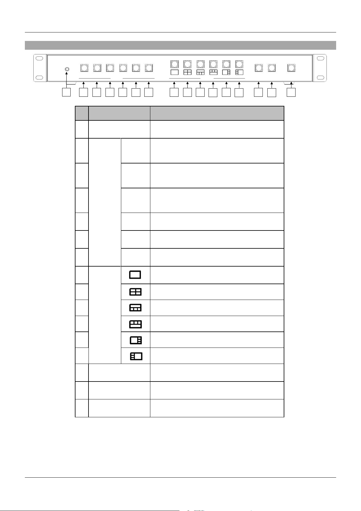
1
IR Receiver
Receives signals from the remote control
transmitter
2
INPUT*
HDMI1
Press to select the HDMI 1 input in full screen
Press to select HDMI 1 audio in multi-view
screen
3
HDMI2
Press to select the HDMI 2 input in full screen
Press to select HDMI 2 audio in multi-view
screen
4
HDMI3
Press to select the HDMI 3 input in full screen
Press to select HDMI 3 audio in multi-view
screen
5
HDMI4
Press to select the HDMI 4 input in full screen
6
DP
Press to select the DP input in full screen
Press to select DP audio in multi-view screen
7
VGA
Press to select the VGA input in full screen
Press to select VGA audio in multi-view screen
8
LAYOUT*
Press to select Layout A (full screen mode)
9 Press to select Layout B
10 Press to select Layout C
11 Press to select Layout D
12 Press to select Layout E
13
Press to select Layout F
14
INPUT SWAP
Toggle the input source in Layout B, C, D, E and
F mode
15
PANEL LOCK
Press to lock or unlock the front panel buttons
16
STANDBY
Press to put the system into standby mode or
wake up the system
INPUT
SWAP
PANEL
LOCK
STANDBY
1
2 3 4
5 6 7 8 9
10
11
12
13
14
15
16
Front Panel Operation
HDMI1 HDMI2 HDMI3
HDMI4 DP VGA
INPUT LAYOUT
* Please see Appendix 1 and Appendix 2
Page 6
User Manual English
No.
Feature
Description
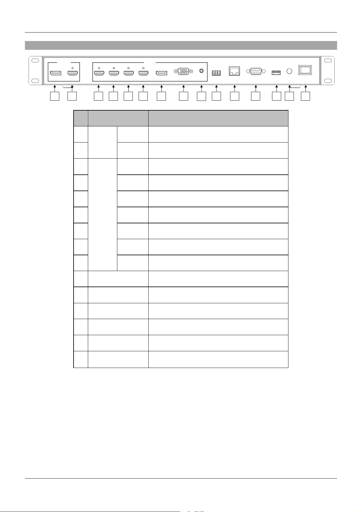
1
OUTPUT
DP
Connect to the DP display device, video fellows
window A.
2
HDMI
Connect to the HDMI display device, connector on
rear panel with locking
3
INPUT
HDMI1
Connect to the HDMI source, connector on rear
panel with locking
4
HDMI2
Connect to the HDMI source, connector on rear
panel with locking
5
HDMI3
Connect to the HDMI source, connector on rear
panel with locking
6
HDMI4
Connect to the HDMI source, , connector on rear
panel with locking
7
DP
Connect to the DP source
8
VGA
Connect to the VGA source
9
AUDIO
Connect to the audio source
10
AUDIO OUT
Connect to the audio amplifier
11
ETHERNET
Connect to PC, NB or other Controller through IP
network
12
RS232/TELNET
Connect to PC, NB or other Controller
13
USB
Connect to PC for firmware upgrade
14
12V DC
Connect to the 12V/2A power supply, connector
on rear panel with locking barrel
15
POWER ON/OFF
Power switch for turn ON or OFF the
processor switch
USB
12V DC
VGA
HDMI4
AUDIO
RS232
ETHERNET
AUDIO
OUT
HDMI
HDMI1
10
11
12
13
14
15 1 2 3 4 5 6 7 8
9
Rear Panel Operation
OUTPUT
DP
HDMI2
HDMI3
INPUT
DP
POWER
ON/OFF
Page 7

User Manual English
No.
Feature
Description
1
Standby
Press to set system into standby mode or wake
up the system
2
Lock
Press to Lock or unlock the front panel buttons
3
Input*
H-1
Select HDMI 1 in full screen mode
Select HDMI 1 audio in multiview mode
H-2
Select HDMI 2 in full screen mode
Select HDMI 2 audio in multiview mode.
H-3
Select HDMI 3 in full screen mode
Select HDMI 3 audio in multiview mode
H-4
Select HDMI 4 in full screen mode
3
Input*
DP
Select DP in full screen mode
Select DP audio in multiview mode
VGA
Select VGA in full screen mode
Select "VGA" for audio in multiview mode
IR Remote Control
Page 8

User Manual English
No.
Feature
Description
4
Layout*
Select the Layout A (full screen mode)
Select the Layout B
Select the Layout C
Select the Layout D
Select the Layout E
Select the Layout F
5
Input Swap*
Toggle the Input source in Layout B, C, D, E
and F mode
6
Info.
System information
7
OK
Reserved
Up
Reserved
Down
Reserved
Left
Reserved
Right
Reserved
8
Rotate*
Rotate the video display R90o/ L90o in full
screen mode
9
Flip
Flip display screen in full screen mode
10
Custom
Layout*
1
Select the custom screen layout 1
2
Select the custom screen layout 2
3
Select the custom screen layout 3
4
Select the custom screen layout 4
5
Select the custom screen layout 5
6
Select the custom screen layout 6
10
Custom
Layout*
7
Select the custom screen layout 7
8
Select the custom screen layout 8
11
Set
Red
Set output resolution to 3840x2160@60Hz(with
Auto Detect)
Green
Set output resolution to 3840x2160@30Hz
Yellow
Set output resolution to 1920x1080@60Hz
Blue
Set output resolution to 1280x720@60Hz
* Please see Appendix 1 and Appendix 2
Page 9

User Manual English
Video Layout Modes
Layout A – The single selected input will be displayed. This is a full
screen output
Layout B – The Inputs selected will be displayed in a 2 x 2 grid.
Layout C – The Inputs selected will be displayed with one large window
along the top with three smaller underneath.
Layout D – The Inputs selected will be displayed with three small along
the top and 1 large window underneath.
Layout E – the Inputs selected under Channels 1 – 4 will be displayed in
a 4 x 1 grid.
Layout F – the Inputs selected under Channels 1 – 4 will be displayed in
a 4 x 1 grid.
Page 10

User Manual English
No.
Feature
Description
1
System
FW version
System firmware version
2
Reboot
Reboot the processor switch
3
Network
Ethernet
Type
Change the network type to Static IP or
DHCP
Press “Confirm” after setting to finish or press
“Cancel” to ignore the modification.
Web GUI
Please note that the unit uses the following IP settings by default, ensure that the device you are using to access
the web GUI is on the same network with a compatible IP range.
IP Address - the default value of the unit is 192.168.1.202
Subnet Mask - the default value of the unit is 255.255.255.0
You can now use your browser to access the web GUI by using the IP address of the unit. This can be changed
under the system settings on the GUI, you can choose from your own manual IP address or DHCP.
Page 11

User Manual English
No.
Feature
Description
1
Output
Setting
Resolution
Select output resolution
1: Auto (default)
2: 3840x2160@60Hz
3: 3840x2160@50Hz
4: 3840x2160@30Hz
5: 1920x1080@60Hz
6: 1280x720@60Hz
7: 480p@60Hz
Press “Confirm” after setting to finish or press
“Cancel” to ignore the modification.
2
Audio
Source*
Select audio output source
1: Window A (default)
2: HDMI1
3: HDMI2
4: HDMI3
5: DP
6: VGA
7: Mute
Press “Confirm” after setting to finish or press
“Cancel” to ignore the modification.
3
Full
Screen
Setting
Flip
Flip video display in full screen mode
1: On
2: Off (default)
Press “Confirm” after setting to finish or press
“Cancel” to ignore the modification.
4
Rotate**
Rotate video display in full screen mode
1: Off (default)
2: L90o
3: R90o
Press “Confirm” after setting to finish or press
“Cancel” to ignore the modification.
5
Color
Setting
Color
Setting
Modify color setting
1: 50 (default)
2: 0~100
Press “Confirm” after setting to finish or press
“Cancel” to ignore the modification.
* HDMI4 audio NA in multi-view and custom layout mode
** Please see Appendix 1
Page 12

User Manual English
No.
Feature
Description
6
Layout
Setting
Pre-defined*
Select display layout type on monitor
1: Layout A (default, full screen)
2: Layout B
3: Layout C
4: Layout D
5: Layout E
6: Layout F
Press “Confirm” after setting to finish or
press “Cancel” to ignore the modification.
7
Window
Info.
Main Screen: Window A
Sub Screen: Window B, Window C,
Window D
Window A input source: HDMI1 (default)
Window B input source: HDMI2 (default)
Window C input source: HDMI3 (default)
Window D input source: DP (default)
Press “Confirm” after setting to finish or
press “Cancel” to ignore the modification.
8
Layout
Setting
Layout A
Gear icon
Select Input Source
1: HDMI1 (default)
2: HDMI2
3: HDMI3
4: HDMI4
5: DP
6: VGA
* Please see Appendix 1 and Appendix 2
Page 13

User Manual English
No.
Feature
Description
9
Layout
Setting
Custom *
Select display custom layout type on
monitor
Press “Confirm” after setting to finish or
press “Cancel” to ignore the modification.
10
Layout
Setting
Window **
Window Information in upper left side of
the window.
1. Window name: Window A, B, C and D
2. Blue mark: Indicates the Input source
(it can be changed in “Gear icon”).
3. Orange mark: Indicates the display
layer.
The Window A to D position can be
moved when clicking mouse left button.
The size of Window A to D can be
modified when moving mouse cursor to
right or bottom of the window corner.
11
Gear icon
Select Input Source
1: HDMI1 (default)
2: HDMI2
3: HDMI3
4: DP
5: VGA
12
x icon
Press to close the window.
13
Open/Close
Window
Press to open or close the window.
* Please see Appendix 1 and Appendix 2
** “Orange mark”: layer definition.
Page 14

User Manual English
Factory Reset / Web GUI
Press the “Load Default” icon to reset to the default settings for the Web UI.
Page 15

User Manual English
Command
Description
Parameter
SPOW 0/1
SET THE UNIT POWER ON/OFF
0=OFF,1=ON
RPOW
SHOW CURRENT POWER STATE
SRES 0~6
SET OUTPUT RESOLUTOIN
0: AUTO (Default)
1: 3840x2160@60
2: 3840x2160@30
3: 1920x1080@60
4: 1280x720@60*
5: 640x480@60*
6: 3840x2160@50
RRES
SHOW CURRENT OUTPUT RESOLUTION
SIOSDD
ENABLE ONSCREEN INFORMATION
DISPLAY
SBRI N
SET BRIGHTNESS VALUE FOR OUTPUT
N=0~100,
Default 50
RBRI
SHOW BRIGHTNESS CURRENT VALUE
FOR OUTPUT
SCON N
SET CONTRAST VALUE FOR OUTPUT
N=0~100,
Default 50
RCON
SHOW CONTRAST CURRENT VALUE!!
SSAT N
SET SATURTATION VALUE FOR OUTPUT
N=0~100,
Default 50
RSAT
SHOW SATURTATION CURRENT VALUE
SHUE N
SET HUE VALUE FOR OUTPUT
N=0~100,
Default 50
RHUE
SHOW HUE CURRENT VALUE
SIMRE 0~4
RESET COLOR SETTING VALUE TO
DEFAULT
0 = ALL,
BRIGHTNESS+CONTRAS
T+SATURATION+HUE
1=BRIGHTNESS,
2=CONTRAST,
3=SATURATION,
4=HUE,
SIN2CH N M**
SET INPUT SOURCE M TO WINDOW N
WINDOW N=1~4,
1: A, 2: B, 3: C, 4: D
INPUT SOURCE M=1~6,
1:HDMI1, 2:HDMI2,
3:HDMI3, 4:HDMI4, 5:DP,
6:VGA
SHSIZE N M**
SET WINDOW HORIZONTAL SIZE
WINDOW N=1~4,
1: A, 2: B, 3: C, 4: D
HORZONTAL SIZE
M=1~60
Serial / TELNET Commands and settings
Serial Port Settings:
Baud rate: 115200
Data bits: 8
Stop bits: 1
Parity: None
Flow control: None
Commands:
Page 16

User Manual English
Command
Description
Parameter
RHSIZE**
SHOW WINDOW HORIZONTAL SIZE
CURRENT VALUE
WINDOW A~D=WINDOW 1~4
HORIZONTAL SIZE 1~60
SVSIZE N M**
SET IMAGE VERTICAL SIZE
WINDOW N=1~4,
1: A, 2: B, 3: C, 4: D
VERTICAL SIZE M=1~60
RVSIZE**
SHOW WINDOW VERTICAL SIZE
CURRENT VALUE
WINDOW A~D=WINDOW 1~4
VERTICAL SIZE 0~17
SHPOS N M**
SET HORIZONTAL POSITION OF
SPECIFIED CHANNEL
WINDOW N=1~4,
1: A, 2: B, 3: C, 4: D
HORIZONTAL POSITION
M=0~59
RHPOS**
SHOW WINDOW HORIZONTAL POSITION
CURRENT VALUE
WINDOW A~D=WINDOW 1~4
HORIZONTAL SIZE 0~59
SVPOS N M**
SET VERTICAL POSITION OF SPECIFIED
WINDOW
WINDOW N=1~4,
1: A, 2: B, 3: C, 4: D
VERTICAL POSITION
M=0~59
RVPOS**
SHOW WINDOW VERTICAL POSITION
CURRENT VALUE
WINDOW A~D=WINDOW 1~4
VERTICAL SIZE 0~59
SWIN N M**
SET OUTPUT WINDOW ON/OFF
WINDOW N=1~4,
1: A, 2: B, 3: C, 4: D
M=0/OFF, 1/ON
RWIN N**
SHOW OUTPUT WINDOW
WINDOW N=0~4,
1: A, 2: B, 3: C, 4: D
0: ALL
SPRI N M**
SET WINDOW LAYER PRIORITY
WINDOW N=1~4,
1: A, 2: B, 3: C, 4: D
LAYER PRIORITY
M= 1~4,
1=BOTTOM, 2=LAYER 3,
3=LAYER2, 4=UPPER
RPRI N**
SHOW WINDOW LAYER PRIORITY
WINDOW N=0~4,
1: A, 2: B, 3: C, 4: D
0: ALL
SRECALL 1~14
SET AN OUTPUT WINDOW TO LAYOUT
A~CUSTOM 8.
1 = LAYOUT A,
2 = LAYOUT B,
3 = LAYOUT C,
4 = LAYOUT D,
5 = LAYOUT E,
6 = LAYOUT F,
7 = CUSTOM 1,
8 = CUSTOM 2,
9 = CUSTOM 3,
10 = CUSTOM 4,
11 = CUSTOM 5,
12 = CUSTOM 6,
13 = CUSTOM 7,
14 = CUSTOM 8
SROTATE 0~4
SET VIDEO ROTATION
SRECALL 1 MUST BE ENABLE BEFORE
SROTATE
0=ROTATE OFF,
1 = L90,
2 = R90,
3 = Flip on,
4 = Flip off
Default 0
RROTATE
SHOW VIDEO ROTATION CURRENT
SIPM 0/1
SET IP MODE TO DHCP OR STATIC
0=DHCP, 1=STATIC,
Default 1
Page 17

User Manual English
Command
Description
Parameter
RIPM
SHOW CURRENT IP MODE
SIPADD N M X Y
SET STATIC IP ADDRESS
N=0~255, M=0~255,
X=0~255, Y=0~255
RIPADD
SHOW STATIC CURRENT IP ADDRESS
SMAADD N M X
Y
SET STATIC SUBNET ADDRESS
N=0~255, M=0~255,
X=0~255, Y=0~255
RMAADD
SHOW STATIC CURRENT SUBNET
ADDRESS
SGAADD N M X Y
SET STATIC GATEWAY ADDRESS
N=0~255, M=0~255,
X=0~255, Y=0~255
RGAADD
SHOW STATIC CURRENT GATEWAY
ADDRESS
IPCONFIG
SHOW ETHERNET ADDRESS
DEFAULT
RESET THE UNIT TO FACTORY
DEFAULTS
SMUTE 0/1
SET MUTE AUDIO
0=UNMUTE, 1= MUTE
RMUTE
SHOW CURRENT MUTE
SAUDIO N
SET OUTPUT AUDIO TO SPECIFIED
SOURCE
AUDIO SELECT N=0~6,
0 = WINDOW A,
1 = HDMI1,
2 = HDMI2,
3 = HDMI3,
4 = reserved,
5 = DP,
6 = VGA
RAUDIO
SHOW OUTPUT AUDIO SOURCE
SWICORE**
RESET THE WINDOW A
~ WINDOW D SETTINGS TO FACTORY
DEFAULTS
RFW
SHOW FIRMWARE VERSION
REBOOT
SYSTEM REBOOT
READEDID
READ EDID INFO FROM SINK DEVICE
* Please see Appendix 1 for the condition for this output resolution.
** This command only works on custom layout.
Page 18

User Manual English
Input
Resolution
Layout A
Layout B
Layout C
Layout D
Layout E
Layout F
Custom
Layout
4K60
Rotate NA
INPUT SWAP
NA
Rotate NA
Flip NA
HDMI4 NA
Rotate NA
Flip NA
HDMI4 NA
Rotate NA
Flip NA
HDMI4 NA
Rotate NA
Flip NA
HDMI4 NA
Rotate NA
Flip NA
HDMI4 NA
Rotate NA
Flip NA
HDMI4 NA
4K30
Rotate NA
INPUT SWAP
NA
Rotate NA
Flip NA
HDMI4 NA
Rotate NA
Flip NA
HDMI4 NA
Rotate NA
Flip NA
HDMI4 NA
Rotate NA
Flip NA
HDMI4 NA
Rotate NA
Flip NA
HDMI4 NA
Rotate NA
Flip NA
HDMI4 NA
1080p
INPUT SWAP
NA
Rotate NA
Flip NA
HDMI4 NA
Rotate NA
Flip NA
HDMI4 NA
Rotate NA
Flip NA
HDMI4 NA
Rotate NA
Flip NA
HDMI4 NA
Rotate NA
Flip NA
HDMI4 NA
Rotate NA
Flip NA
HDMI4 NA
720p
INPUT SWAP
NA
Rotate NA
Flip NA
HDMI4 NA
Rotate NA
Flip NA
HDMI4 NA
Rotate NA
Flip NA
HDMI4 NA
Rotate NA
Flip NA
HDMI4 NA
Rotate NA
Flip NA
HDMI4 NA
Rotate NA
Flip NA
HDMI4 NA
480p
INPUT SWAP
NA
Rotate NA
Flip NA
HDMI4 NA
Rotate NA
Flip NA
HDMI4 NA
Rotate NA
Flip NA
HDMI4 NA
Rotate NA
Flip NA
HDMI4 NA
Rotate NA
Flip NA
HDMI4 NA
Rotate NA
Flip NA
HDMI4 NA
Output
Resolution
Layout A
Layout B
Layout C
Layout D
Layout E
Layout F
Custom
Layout
4K60
4K30
1080p
720p
HDMI
Output NA
HDMI
Output NA
HDMI
Output NA
480p
HDMI
Output NA
HDMI
Output NA
HDMI
Output NA
HDMI
Output NA
HDMI
Output NA
HDMI
Output NA
Screen Layout
Layout A
Indicator
Layout B
Indicator
Layout C
Indicator
Layout D
Indicator
Layout E
Indicator
Layout F
Indicator
Layout A
V
Layout B
V
Layout C
V
Layout D
V
Layout E
V
Layout F
V
Custom
Layout
V
V
Appendix 1: Function NA list
Appendix 2: Front Panel Screen Layout Indicator
Page 19

CE/FCC Statement
CE Certification
This equipment complies with the requirements relating to Electromagnetic Compatibility Standards.
It has been manufactured under the scope of RoHS compliance.
CE Konformitätserklärung
Dieses Produkt entspricht den einschlägigen EMV Richtlinien der EU für IT-Equipment und darf nur
zusammen mit abgeschirmten Kabeln verwendet werden.
Diese Geräte wurden unter Berücksichtigung der RoHS Vorgaben hergestellt.
Die formelle Konformitätserklärung können wir Ihnen auf Anforderung zur Verfügung stellen
FCC Certification
This equipment has been tested and found to comply with the limits for a Class B digital device, pursuant
to part 15 of the FCC Rules. These limits are designed to provide reasonable protection against harmful
interference in a residential installation.
You are cautioned that changes or modification not expressly approved by the party responsible for
compliance could void your authority to operate the equipment.
This device complies with part 15 of the FCC Rules.
Operation is subject to the following two conditions:
1. This device may not cause harmful interference, and
2. This device must accept any interference received, including interference that may cause undesired
operation.
LINDY Herstellergarantie – Hinweis für Kunden in Deutschland
LINDY gewährt für dieses Produkt über die gesetzliche Regelung in Deutschland hinaus eine zweijährige
Herstellergarantie ab Kaufdatum. Die detaillierten Bedingungen dieser Garantie finden Sie auf der LINDY Website
aufgelistet bei den AGBs.
Hersteller / Manufacturer (EU):.
LINDY-Elektronik GmbH LINDY Electronics Ltd
Markircher Str. 20 Sadler Forster Way
68229 Mannheim Stockton-on-Tees, TS17 9JY
GERMANY United Kingdom
Email: info@lindy.com , T: +49 (0)621 470050 postmaster@lindy.co.uk , T: +44 (0)1642 754000
Page 20

Recycling Information
WEEE (Waste of Electrical and Electronic Equipment),
Recycling of Electronic Products
Europe, United Kingdom
In 2006 the European Union introduced regulations (WEEE) for the collection and recycling of all waste electrical
and electronic equipment. It is no longer allowable to simply throw away electrical and electronic equipment.
Instead, these products must enter the recycling process.
Each individual EU member state has implemented the WEEE regulations into national law in slightly different
ways. Please follow your national law when you want to dispose of any electrical or electronic products. More
details can be obtained from your national WEEE recycling agency.
Battery Remark:
Do not put empty batteries in your domestic waste bin as they will not be recycled. Empty batteries can be returned
for recycling at our trade counter or at your local household recycling centre.
The raw materials enclosed in batteries such as Zinc, Iron and Nickel can be reused to a very large proportion. The
recycling of batteries and disused/obsolete electronic equipment is one of the most efficient environment protection
actions you can easily take.
Germany / Deutschland Rücknahme Elektroschrott und Batterie-Entsorgung
Die Europäische Union hat mit der WEEE Direktive Regelungen für die Verschrottung und das Recycling von
Elektro- und Elektronikprodukten geschaffen. Diese wurden im Elektro- und Elektronikgerätegesetz – ElektroG in
deutsches Recht umgesetzt. Das Entsorgen von Elektro- und Elektronikgeräten über die Hausmülltonne ist
verboten! Diese Geräte müssen den Sammel- und Rückgabesystemen zugeführt werden! Dort werden sie
kostenlos entgegen genommen. Die Kosten für den weiteren Recyclingprozess übernehmen die Gerätehersteller.
LINDY bietet deutschen Endverbrauchern ein kostenloses Rücknahmesystem an, beachten Sie bitte, dass
Batterien und Akkus den Produkten vor der Rückgabe an das Rücknahmesystem entnommen werden müssen und
über die Sammel- und Rückgabesysteme für Batterien separat entsorgt werden müssen. Ausführliche
Informationen zu diesen Themen finden Sie stets aktuell auf der LINDY Webseite im Fußbereich.
France
En 2006, l'union Européenne a introduit la nouvelle réglementation (DEEE) pour le recyclage de tout équipement
électrique et électronique.
Chaque Etat membre de l’ Union Européenne a mis en application la nouvelle réglementation DEEE de manières
légèrement différentes. Veuillez suivre le décret d’application correspondant à l’élimination des déchets électriques
ou électroniques de votre pays.
Remarque sur les piles et batteries
En tant que consommateur final, vous êtes tenus de restituer toutes les piles et batteries usagées. Il est clairement
interdit de les jeter avec les ordures ménagères ! Les piles et batteries contenant des substances nocives sont
marquées par le symbole ci-dessus. Vous pouvez déposer gratuitement vos piles ou batteries usagées dans les
centres de collecte de votre commune, dans nos succursales ou dans tous les points de vente de piles ou
batteries. Vous respecterez ainsi la loi et contribuerez à la protection de l'environnement !
Italy
Nel 2006 l’unione europea ha introdotto regolamentazioni (WEEE) per la raccolta e il riciclo di apparecchi elettrici
ed elettronici. Non è più consentito semplicemente gettare queste apparecchiature, devono essere riciclate. Ogni
stato membro dell’ EU ha tramutato le direttive WEEE in leggi statali in varie misure. Fare riferimen to alle leggi del
proprio Stato quando si dispone di un apparecchio elettrico o elettronico.
Per ulteriori dettagli fare riferimento alla direttiva WEEE sul riciclaggio del proprio Stato.
LINDY No 38156
1st Edition, January 2018
lindy.com
 Loading...