

Page 1
Tested to Comply with
FCC Standards
For Home and Office Use!
HDMI 4x4 Matrix
with Video Wall Scaling
User Manual English
Benutzerhandbuch Deutsch
Manuel Utilisateur Français
Manuale Italiano
No. 38131
www.lindy.com
© LINDY Group – SECOND EDITION
Page 2

User Manual English
Introduction
Thank you for purchasing the LINDY HDMI Video Wall 4x4 Matrix. The HDMI Video Wall 4x4 Matrix allows
the signals from four different sources to be freely selected and arranged on 4 displays (TV, Monitor or
Projector), in one of three output modes; Video Wall, Matrix and dual.
This flexible feature rich product has been designed to be used in a number of different applications, such
as:
Public Advertisement
Digital Presentation
Broadcasting & Control
Surveillance & Control
Conference & Meeting Room
Package Contents
HDMI Video Wall 4x4 Matrix
IR Remote Control
Multi-Country 12V 3A Power Supply (UK/EU/US/AUS)
Driver CD
This manual
Features
Allows 4 HDMI Inputs to be displayed in 3 different modes across 4 HD displays
Video Wall Mode – Display an HDMI source across a 2x2 video wall
Matrix Mode – Display any HDMI source on any HDMI display
Dual Mode – Display 2 sources on a single HDMI display
Seamless switching between HDMI sources
User definable output scaling
Controlled via On-panel controls, IR Remote, RS-232 and Telnet
Bezel correction to aide screen blending
Adjustable picture contrast, brightness, saturation and hue
Memory function to store 4 user determined configurations
Can be used with LINDY HDMI extenders to reach remote displays
Specification
Input ports: 4 x HDMI Female
Input resolution: 480i – 1080p*
Output ports: 4 x HDMI Female
Output resolution: 480p – 1080p*
Audio support: LPCM 2CH, 6CH, 8CH, AC3, DTS, Dolby Digital Plus, Dolby TrueHD & DTS-HD
Control Ports: RJ45 (Telnet) & Serial 9 Way Male (RS-232)
Video bandwidth: 225MHz/6.75Gbps
Power consumption: 15W
Weight: 2.2Kg
Dimensions: 436x247x44mm (WxDxH)
*Please Note: For additional information regarding the exact resolution/timing combinations which are supported for input and
output please refer to the Timings section at the end of this manual.
Page 3
User Manual English
OUTPUT
A B C
D
INPUT 1 2 3 4
SAVE
RECALL
LOCK
MATRIX/
DUAL/WALL
POWER
MENU
-
+
XGA
720P
1 2 3 4 5 8 9 7 6
Overview & Operation
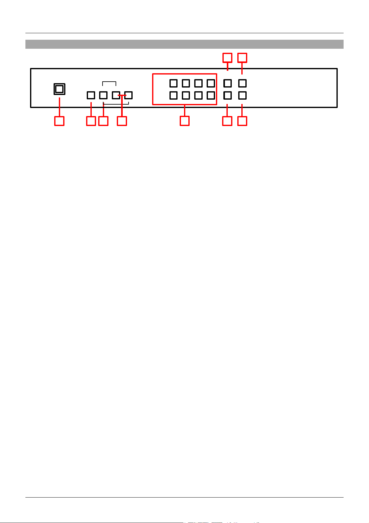
Front Panel
1. IR Window
Receives IR commands from the supplied IR Remote
2. Power
Switch the Matrix On/Off
3. Menu
Press to launch the OSD menu
Press to make a menu selection in the OSD
Press along with “-“ to set the Output to 720p@60Hz
Press along with “+” to set the Output to 1024x768@60Hz
4. -/+ Buttons
Use these buttons to move up and down in the OSD
5. Channel Input (1 – 4) / Channel Output (A – D) Selection
In Matrix Mode select an Output by pressing one of the buttons marked A – D, then select the Input
to be used by pressing one of the buttons marked 1 – 4. Repeat this for each Output. Each Output
can independently display any of the Inputs according to your selection.
In Dual Mode there are two groups, Dual A (Outputs A & B) and Dual B (Outputs C & D). To set up
Dual A select Output A then select the first input by pressing one of the buttons marked 1 – 4. Now
select Output B then select the second input by pressing one of the buttons marked 1 – 4, without
duplicating your initial selection. Your two input selections will now be shown on Output A and Output
B. For Dual B repeat this for Output C and D as required. Press and hold Output A or B for 3 seconds
to select the audio input for Dual A, or Output C or D to select the audio input for Dual B.
In Video Wall Mode select the input to be displayed across the 4 displays (2x2 configuration) by
selecting Input 1 – 4. Audio will be available through Output A only.
6. Matrix / Dual / Wall Mode
Press this button to switch between the different modes. When Matrix Mode is selected the button will
stay constantly illuminated, for Dual Mode the button will not illuminate and for Video Wall Mode the
button will blink on/off.
7. Lock
Press this button once to lock the keypad and remote control, press and hold the button again for 3
seconds to release the lock.
8. Save
Once you have configured the Matrix (Mode selection, Input/Output combinations etc.) press the Save
button, the Input 1 – 4 buttons will then illuminate. Now press one of the Input buttons to save your
configuration. Pressing Input 1 would save the configuration to slot 1, this can then be recalled using
the Recall button (see below) or by pressing Fav.1 on the IR Remote.
9. Recall
Press the Recall button, the Input 1 – 4 buttons will then illuminate. Now select which saved
configuration you want to recall by pressing Input button 1/2/3/4.
Page 4

User Manual English
1 2 3 4 5
6
HDMI IN
1 2 3 4 A B C
D
HDMI OUT
CONTROL
RS232
DC 12V
USB
SERVICE
ONLY
INFO
POWER
Out A
In 1
Matrix
Out B
In 2
Dual
Out C
In 3
TV Wall
Out D
In 4
Lock
Mute
OK
Exit
Menu
1024x768
Save
FAV.1
720p
1080p
FAV.2
AL
AR
FAV.3
FAV.4
BR
BL
1 2 3 4 5
6
7 8 9
10
11
13
12
Rear Panel
1. HDMI In 1 – 4
Connect your HDMI sources devices such as PC, Blu-ray etc to these ports
2. HDMI Out A – D
Connect your HDMI displays to these ports
3. Control
Connect to an Ethernet network for Telnet control
4. USB Service Only
Reserved for Factory use only
5. RS-232
For connection to a PC/Notebook or Remote Control Processing unit
6. DC 12V
Connect the supplied 12V power supply here
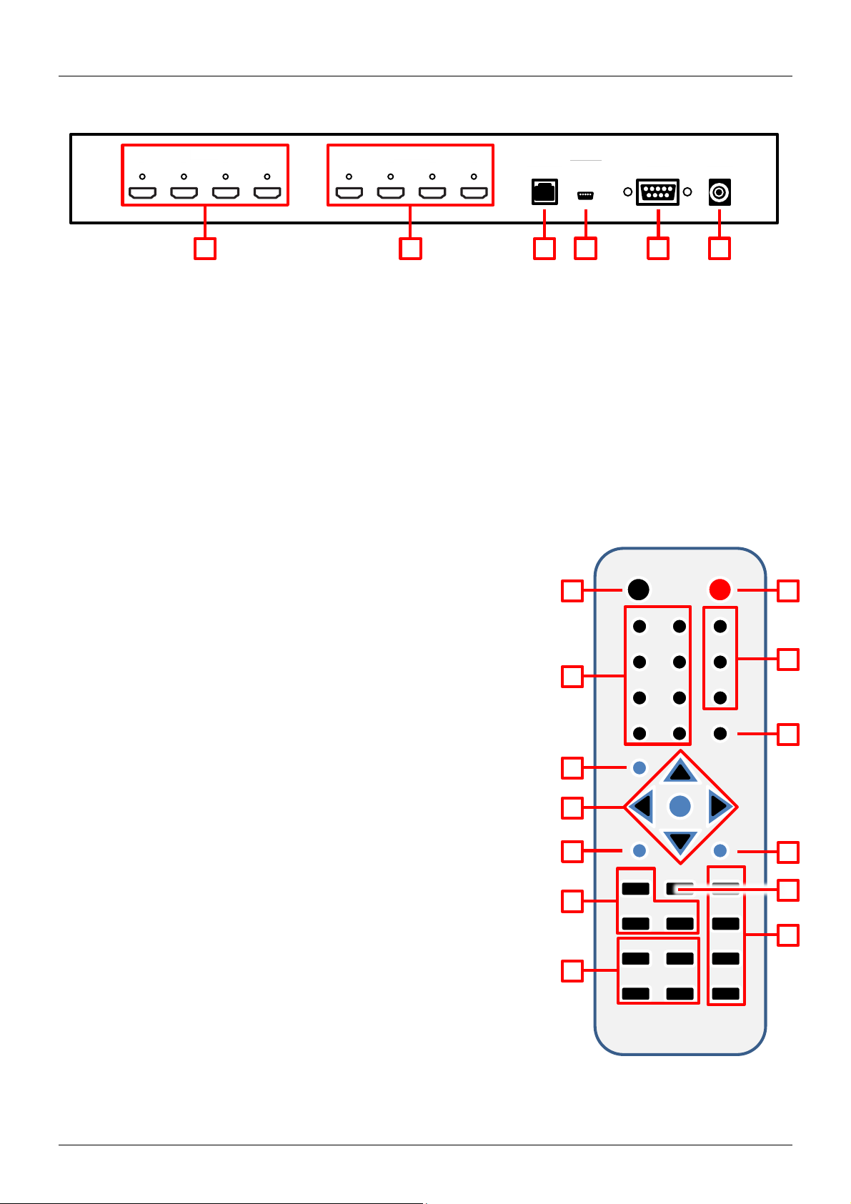
Remote Control
1. Power
Switch the Matrix On/Off
2. Info
Press to display the Matrix’s firmware version
3. Output A – D & Input 1 – 4
Provide the same function as the front panel buttons
4. Matrix/Dual/Wall Mode Selection
Provide the same function as the front panel buttons
5. Lock
Provides the same function as the front panel button
6. Mute
Press to Mute audio playback from the HDMI output port
7. Navigation/Selection Buttons
Press to navigate the OSD and make selections
8. Menu
Press to enter the OSD menu
9. Exit
Press to exit the OSD menu
10. Output Resolution
Press to quickly change the Output resolution
11. Dual Mode Audio
Switch between Left/Right input source audio, for Dual A or Dual B
12. Save
Provides the same function as the front panel button
13. FAV. 1 – 4
Recalls the settings saved to the corresponding save location
Page 5
User Manual English
Set-Top Box
Blu-Ray Player
HDMI
Cable
HDMI
Cable
HDMI
Cable
HDMI
Cable
HDMI
Cable
HDMI
Cable
RJ45
Cable
9 Way Serial
PC
TV/Display
TV/Display
TV/Display
TV/Display
Notebook
Notebook
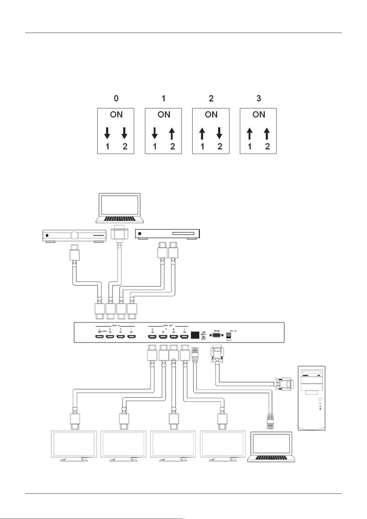
By removing the battery cover of the IR Remote you can access a set of dip switches which allow you to
change the default IR address, as may be required if multiple Matrixes’ are used in close proximity or if
there is interference with another IR device. Before changing the dip switch setting from its default of 0,
please change the IR setting on the Matrix first. Enter the OSD and then select Others, now select IR
Address and select the desired address 0 – 3.
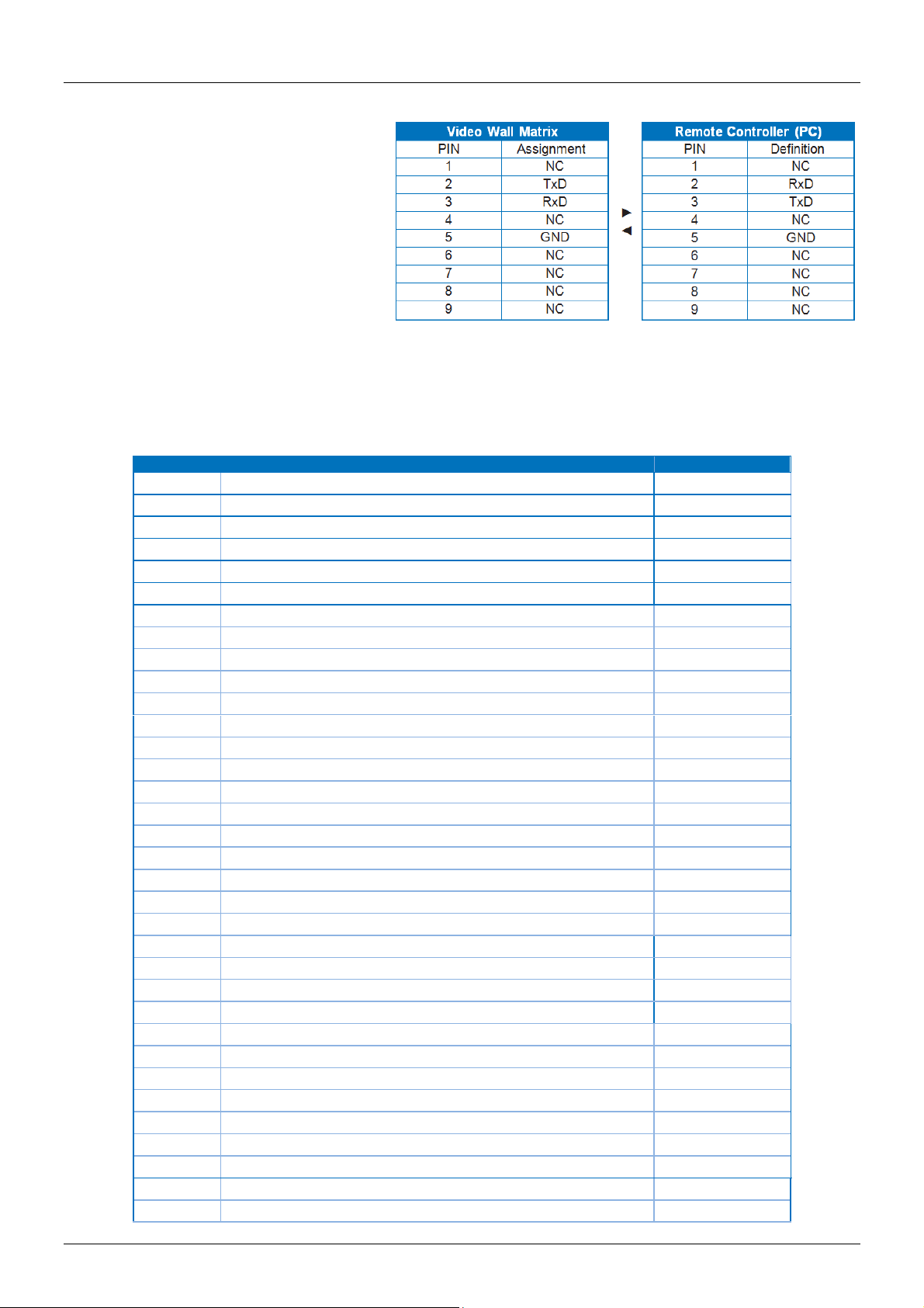
Connection Diagram
Cable
Page 6
User Manual English
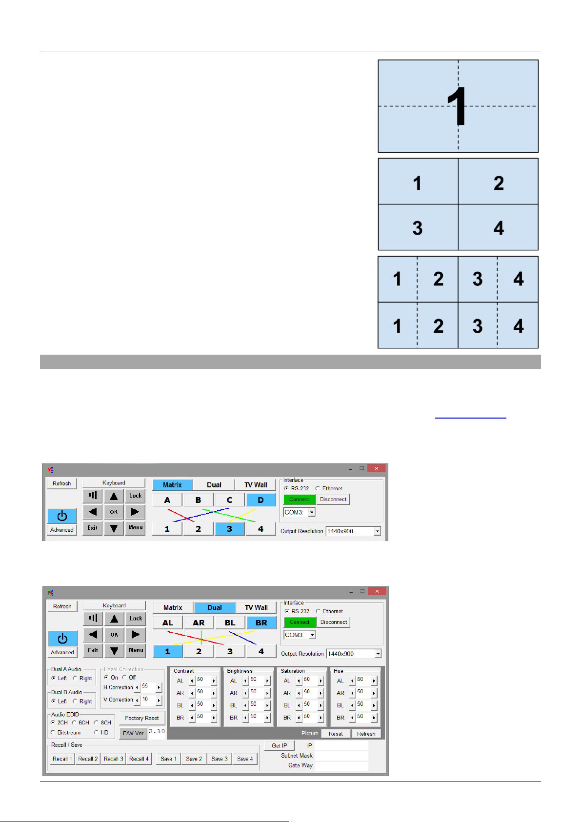
Video Output Modes
Video Wall
Displays a single user definable HDMI source across a 2x2
video wall.
Video Matrix
Display any HDMI source on any HDMI display.
Dual Output
Display 2 HDMI sources on a single HDMI Output. Outputs
are grouped as follows Dual A (Outputs A & B) and Dual B
(Outputs C & D).
RS-232, Telnet & OSD Control
RS-232 & Telnet Control
The Matrix may also be controlled via PC software which can be downloaded from www.lindy.com, or
using Hyper Terminal. The PC software provides a graphical interface for control as shown below:
Simple Control Panel
Full Function Control Panel
Page 7
User Manual English
Command
Active
4x4 Matrix Return
ASP000
Aspect Ratio is Full
ASP000
ASP001
Aspect ratio is 4:3 TV
ASP001
ASP002
Aspect Ratio is 16:9 TV
ASP002
ASP003
Aspect Ratio is 16:10 TV
ASP003
ASP004
Aspect Ratio is to Keep Ratio
ASP004
ASP999
Check Aspect Ratio Status
ASP999
AUA001
Dual A Audio channel in Left side
AUA001
AUA002
Dual A Audio channel in Right side
AUA002
AUA999
Check Dual A audio channel status
AUA???
AUB001
Dual B Audio channel in Left side
AUB001
AUB002
Dual B Audio channel in Right side
AUB002
AUB999
Check Dual B audio channel status
AUB???
AUD000
Audio output Off
AUD000
AUD001
Audio output On
AUD001
AUD999
Check audio on/off status
AUD???
AUE000
Audio EDID is LPCM 2CH
AUE000
AUE001
Audio EDID is LPCM 6CH
AUE001
AUE002
Audio EDID is LPCM 8CH
AUE002
AUE003
Audio EDID is BITSTREAM
AUE003
AUE004
Audio EDID is HD
AUE004
AUE999
Check audio EDID setting
AUE???
AUQ001
Quad Audio from Quad 1
AUQ001
AUQ002
Quad Audio from Quad 2
AUQ002
AUQ003
Quad Audio from Quad 3
AUQ003
AUQ004
Quad Audio from Quad 4
AUQ004
AUQ999
Check Quad Audio Setting
AUQ???
BEZ000
Bezel Correction OFF
BEZ000
BEZ001
Bezel Correction ON
BEZ001
BEZ999
Check bezel correction on/off status
BEZ???
BEH???
Horizontal (H) Bezel correction???=000 - Maximum
BEH???
BEH998
Check the current Horizontal(H) Bezel correction Maximum value
BEH???
BEH999
Check the current Horizontal(H) Bezel correction setting value
BEH???
BEV???
Vertical (V) Bezel correction???=000- Maximum
BEV???
BEV998
Check the current Vertical(V) Bezel correction Maximum value
BEV???
RS-232 Protocols
Baud Rate: 115200bps Data Bit: 8 bits
Parity: None
Flow Control: None
Stop Bit: 1
Telnet Setting
Use TCP/IP (Port 23) for Telnet communication.
RS-232 & Telnet Commands
Page 8

User Manual English
Command
Active
4x4 Matrix Return
BEV999
Check the current Vertical(V) Bezel correction setting value
BEV???
BRI???
Setting Brightness
No response
???=000-100 for matrix mode
???=(000-100)+200*(OUT No.-1) for dual/tv wall mode
For example: OUT B set the Brightness value to 57 =(57)+200*(2-1) = 257
BRI99?
Check current Brightness value
BRI???
99?=999 for matrix mode
99?=991-994=OUT1-4 for dual/tv wall mode
CAL???
RECALL FAV. ???=001-004=FAV.1-4
CAL???
CON???
Setting Contrast
No Response
CON999
Command setting same as Brightness(BRI)
CON???
DUL001
Set Dual mode to PoP
DUL001
DUL002
Set Dual mode to PiP
DUL002
DUL003
Check Dual mode status
DUL999
EGW999
RS232 only, check current Ethernet
Gateway Address
aaa.bbb.ccc.ddd
EIP999
RS232 only, check current Ethernet IP
Address
aaa.bbb.ccc.ddd
EMK999
RS232 only, check current Ethernet
Subnet Mask Address
aaa.bbb.ccc.ddd
HLP999
Show Command List
Command List
HPI0xy
HDCP Input setting
x=1~4=IN 1~4, y=o=On, y=1=Off
HPI0xy
HPI99?
Check HDCP INPUT setting ?=1~4
=IN1~4
HPI0xy
HPO0xy
HDCP Output setting
x=1~4=OUT A~D, y=o=Follow Input,
y=1=Follow Output
HPI0xy
HPO99?
Check HDCPOUTPUT setting ?=1~4
=OUT A~D
HPO0xy
HUE???
Setting HUE
No Response
HUE999
Command setting same as Brightness
(BRI)
HUE???
INP???
INPUT selection???=001~004=IN 1~4
INP???
Execute OUT???
INP999
Check current INPUT
INP???
LAB000
Set Input Label Off
LAB000
LAB001
Set Input Label On
LAB001
LAB999
Check current Input Label On/Off
LAB???
LAIxyyyyyyy
Set Input Lable Name
x=1~4=In 1~4, yyyyyyyyyyyy max. 12
Character
LAIxyy…
LAI99?
Check input Lable Character ?=1~4
=IN 1~4
LAIxyy…
LCK000
Un-lock
LCK000
LCK001
Lock
LCK001
LCK999
Check current Lock/Un-lock status
LCK???
MNE001
OSD Menu EXIT
No Response
MND001
OSD Menu DOWN
No Response
MNL001
OSD Menu LEFT (-)
No Response
MNO001
OSD Menu OK
No Response
MNR001
OSD Menu RIGHT (+)
No Response
MNU001
OSD Menu UP
No Response
MNX001
OSD Menu
No Response
Page 9

User Manual English
Command
Active
4x4 Matrix Return
MOD001
Matrix Mode
MOD001
MOD002
Dual PoP Mode
MOD002
MOD003
TV Wall Mode
MOD003
MOD004
Dual PiP Mode
MOD004
MOD005
Quad Mode
MOD005
MOD999
Check current output mode status
MOD???
OUT???
OUTPUT selection???=001~004=OUT
A~D
OUT???
OUT999
Check current OUTPUT
OUT???
PPO0xy
Dual PiP/Sub Position x=1~2=PiP A~B
y=0=Upper left, 1=Upper right, 2=Lower
right, 3= Lower left
PPO0xy
PPO99?
Check PiP/Sub Postion status
?=1~2=PiP A~B
PPO0xy
PSW001
Dual PiP A(Main) image swap with
Sub
PSW001
PSW002
Dual PiP B(Sub) image swap with Main
PSW002
PSZ0xy
Dual PiP/Sub Size x=1~2=PiP A~B
y=0=Large, 1=Medium, 2=Small, 3= Off
PSZ0xy
PSZ99?
Check PiP/Sub Size status
?=1~2=PiP A~B
PSZ0xy
PWR000
Power Off (Standby)
PWR000
PWR001
Power On
PWR001
PWR999
Check Current Power Status
PWR???
RES???
Output resolution???=001~ ...corresponding
RES???
RES999
Check current output resolution
RES???
RST001
Factory Reset
RST001
RST002
Picture Reset
RST002
SAT???
Setting Saturation
No Response
SAT999
Command setting same as Brightness
(BRI)
SAT???
SAV???
SAVE FAV. ???=001~004=FAV.1~4
SAV???
VER999
Check Firmware Version
VER???
Example:
VER110=V1.1
VR2999
Check Customers Firmware Version
VR2???
Main Menu
Sub Menu
Adjustments
Default
PICTURE (1)
ALL
CONTRAST
0 - 100
50
BRIGHTNESS
0 - 100
50
SATURATION
0 - 100
50
HUE
0 - 100
50
DUAL
DUAL AL
DUAL AR
DUAL BL
DUAL BR
TV WALL
OUT A
OUT B
OUT C
On-Screen-Display (OSD) Menu
Page 10

User Manual English
Main Menu
Sub Menu
Adjustments
Default
OUT D
D/T
RESET
ALL
RESET ALL
EXIT
OUTPUT RESOLUTION
480p
720p60
576p
720p50
720p60
1080i50 (2)
1080i60 (2)
1080p24
1080p50
1080p60
1024x768
1280x800
1280x1024
1366x768
1440x900
1600x900
1600x1200
1680x1050
1920x1200
EXIT
AUDIO EDID (3)
LPCM 2CH
LPCM 2CH
LPCM 6CH
LPCM 8CH
BIT-STREAM
HD
EXIT
OSD SETTINGS
POSITION
LEFT T
LEFT T
RIGHT T
LEFT B
RIGHT B
H OFFSET
0 - 20
10
V OFFSET
0 - 20
10
TRANSPARENCY
0 - 9
4
OSD SETTINGS
(CONTINUED)
MENU TIMEOUT
5 - 50, OFF (4)
8
INFO.TIMEOUT
5 - 50, OFF
8
INFO.DISPLAY
ON
ON
OFF
BRIEF INFO
ON
OFF
OFF
EXIT
HDCP
INPUT (5)
ACCEPT
ACCEPT
NOT ACCEPT
OUTPUT (6)
FOLLOW INPUT
FOLLOW INPUT
ALWAYS ON
EXIT
BEZEL CORRECTION (7)
CORRECTION
ON
OFF
OFF
Page 11

User Manual English
Main Menu
Sub Menu
Adjustments
Default
H CORRECTION
0 - by output resolution
0
V CORRECTION
0 - by output resolution
0
EXIT
RECALL / SAVE (8)
RECALL
CANCEL
CANCEL
FAV. 1
FAV. 2
FAV. 3
FAV. 4
SAVE
CANCEL
CANCEL
FAV. 1
FAV. 2
FAV. 3
FAV. 4
EXIT
ETHERNET
IP MODE
DHCP
DHCP
STATIC
STATIC SET
IP
IP
MASK
GATE
BYTE1
192
BYTE2
168
BYTE3
5
BYTE4
155
RE-LINK (9)
TIMEOUT (Min.) (10)
5 - 60
10 OFF
EXIT
OTHERS
IR ADDRESS (11)
0 - 3
0
EXIT
FACTORY DEFAULT
YES
NO
NO
EXIT
INFORMATION
IN/OUT RESOLUTION
SOURCE HDCP/AUDIO
OUT MODE
FIRMWARE VER
EXIT
EXIT
Notes:
1 Picture
In Matrix mode, all four pictures are adjusted simultaneously.
In Dual/TV Wall mode, each picture can be adjusted individually and supports the last memory feature.
2 Output
In Matrix mode if the Output is set to 1080i@50Hz or 1080i@60Hz Input 4 will be disabled.
3 AUDIO EDID
Embedded input audio EDID contents:
LPCM 2CH = LPCM 2CH
LPCM 6CH = LPCM 2CH/ 6CH
Page 12

User Manual English
Support Timing
480i@59
480p@60
576i@50
576p@50
720p@25,30,50,60,
1080i@50,60
1080p@24,25,30,50,60
640x480@60,72,75,85
720x400@70
800x600@56,60,72,75,85
1024x768@60,70,75,85
1152x864@70,75
1280x720@60cvt
1280x768@60RB,60,75
1280x800@60RB,60,75
1280x1024@60,60cvt,75
1360x768@60
1366x768@60RB,60
1400x1050@60RB,60
1440x900@60RB,60,75
1600x900@60RB
1600x1200@60
1680x1050@60RB,60
1920x1200@60RB
LPCM 8CH = LPCM 2CH/ 6CH/ 8CH
BITSTREAM = LPCM 2CH, AC3, DTS
HD = LPCM 2CH/ 6CH/ 8CH, AC3, DTS, Dolby Digital Plus, DTS-HD
4 TIMEOUT
Setting to OFF means that MENU and INFO will continuously be shown on the screen.
5 HDCP INPUT
ACCEPT: Supports source using HDCP, this is normal source setting.
NOT ACCEPT: Will not accept a source using HDCP.
6 HDCP OUTPUT:
FOLLOW INPUT: If the Input source uses HDCP the Output signal will support HDCP. If t he I nput
source does not use HDCP the Output signal will not support HDCP. When in Dual mode, if either of the
Input sources (Left or Right) uses HDCP, the
ALWAYS ON: When using this setting all connected TV/Monitors must support HDCP. Using displays
which do not support HDCP will result in flashing image/no image when HDCP content is used.
7 BEZEL CORRECTION
output will support HDCP.
This setting is only supported in TV Wall mode, after adjustment the system will save the setting until the
next time it is changed.
8 SAVE/RECALL
Used to SAVE/RECALL input/output settings and all other system settings such as bezel correction or
picture adjustment.
9 Ethernet RE-LINK:
After the setting up the system use this setting to re-link/refresh the
network connection.
10 Ethernet TIMEOUT:
Select OFF to end the time out functions of either the Ethernet or Telnet connection.
Timings
Supported Input Timings
Page 13

User Manual English
Support Timing
480p60
576p50
720p50
720p60
1080i50 (Matrix Mode Only)
1080i60 (Matrix Mode Only)
1080p24
1080p50
1080p60
1024x768@60
1280x800@60
1280x1024@60
1366x768@60
1440x900@60
1600x900@60RB
1600x1200@60
1680x1050@60
1920x1200@60RB
Supported Output Timings
Page 14

Benutzerhandbuch Deutsch
Einführung
Dieser HDMI 2x2 Videowand Matrix Umschalter und Scaler erlaubt das freie Umschalten zwischen 4 HDMI
Eingangssignalen und 4 HDMI Ausgangssignalen. Er kann sowohl als Matrix-Umschalter als auch als
Scaler sowie im gemischten Betrieb eingesetzt werden.
Dieser vielseitige und flexible Umschalter ist ideal geeignet für viele Einsatzzwecke wie z.B.:
Öffentliche Videowände (Digital Signage)
Digitale Präsentationen
Video Broadcasting & Monitoring
Video Überwachung
Konferenzraumtechnologie
Lieferumfang
HDMI Video Wall 2x2 Matrix
IR Fernbedienung
Multi-Country Netzteil 100…240VAC / 12V 3A mit Steckeradaptern für Euro, UK, US, AUS
Treiber-CD
Dies Handbuch
Eigenschaften
Schaltet 4 HDMI Eingänge in 3 Modi auf 4 HDMI Ausgänge um
Videowand Modus – Skaliert einen HDMI Eingang auf eine 2x2 Videowand
Matrix Modus – Schaltet unabhängig zwischen allen 4 Ein- und Ausgängen um
Dual Modus – Zeigt 2 HDMI Eingänge auf einem Display an
Unabhängiges Umschalten zwischen den 4 HDMI Eingängen
Skalierung des Ausganges einstellbar durch Anwender
Steuerbar über Gerätetasten, Fernbedienung, RS232 und Telnet
Rahmenkorrekturoption zur Korrektur der Verzerrung durch die Displayrahmen
Einstellbarer Bildkontrast, Helligkeit, Farbsättigung und Farbton
Speichermöglichkeit für 4 Anwendereinstellungen
Unterstützt LINDY HDMI Extender zum Anschluss der Displays / Signalquellen
Spezifikationen
Eingänge: 4 x HDMI Buchse
Unterstützte Eingangsauflösungen: 480i – 1080p*
Ausgänge: 4 x HDMI Buchse
Unterstützte Ausgangsauflösungen: 480p – 1080p*
Audiounterstützung: LPCM 2CH, 6CH, 8CH, AC3, DTS, Dolby Digital Plus, Dolby TrueHD & DTS-HD
Steuerungseingänge: RJ45 (Telnet), Serielle Sub-D 9 Pol Steckerbuchse (RS232)
Videobandbreite: 225MHz/6.75Gbps
Leistungsaufnahme: ca. 15W
Gewicht: ca. 2.2Kg
Abmessungen: ca. 436x247x44mm (WxDxH)
*Hinweis: Bitte beachten Sie für exakte Angaben die Auflösungs-/Timing-Tabelle am Ende des Handbuches.
Page 15

Benutzerhandbuch Deutsch
OUTPUT
A B C
D
INPUT 1 2 3 4
SAVE
RECALL
LOCK
MATRIX/
DUAL/WALL
POWER
MENU
-
+
XGA
720P
1 2 3 4 5 8 9 7 6
Installation und Betrieb
Vorderseite und Bedienelemente
1. IR Sensorfeld
Der Sensor für die IR Fernbedienung liegt hinter diesem Fenster
2. POWER
EIN/AUS Schalter
3. MENU
Drücken ruft das OSD Menü (Bildschirmmenü) auf
Drücken um im OSD Menü eine Auswahl zu treffen
Gleichzeitiges Drücken mit der “-“ Taste stellt den HDMI Ausgang auf 720p@60Hz ein
Gleichzeitiges Drücken mit der “+“ Taste stellt den HDMI Ausgang auf 1024x768@60Hz ein
4. - / + Tasten
Drücken dieser Tasten um im OSD auf und ab zu navigieren
5. Kanalwahltasten INPUT (1 – 4) / OUTPUT (A – D)
Matrix Modus: Drücken Sie zuerst einen Ausgang Taste A – D, und dann den zugehörigen Eingang
Taste 1 – 4. Widerholen Sie diese Schritte für alle Ausgänge.
Dual Modus: Die Ausgänge A und B sind zur Gruppe Dual A und die Ausgänge C und D zur Gruppe
Dual B zusammen gefasst. Um Dual A zu programmieren drücken Sie Output A und dann einen der
Eingänge 1 - 4.Drücken Sie nun Output B und einen anderen der Eingänge 1 – 4. Ihre beiden
gewählten Eingänge werden nun auf den Ausgängen A und B gezeigt. Wiederholen Sie diesen Setup
für Dual B mit den Ausgängen C und D. Drücken und halten Sie Output A oder B für etwa 3 Sekunden
und wählen Sie das zugehörige Audiosignal für Dual A oder Dual B aus.
Videowand Modus: Wählen Sie einfach nur den Eingangsport 1 – 4 aus um dessen Bildsignal auf
die 2x2 Monitorwand zu verteilen. Das Audiosignal wird ausschließlich über OUTPUT A ausgegeben.
6. MATRIX / DUAL / WALL Modus
Drücken Sie diese Taste um zwischen den Modi umzuschalten. Wenn der Matrix Modus gewählt ist
leuchtet die Taste permanent. Im Dual Mode Betrieb ist die Taste dunkel, im Videowand Mode blinkt
die Taste.
7. LOCK
Drücken dieser Taste sperrt die Eingabe aller Tasten sowie die Fernbedienung. Drücken und Halten
für 3 Sekunden entsperrt.
8. SAVE
Wenn Sie eine Einstellung abspeichern wollen drücken Sie die SAVE Taste. Die INPUT Tasten 1 – 4
leuchten auf, wählen Sie die unter der Sie das Setup speichern wollen.
9. RECALL
Wenn Sie eine gespeicherte Einstellung aufrufen wollen drücken Sie die RECALL Taste. Die INPUT
Tasten 1 – 4 leuchten auf, drücken Sie die entsprechende Taste.
Page 16
Benutzerhandbuch Deutsch
1 2 3 4 5
6
HDMI IN
1 2 3 4 A B C
D
HDMI OUT
CONTROL
RS232
DC 12V
USB
SERVICE
ONLY
INFO
POWER
Out A
In 1
Matrix
Out B
In 2
Dual
Out C
In 3
TV Wall
Out D
In 4
Lock
Mute
OK
Exit
Menu
1024x768
Save
FAV.1
720p
1080p
FAV.2
AL
AR
FAV.3
FAV.4
BR
BL
1
2
3
4
7 8 9
10
11
13
12
5
6
Rückseite und Anschlüsse
1. HDMI In 1 – 4
Zum Anschluss der HDMI Signalquellen wie PC, Blu-ray etc
2. HDMI Out A – D
Anschlüsse für Ihre HDMI Displays / Projektoren
3. Control
RJ45 Netzwerkanschluss für Telnet Bedienung
4. USB Service Only
Reserviert für Updates etc.
5. RS232
Zur Fernsteuerung über RS232 z.B. von PC/Notebook oder Remote Control Device
6. DC 12V
Netzteilanschluss
IR Fernbedienung
1. Power
Zum EIN/AUS-schalten des Matrix Switch
2. Info
Zeigt die Firmware Version des Switch an
3. Output A – D & Input 1 – 4
Identische Funktion wie Tasten an der Vorderseite
4. MATRIX / DUAL / WALL Modus
Identische Funktion wie Tasten an der Vorderseite
5. Lock
Identische Funktion wie Tasten an der Vorderseite
6. Mute
Schaltet den Ton / die Lautstärke AUS
7. Navigations-/Auswahltasten
Zum Navigieren und Auswählen im OSD
8. Menu
Schaltet das OSD ein
9. Exit
Schaltet das OSD aus
10. Auflösung für Ausgangssignal
Zum schnellen Wechsel der Ausgangsauflösungen
11. Dual Mode Audio
Schaltet zwischen dem Audiosignal für rechte/linke Bildschirmhälfte
um, nur für Dual A oder Dual B
12. Save
Identische Funktion wie Tasten an der Vorderseite
13. FAV. 1 – 4
Identische Funktion wie RECALL Taste an der Vorderseite
Page 17

Benutzerhandbuch Deutsch
Set-Top Box
Blu-Ray Player
HDMI
Kabel
HDMI
Kabel
HDMI
Kabel
HDMI
Kabel
HDMI
Kabel
HDMI
Kabel
RJ45
Kabel
9 Pol serielles
PC
TV/Display
TV/Display
TV/Display
TV/Display
Notebook
Notebook
Nach Abnehmen des Batteriefaches an der Fernbedienung finden Sie 4 DIP Switches um die Default IR
Adresse der Fernbedienung umzustellen, z.B. falls Sie mehrere dieser Matrix Switches in einer größeren
Umgebung gemeinsam betreiben wollen oder falls Interferenzen mit anderen Fernbedienungen anderer
Geräte auftreten. Bevor Sie die DIP Switches umstellen ändern Sie die Einstellung im Switch selber: öffnen
Sie das OSD und wählen Sie OTHERS > IR ADDRESS und einen Wert 1 - 3. Stellen Sie anschließend
den DIP Switch in der Fernbedienung um.
Beispielaufbau
Kabel
Page 18

Benutzerhandbuch Deutsch
Video Output Modi
Videowand / Video Wall
Stellt ein Eingangssignal auf einer 2x2 4 Monitorwand dar.
Video Matrix
Schaltet unabhängig 4 Eingänge auf 4 Ausgänge.
Dual Output
Fügt 2 HDMI Eingänge auf einem HDMI Ausgang
zusammen. Die Ausgänge sind gruppiert in Dual A
(Ausgang A & B) und Dual B (Ausgang C & D).
RS-232, Telnet & OSD Fernsteuerung
Der Matrix Switch kann komfortabel via PC Software oder Hyperterminal ferngesteuert werden. Hier
finden Sie die erweiterten Einstellungsmöglichkeiten wie Rahmenkorrektur und Bildeinstellungen
komfortabel bedienbar. Laden Sie die Software von unserer Webseite herunter. Sie stellt folgendes
grafisches Interface zur Verfügung:
Einfaches Control Panel
Erweiterrtes (Advanced) Control Panel
Page 19

Benutzerhandbuch Deutsch
Command
Active
4x4 Matrix Return
ASP000
Aspect Ratio is Full
ASP000
ASP001
Aspect ratio is 4:3 TV
ASP001
ASP002
Aspect Ratio is 16:9 TV
ASP002
ASP003
Aspect Ratio is 16:10 TV
ASP003
ASP004
Aspect Ratio is to Keep Ratio
ASP004
ASP999
Check Aspect Ratio Status
ASP999
AUA001
Dual A Audio channel in Left side
AUA001
AUA002
Dual A Audio channel in Right side
AUA002
AUA999
Check Dual A audio channel status
AUA???
AUB001
Dual B Audio channel in Left side
AUB001
AUB002
Dual B Audio channel in Right side
AUB002
AUB999
Check Dual B audio channel status
AUB???
AUD000
Audio output Off
AUD000
AUD001
Audio output On
AUD001
AUD999
Check audio on/off status
AUD???
AUE000
Audio EDID is LPCM 2CH
AUE000
AUE001
Audio EDID is LPCM 6CH
AUE001
AUE002
Audio EDID is LPCM 8CH
AUE002
AUE003
Audio EDID is BITSTREAM
AUE003
AUE004
Audio EDID is HD
AUE004
AUE999
Check audio EDID setting
AUE???
AUQ001
Quad Audio from Quad 1
AUQ001
AUQ002
Quad Audio from Quad 2
AUQ002
AUQ003
Quad Audio from Quad 3
AUQ003
AUQ004
Quad Audio from Quad 4
AUQ004
AUQ999
Check Quad Audio Setting
AUQ???
BEZ000
Bezel Correction OFF
BEZ000
BEZ001
Bezel Correction ON
BEZ001
BEZ999
Check bezel correction on/off status
BEZ???
BEH???
Horizontal (H) Bezel correction???=000 - Maximum
BEH???
BEH998
Check the current Horizontal(H) Bezel correction Maximum value
BEH???
BEH999
Check the current Horizontal(H) Bezel correction setting value
BEH???
BEV???
Vertical (V) Bezel correction???=000- Maximum
BEV???
BEV998
Check the current Vertical(V) Bezel correction Maximum value
BEV???
RS-232 Protokolle
Baud Rate: 115200bps
Data Bit: 8 bits
Parity: None
Flow Control: None
Stop Bit: 1
Telnet Einstellung
Verwenden Sie TCP/IP (Port 23) für Telnet Kommunikation.
RS-232 & Telnet Kommandos
Page 20

Benutzerhandbuch Deutsch
Command
Active
4x4 Matrix Return
BEV999
Check the current Vertical(V) Bezel correction setting value
BEV???
BRI???
Setting Brightness
No response
???=000-100 for matrix mode
???=(000-100)+200*(OUT No.-1) for dual/tv wall mode
For example: OUT B set the Brightness value to 57 =(57)+200*(2-1) = 257
BRI99?
Check current Brightness value
BRI???
99?=999 for matrix mode
99?=991-994=OUT1-4 for dual/tv wall mode
CAL???
RECALL FAV. ???=001-004=FAV.1-4
CAL???
CON???
Setting Contrast
No Response
CON999
Command setting same as Brightness(BRI)
CON???
DUL001
Set Dual mode to PoP
DUL001
DUL002
Set Dual mode to PiP
DUL002
DUL003
Check Dual mode status
DUL999
EGW999
RS232 only, check current Ethernet
Gateway Address
aaa.bbb.ccc.ddd
EIP999
RS232 only, check current Ethernet IP
Address
aaa.bbb.ccc.ddd
EMK999
RS232 only, check current Ethernet
Subnet Mask Address
aaa.bbb.ccc.ddd
HLP999
Show Command List
Command List
HPI0xy
HDCP Input setting
x=1~4=IN 1~4, y=o=On, y=1=Off
HPI0xy
HPI99?
Check HDCP INPUT setting ?=1~4
=IN1~4
HPI0xy
HPO0xy
HDCP Output setting
x=1~4=OUT A~D, y=o=Follow Input,
y=1=Follow Output
HPI0xy
HPO99?
Check HDCPOUTPUT setting ?=1~4
=OUT A~D
HPO0xy
HUE???
Setting HUE
No Response
HUE999
Command setting same as Brightness
(BRI)
HUE???
INP???
INPUT selection???=001~004=IN 1~4
INP???
Execute OUT???
INP999
Check current INPUT
INP???
LAB000
Set Input Label Off
LAB000
LAB001
Set Input Label On
LAB001
LAB999
Check current Input Label On/Off
LAB???
LAIxyyyyyyy
Set Input Lable Name
x=1~4=In 1~4, yyyyyyyyyyyy max. 12
Character
LAIxyy…
LAI99?
Check input Lable Character ?=1~4
=IN 1~4
LAIxyy…
LCK000
Un-lock
LCK000
LCK001
Lock
LCK001
LCK999
Check current Lock/Un-lock status
LCK???
MNE001
OSD Menu EXIT
No Response
MND001
OSD Menu DOWN
No Response
MNL001
OSD Menu LEFT (-)
No Response
MNO001
OSD Menu OK
No Response
MNR001
OSD Menu RIGHT (+)
No Response
MNU001
OSD Menu UP
No Response
Page 21

Benutzerhandbuch Deutsch
Command
Active
4x4 Matrix Return
MNX001
OSD Menu
No Response
MOD001
Matrix Mode
MOD001
MOD002
Dual PoP Mode
MOD002
MOD003
TV Wall Mode
MOD003
MOD004
Dual PiP Mode
MOD004
MOD005
Quad Mode
MOD005
MOD999
Check current output mode status
MOD???
OUT???
OUTPUT selection???=001~004=OUT
A~D
OUT???
OUT999
Check current OUTPUT
OUT???
PPO0xy
Dual PiP/Sub Position x=1~2=PiP A~B
y=0=Upper left, 1=Upper right, 2=Lower
right, 3= Lower left
PPO0xy
PPO99?
Check PiP/Sub Postion status
?=1~2=PiP A~B
PPO0xy
PSW001
Dual PiP A(Main) image swap with
Sub
PSW001
PSW002
Dual PiP B(Sub) image swap with Main
PSW002
PSZ0xy
Dual PiP/Sub Size x=1~2=PiP A~B
y=0=Large, 1=Medium, 2=Small, 3= Off
PSZ0xy
PSZ99?
Check PiP/Sub Size status
?=1~2=PiP A~B
PSZ0xy
PWR000
Power Off (Standby)
PWR000
PWR001
Power On
PWR001
PWR999
Check Current Power Status
PWR???
RES???
Output resolution???=001~ ...corresponding
RES???
RES999
Check current output resolution
RES???
RST001
Factory Reset
RST001
RST002
Picture Reset
RST002
SAT???
Setting Saturation
No Response
SAT999
Command setting same as Brightness
(BRI)
SAT???
SAV???
SAVE FAV. ???=001~004=FAV.1~4
SAV???
VER999
Check Firmware Version
VER???
Example:
VER110=V1.1
VR2999
Check Customers Firmware Version
VR2???
Main Menu
Sub Menu
Einstellung
Default
PICTURE (1)
ALL
CONTRAST
0 - 100
50
BRIGHTNESS
0 - 100
50
SATURATION
0 - 100
50
HUE
0 - 100
50
DUAL
DUAL AL
DUAL AR
DUAL BL
DUAL BR
TV WALL
OUT A
OUT B
On-Screen-Display (OSD) Menü
Page 22

Benutzerhandbuch Deutsch
Main Menu
Sub Menu
Einstellung
Default
OUT C
OUT D
D/T
RESET
ALL
RESET ALL
EXIT
OUTPUT RESOLUTION
480p
720p60
576p
720p50
720p60
1080i50 (2)
1080i60 (2)
1080p24
1080p50
1080p60
1024x768
1280x800
1280x1024
1366x768
1440x900
1600x900
1600x1200
1680x1050
1920x1200
EXIT
AUDIO EDID (3)
LPCM 2CH
LPCM 2CH
LPCM 6CH
LPCM 8CH
BIT-STREAM
HD
EXIT
OSD SETTINGS
POSITION
LEFT T
LEFT T
RIGHT T
LEFT B
RIGHT B
H OFFSET
0 - 20
10
V OFFSET
0 - 20
10
TRANSPARENCY
0 - 9
4
OSD SETTINGS
(CONTINUED)
MENU TIMEOUT
5 - 50, OFF (4)
8
INFO.TIMEOUT
5 - 50, OFF
8
INFO.DISPLAY
ON
ON
OFF
BRIEF INFO
ON
OFF
OFF
EXIT
HDCP
INPUT (5)
ACCEPT
ACCEPT
NOT ACCEPT
OUTPUT (6)
FOLLOW INPUT
FOLLOW INPUT
ALWAYS ON
EXIT
BEZEL CORRECTION (7)
CORRECTION
ON
OFF
Page 23

Benutzerhandbuch Deutsch
Main Menu
Sub Menu
Einstellung
Default
OFF
H CORRECTION
0 - by output resolution
0
V CORRECTION
0 - by output resolution
0
EXIT
RECALL / SAVE (8)
RECALL
CANCEL
CANCEL
FAV. 1
FAV. 2
FAV. 3
FAV. 4
SAVE
CANCEL
CANCEL
FAV. 1
FAV. 2
FAV. 3
FAV. 4
EXIT
ETHERNET
IP MODE
DHCP
DHCP
STATIC
STATIC SET
IP
IP
MASK
GATE
BYTE1
192
BYTE2
168
BYTE3
5
BYTE4
155
RE-LINK (9)
TIMEOUT (Min.) (10)
5 - 60
10
OFF
EXIT
OTHERS
IR ADDRESS (11)
0 - 3
0
EXIT
FACTORY DEFAULT
YES
NO
NO
EXIT
INFORMATION
IN/OUT RESOLUTION
SOURCE HDCP/AUDIO
OUT MODE
FIRMWARE VER
EXIT
EXIT
Anmerkungen:
1 BILD
Im Matrix Modus werden alle 4 Bilder simultan eingestellt
Im Dual und Videowand Modus wird jedes Bild individuelle eingestellt.
2 AUSGANG
Im Matrix Modus: Wenn der Ausgang auf 1080i@50Hz oder 1080i@60Hz ist Input 4 inaktiv.
3 AUDIO EDID
Embedded Input Audio EDID Inhalte / Entsprechungen:
LPCM 2CH = LPCM 2CH
Page 24

Benutzerhandbuch Deutsch
Support Timing
480i@59
480p@60
576i@50
576p@50
720p@25,30,50,60,
1080i@50,60
1080p@24,25,30,50,60
640x480@60,72,75,85
720x400@70
800x600@56,60,72,75,85
1024x768@60,70,75,85
1152x864@70,75
1280x720@60cvt
1280x768@60RB,60,75
1280x800@60RB,60,75
1280x1024@60,60cvt,75
1360x768@60
1366x768@60RB,60
1400x1050@60RB,60
LPCM 6CH = LPCM 2CH/ 6CH
LPCM 8CH = LPCM 2CH/ 6CH/ 8CH
BITSTREAM = LPCM 2CH, AC3, DTS
HD = LPCM 2CH/ 6CH/ 8CH, AC3, DTS, Dolby Digital Plus, DTS-HD
4 TIMEOUT
Wenn TIMEOUT auf OFF gesetzt wird ist MENU und INFO kontinuierlich auf EIN.
5 HDCP INPUT
ACCEPT: Unterstützt HDMI Quellen mit HDCP Signal, dies ist die normale Einstellung.
NOT ACCEPT: Unterstützt keine HDMI Quelle mit HDCP.
6 HDCP OUTPUT:
FOLLOW INPUT: Wenn die Signalquelle ein HDCP Signal liefert ist auch das Ausgangssignal eines. Und
umgekehrt. Wenn im Dual Mode eines der beiden Eingangssignale HDCP liefert, hat auch das
Ausgangssignal HDCP.
ALWAYS ON: Bei dieser Einstellung müssen alle angeschlossenen Displays HDCP unterstützen.
Andernfalls wird kein oder ein blinkendes / instabiles Bild angezeigt.
7 Korrektur der Displayrahmen-Verzerrung
Nur verfügbar im Videowand Modus. Korrigiert die Verzerrung durch die Rahmenbreite. Die vorgenommene
Einstellung wird bis zum nächsten Aufruf gespeichert.
8 SAVE/RECALL
4 Speicherplätze um Input/Output und die anderen Systemeinsteilungen wie Rahmenkorrektur und
Bildeinstellungen zu speichern und wieder abzurufen.
9 Ethernet RE-LINK:
Zur Re-Initialisierung der Netzwerkeinstellungen.
10 Ethernet TIMEOUT:
OFF wählen um die time out Funktion der Ethernet oder Telnet Verbindung zu beenden
Timings
Supported Input Timings
Page 25

Benutzerhandbuch Deutsch
1440x900@60RB,60,75
1600x900@60RB
1600x1200@60
1680x1050@60RB,60
1920x1200@60RB
Support Timing
480p60
576p50
720p50
720p60
1080i50 (Matrix Mode Only)
1080i60 (Matrix Mode Only)
1080p24
1080p50
1080p60
1024x768@60
1280x800@60
1280x1024@60
1366x768@60
1440x900@60
1600x900@60RB
1600x1200@60
1680x1050@60
1920x1200@60RB
Supported Output Timings
Page 26

Manuel Utilisateur Français
Introduction
Merci d’avoir choisi le switch Matrix HDMI 4x4 avec fonction mur d’écrans LINDY (HDMI Video Wall 4x4
Matrix). Le HDMI Video Wall 4x4 Matrix permet aux signaux de quatre différentes sources d’être
sélectionnées librement et organisés sur 4 affichages (TV, Moniteur ou Projecteur), dans un des trois
modes d’affichages; mur d’écrans, Matrix et dual.
Ce produit riche en fonctionnalités a été conçu pour être utilisé dans différents cas de figures, tel que:
Affichages publicitaires
Présentations numériques
Diffusion & Contrôle
Surveillance & Contrôle
Conférence & salle de réunion
Contenu de l’emballage
HDMI Video Wall 4x4 Matrix
Télécommande IR
Alimentation multi-pays 12V 3A (UK/EU/US/AUS)
CD de pilotes
Ce manuel
Caractéristiques
Permet à 4 entrées HDMI d’être affichées en 3 modes différents modes à travers 4 affichages HD
Mode mur d’écrans (Video Wall) – affiche une source HDMI à travers un mur d’écrans 2x2
Mode Matrix – affiche n’importe quelle source HDMI sur n’importe quel affichage HDMI
Mode Dual – affiche 2 sources sur un seul affichage HDMI
Commutation transparente entre les sources HDMI
Format de sortie définissable par l’utilisateur
Contrôlé via panneau avant, télécommande IR, RS-232 et Telnet
Correction de continuité entre les écrans
Contraste, luminosité, saturation et teinte d’image ajustable.
Fonction de mémorisation pour conserver les configurations de 4 utilisateurs
Peut être utilisé avec les extenders HDMI LINDY pour atteindre des affichages distants
Spécifications
Ports d’entrée: 4 x HDMI femelle
Résolutions d’entrée: 480i – 1080p*
Ports de sorties: 4 x HDMI femelle
Résolutions de sortie: 480p – 1080p*
Prise en charge audio: LPCM 2CH, 6CH, 8CH, AC3, DTS, Dolby Digital Plus, Dolby TrueHD & DTS-
HD
Ports de contrôle: RJ45 (Telnet) & Série DB-9 mâle (RS-232)
Bande passante vidéo: 225MHz/6.75Gbps
Puissance: 15W
Poids: 2.2Kg
Dimensions: 436x247x44mm (LxlxH)
*Note: pour plus d’information au sujet des combinaisons résolutions/fréquences voir la section correspondante en fin de manuel
Page 27

Manuel Utilisateur Français
OUTPUT
A B C
D
INPUT 1 2 3 4
SAVE
RECALL
LOCK
MATRIX/
DUAL/WALL
POWER
MENU
-
+
XGA
720P
1 2 3 4 5 8 9 7 6
Vue d’ensemble & utilisation
Panneau avant
1. Emplacement du capteur IR
Reçoit les commandes IR de la télécommande fournie
2. Power
Mise en/hors tension du Switch Matrix
3. Menu
Appuyez pour démarrer le menu OSD
Appuyez pour sélectionner le menu dans l’OSD
Appuyez en même temps que “-“ pour définir la sortie en 720p@60Hz
Appuyez en même temps que “+” pour définir la sortie en 1024x768@60Hz
4. Boutons -/+
Utilisez ces boutons pour monter/descendre dans le menu OSD
5. Sélection de canal d’entrée ‘’input’’ (1 – 4) / Canal de sortie ‘’Output’’ (A – D)
En mode Matrix sélectionnez une sortie en appuyant sur un des boutons marqués A – D, puis
sélectionnez la sortie qui doit être utilisée en appuyant sur un des boutons marqués 1 – 4. Répétez
cela pour chaque sortie. Chaque sortie peut afficher indépendamment une des entrées selon votre
sélection.
En mode Dual il y a deux groupes, Dual A (Outputs A & B) et Dual B (Outputs C & D). Pour établir
Dual A sélectionnez la sortie A puis sélectionnez la première entrée en appuyant sur un des boutons
marqués 1 – 4. Sélectionnez à présent la sortie B puis sélectionnez la seconde entrée en appuyant
un des boutons marqués 1 – 4, sans répéter votre sélection initiale. Vos deux sélections en entrée
s’affichent à présent sur les sorties Output A et Output B. Pour Dual B répétez l’opération pour les
sorties Output C et D comme requis. Appuyez en maintenant la sortie Output A ou B pendant 3
secondes pour sélectionner l’entrée audio pour Dual A, ou Output C ou D pour sélectionner l’entrée
audio pour Dual B.
En mode mur d’écrans sélectionnez l’entrée qui devra s’afficher au travers des 4 écrans (configuration
2x2) en sélectionnant l’entrée Input 1 – 4. L’audio sera disponible uniquement sur la sortie Output A.
6. Matrix / Dual / Wall Mode
Appuyez sur ce bouton pour commuter les différents modes. Si le mode Matrix est sélectionné le
bouton sera constamment allumé, pour le mode Dual le bouton restera éteint et pour le mode mur
d’écran le bouton clignotera.
7. Lock
Appuyez sur ce bouton une fois pour verrouiller le clavier et la télécommande, appuyez en
maintenant pendant 3 secondes pour déverrouiller.
8. Save
Une fois que vous avez configuré le switch Matrix (sélection du mode, combinaisons entrée/sortie,
etc.) appuyez sur le bouton Save, les boutons entrée Input 1 – 4 s’allumeront. Appuyez maintenant
sur un des boutons d’entrée pour mémoriser votre configuration. Appuyer sur l’entrée 1 permet de
sauver la configuration à l’emplacement 1, la configuration peut être rappelée en appuyant sur le
bouton Recall (voir ci-dessous) ou en appuyant sur Fav.1 sur la télécommande IR.
Page 28

Manuel Utilisateur Français
1 2 3 4 5
6
HDMI IN
1 2 3 4 A B C
D
HDMI OUT
CONTROL
RS232
DC 12V
USB
SERVICE
ONLY
9. Recall
Appuyez sur le bouton Recall, les boutons Input 1 – 4 s’allumeront. Sélectionnez à présent la
configuration sauvegardée que vous voulez rappeler en appuyant d’entrée Input 1/2/3/4.
Panneau arrière
7. HDMI In 1 – 4
Connectez vos sources HDMI tel qu’un PC, lecteur Blu-ray, .. etc sur ces ports
8. HDMI Out A – D
Connectez vos affichages HDMI à ces ports
9. Control
A connecter à votre réseau Ethernet pour contrôle en Telnet
10. USB Service Only
Réservé à la configuration/SAV en usine
11. RS-232
Pour la connexion à un PC/Notebook ou contrôle par unité Remote Control Processing
12. DC 12V
Connectez l’alimentation 12V fournie
Page 29

Manuel Utilisateur Français
INFO
POWER
Out A
In 1
Matrix
Out B
In 2
Dual
Out C
In 3
TV Wall
Out D
In 4
Lock
Mute
OK
Exit
Menu
1024x768
Save
FAV.1
720p
1080p
FAV.2
AL
AR
FAV.3
FAV.4
BR
BL
1 2 3
4
5
6
7 8 9
10
11
13
12
Télécommande
1. Power
Mise en/hors tension du Switch Matrix
2. Info
Appuyez pour afficher la version du firmware du Matrix
3. Output A – D & Input 1 – 4
Fournit les mêmes fonctions que les boutons du panneau
avant
4. Sélection du mode Matrix/Dual/Wall
Fournit les mêmes fonctions que les boutons du panneau
avant
5. Lock
Fournit la même fonction que le bouton du panneau avant
6. Mute
Appuyez pour couper la lecture audio sur le port de sortie
HDMI
7. Boutons de navigation/Sélection
Appuyez pour naviguer dans le menu the OSD and make
sélections
8. Menu
Appuyez pour accéder au menu OSD
9. Exit
Appuyez pour sortir du menu OSD
10. Résolution en sortie
Appuyez pour changer rapidement la resolution en sortie
11. Mode Dual Audio
Commute entre la source audio d’entrée Gauche/Droit, pour Dual A ou Dual B
12. Save
Fournit la même fonction que le bouton sur le panneau avant
13. FAV. 1 – 4
Rappel les configurations mémorisées à l’emplacement correspondant
Page 30

Manuel Utilisateur Français
Set-Top Box
Lecteur Blu-Ray
Câble
HDMI
Câble
HDMI
Câble
HDMI
Câble
HDMI
Câble
HDMI
Câble
HDMI
Câble
RJ45
Câble série
PC
TV/écran
TV/écran
TV/écran
TV/écran
Notebook
Notebook
En retirant le couvercle des piles sur la télécommande IR, vous accéderez aux dip switchs qui permettent
de changer l’adresse IR par défaut, ce qui peut être nécessaire si plusieurs Matrix sont utilisés à proximité
ou s’il y a des interférences avec un autre appareil IR. Avant de changer la position des dip switchs de
leur valeur par défaut ‘’0’’, merci changer les valeurs sur le Matrix auparavant. Entrez dans l’OSD et
sélectionnez ‘’Others’’, sélectionnez ‘’IR Address’’ et paramétrez l’adresse désirée 0 – 3.
Schéma de connexion
DB-9
Page 31

Manuel Utilisateur Français
Modes de sortie Vidéo
Mur d’écrans
Affiche une source HDMI définissable par l’utilisateur au
travers d’un mur d’écran 2x2.
Video Matrix
Affiche n’importe quelle source HDMI sur n’importe quel
affichage HDMI.
Sortie Dual
Affiche 2 sources DMI sur une sortie HDMI unique. Les
sorties sont groupées de la façon suivante : Dual A
(Outputs A & B) et Dual B (Outputs C & D).
Contrôle RS-232, Telnet & OSD
Contrôle RS-232 & Telnet
Le switch Matrix peut également être contrôlé par logiciel PC, qui peut être téléchargé via
www.lindy.com, ou en utilisant Hyper Terminal. Le logiciel PC fournit une interface graphique comme
indiqué ci-dessous:
Panneau de contrôle simplifié
Panneau de contrôle complet
Page 32

Manuel Utilisateur Français
Command
Active
4x4 Matrix Return
ASP000
Aspect Ratio is Full
ASP000
ASP001
Aspect ratio is 4:3 TV
ASP001
ASP002
Aspect Ratio is 16:9 TV
ASP002
ASP003
Aspect Ratio is 16:10 TV
ASP003
ASP004
Aspect Ratio is to Keep Ratio
ASP004
ASP999
Check Aspect Ratio Status
ASP999
AUA001
Dual A Audio channel in Left side
AUA001
AUA002
Dual A Audio channel in Right side
AUA002
AUA999
Check Dual A audio channel status
AUA???
AUB001
Dual B Audio channel in Left side
AUB001
AUB002
Dual B Audio channel in Right side
AUB002
AUB999
Check Dual B audio channel status
AUB???
AUD000
Audio output Off
AUD000
AUD001
Audio output On
AUD001
AUD999
Check audio on/off status
AUD???
AUE000
Audio EDID is LPCM 2CH
AUE000
AUE001
Audio EDID is LPCM 6CH
AUE001
AUE002
Audio EDID is LPCM 8CH
AUE002
AUE003
Audio EDID is BITSTREAM
AUE003
AUE004
Audio EDID is HD
AUE004
AUE999
Check audio EDID setting
AUE???
AUQ001
Quad Audio from Quad 1
AUQ001
AUQ002
Quad Audio from Quad 2
AUQ002
AUQ003
Quad Audio from Quad 3
AUQ003
AUQ004
Quad Audio from Quad 4
AUQ004
AUQ999
Check Quad Audio Setting
AUQ???
BEZ000
Bezel Correction OFF
BEZ000
BEZ001
Bezel Correction ON
BEZ001
BEZ999
Check bezel correction on/off status
BEZ???
BEH???
Horizontal (H) Bezel correction???=000 - Maximum
BEH???
BEH998
Check the current Horizontal(H) Bezel correction Maximum value
BEH???
BEH999
Check the current Horizontal(H) Bezel correction setting value
BEH???
BEV???
Vertical (V) Bezel correction???=000- Maximum
BEV???
BEV998
Check the current Vertical(V) Bezel correction Maximum value
BEV???
Protocole RS-232
Baud Rate: 115200bps Data Bit: 8 bits
Parity: None
Flow Control: None
Stop Bit: 1
Paramètres Telnet
Utilisez TCP/IP (Port 23) pour la communication Telnet.
Commandes RS-232 & Telnet
Page 33

Manuel Utilisateur Français
Command
Active
4x4 Matrix Return
BEV999
Check the current Vertical(V) Bezel correction setting value
BEV???
BRI???
Setting Brightness
No response
???=000-100 for matrix mode
???=(000-100)+200*(OUT No.-1) for dual/tv wall mode
For example: OUT B set the Brightness value to 57 =(57)+200*(2-1) = 257
BRI99?
Check current Brightness value
BRI???
99?=999 for matrix mode
99?=991-994=OUT1-4 for dual/tv wall mode
CAL???
RECALL FAV. ???=001-004=FAV.1-4
CAL???
CON???
Setting Contrast
No Response
CON999
Command setting same as Brightness(BRI)
CON???
DUL001
Set Dual mode to PoP
DUL001
DUL002
Set Dual mode to PiP
DUL002
DUL003
Check Dual mode status
DUL999
EGW999
RS232 only, check current Ethernet
Gateway Address
aaa.bbb.ccc.ddd
EIP999
RS232 only, check current Ethernet IP
Address
aaa.bbb.ccc.ddd
EMK999
RS232 only, check current Ethernet
Subnet Mask Address
aaa.bbb.ccc.ddd
HLP999
Show Command List
Command List
HPI0xy
HDCP Input setting
x=1~4=IN 1~4, y=o=On, y=1=Off
HPI0xy
HPI99?
Check HDCP INPUT setting ?=1~4
=IN1~4
HPI0xy
HPO0xy
HDCP Output setting
x=1~4=OUT A~D, y=o=Follow Input,
y=1=Follow Output
HPI0xy
HPO99?
Check HDCPOUTPUT setting ?=1~4
=OUT A~D
HPO0xy
HUE???
Setting HUE
No Response
HUE999
Command setting same as Brightness
(BRI)
HUE???
INP???
INPUT selection???=001~004=IN 1~4
INP???
Execute OUT???
INP999
Check current INPUT
INP???
LAB000
Set Input Label Off
LAB000
LAB001
Set Input Label On
LAB001
LAB999
Check current Input Label On/Off
LAB???
LAIxyyyyyyy
Set Input Lable Name
x=1~4=In 1~4, yyyyyyyyyyyy max. 12
Character
LAIxyy…
LAI99?
Check input Lable Character ?=1~4
=IN 1~4
LAIxyy…
LCK000
Un-lock
LCK000
LCK001
Lock
LCK001
LCK999
Check current Lock/Un-lock status
LCK???
MNE001
OSD Menu EXIT
No Response
MND001
OSD Menu DOWN
No Response
MNL001
OSD Menu LEFT (-)
No Response
MNO001
OSD Menu OK
No Response
MNR001
OSD Menu RIGHT (+)
No Response
MNU001
OSD Menu UP
No Response
Page 34

Manuel Utilisateur Français
Command
Active
4x4 Matrix Return
MNX001
OSD Menu
No Response
MOD001
Matrix Mode
MOD001
MOD002
Dual PoP Mode
MOD002
MOD003
TV Wall Mode
MOD003
MOD004
Dual PiP Mode
MOD004
MOD005
Quad Mode
MOD005
MOD999
Check current output mode status
MOD???
OUT???
OUTPUT selection???=001~004=OUT
A~D
OUT???
OUT999
Check current OUTPUT
OUT???
PPO0xy
Dual PiP/Sub Position x=1~2=PiP A~B
y=0=Upper left, 1=Upper right, 2=Lower
right, 3= Lower left
PPO0xy
PPO99?
Check PiP/Sub Postion status
?=1~2=PiP A~B
PPO0xy
PSW001
Dual PiP A(Main) image swap with
Sub
PSW001
PSW002
Dual PiP B(Sub) image swap with Main
PSW002
PSZ0xy
Dual PiP/Sub Size x=1~2=PiP A~B
y=0=Large, 1=Medium, 2=Small, 3= Off
PSZ0xy
PSZ99?
Check PiP/Sub Size status
?=1~2=PiP A~B
PSZ0xy
PWR000
Power Off (Standby)
PWR000
PWR001
Power On
PWR001
PWR999
Check Current Power Status
PWR???
RES???
Output resolution???=001~ ...corresponding
RES???
RES999
Check current output resolution
RES???
RST001
Factory Reset
RST001
RST002
Picture Reset
RST002
SAT???
Setting Saturation
No Response
SAT999
Command setting same as Brightness
(BRI)
SAT???
SAV???
SAVE FAV. ???=001~004=FAV.1~4
SAV???
VER999
Check Firmware Version
VER???
Example:
VER110=V1.1
VR2999
Check Customers Firmware Version
VR2???
Main Menu
Sub Menu
Adjustments
Default
PICTURE (1)
ALL
CONTRAST
0 - 100
50
BRIGHTNESS
0 - 100
50
SATURATION
0 - 100
50
HUE
0 - 100
50
DUAL
DUAL AL
DUAL AR
DUAL BL
DUAL BR
TV WALL
OUT A
Menu On-Screen-Display (OSD)
Page 35

Manuel Utilisateur Français
Main Menu
Sub Menu
Adjustments
Default
OUT B
OUT C
OUT D
D/T
RESET
ALL
RESET ALL
EXIT
OUTPUT RESOLUTION
480p
720p60
576p
720p50
720p60
1080i50 (2)
1080i60 (2)
1080p24
1080p50
1080p60
1024x768
1280x800
1280x1024
1366x768
1440x900
1600x900
1600x1200
1680x1050
1920x1200
EXIT
AUDIO EDID (3)
LPCM 2CH
LPCM 2CH
LPCM 6CH
LPCM 8CH
BIT-STREAM
HD
EXIT
OSD SETTINGS
POSITION
LEFT T
LEFT T
RIGHT T
LEFT B
RIGHT B
H OFFSET
0 - 20
10
V OFFSET
0 - 20
10
TRANSPARENCY
0 - 9
4
OSD SETTINGS
(CONTINUED)
MENU TIMEOUT
5 - 50, OFF (4)
8
INFO.TIMEOUT
5 - 50, OFF
8
INFO.DISPLAY
ON
ON
OFF
BRIEF INFO
ON
OFF
OFF
EXIT
HDCP
INPUT (5)
ACCEPT
ACCEPT
NOT ACCEPT
OUTPUT (6)
FOLLOW INPUT
FOLLOW INPUT
ALWAYS ON
EXIT
Page 36

Manuel Utilisateur Français
Main Menu
Sub Menu
Adjustments
Default
BEZEL CORRECTION (7)
CORRECTION
ON
OFF
OFF
H CORRECTION
0 - by output resolution
0
V CORRECTION
0 - by output resolution
0
EXIT
RECALL / SAVE (8)
RECALL
CANCEL
CANCEL
FAV. 1
FAV. 2
FAV. 3
FAV. 4
SAVE
CANCEL
CANCEL
FAV. 1
FAV. 2
FAV. 3
FAV. 4
EXIT
ETHERNET
IP MODE
DHCP
DHCP
STATIC
STATIC SET
IP
IP
MASK
GATE
BYTE1
192
BYTE2
168
BYTE3
5
BYTE4
155 RE-LINK (9)
TIMEOUT (Min.) (10)
5 - 60
10
OFF
EXIT
OTHERS
IR ADDRESS (11)
0 - 3
0
EXIT
FACTORY DEFAULT
YES
NO
NO
EXIT
INFORMATION
IN/OUT RESOLUTION
SOURCE HDCP/AUDIO
OUT MODE
FIRMWARE VER
EXIT
EXIT
Notes:
1 Image
En mode Matrix, toutes les 4 images sont ajustées simultanément.
En mode Dual/TV Wall, chaque image peut être ajustée individuellement et prend en charge les
dernières caractéristiques mémorisées.
2 Sortie (Output)
En mode Matrix si la sortie est en 1080i@50Hz ou 1080i@60Hz l’entrée 4 sera désactivée.
3 AUDIO EDID
Page 37

Manuel Utilisateur Français
Support Timing
480i@59
480p@60
576i@50
576p@50
720p@25,30,50,60,
1080i@50,60
1080p@24,25,30,50,60
640x480@60,72,75,85
720x400@70
800x600@56,60,72,75,85
1024x768@60,70,75,85
1152x864@70,75
1280x720@60cvt
1280x768@60RB,60,75
1280x800@60RB,60,75
1280x1024@60,60cvt,75
1360x768@60
1366x768@60RB,60
Contenu intégré pour l’EDID audio en entrée:
LPCM 2CH = LPCM 2CH
LPCM 6CH = LPCM 2CH/ 6CH
LPCM 8CH = LPCM 2CH/ 6CH/ 8CH
BITSTREAM = LPCM 2CH, AC3, DTS
HD = LPCM 2CH/ 6CH/ 8CH, AC3, DTS, Dolby Digital Plus, DTS-HD
4 TIMEOUT
Mis sur OFF signifie que MENU et INFO s’affichent en continu sur l’écran.
5 Entrée HDCP (INPUT)
ACCEPT: prend en charge les sources utilisant l’HDCP, ceci est le paramétrage par défaut.
NOT ACCEPT: n’accepte pas une source utilisant l’HDCP.
6 Sorties HDCP (OUTPUT):
FOLLOW INPUT: Si la source en entrée utilise HDCP, le signal de sortie supportera l’HDCP. Si la source
n’utilise pas HDCP le signal de sortie ne supportera pas l’HDCP. En mode Dual, si l’une des sources
d’entrée (gauche ou droite) utilise HDCP, la sortie prendra en charge HDCP.
ALWAYS ON: Un utilisant ce paramètre, tous les TV/moniteurs devront prendre en charge HDCP. En
utilisant des affichages ne prenant pas en charge HDCP l’image clignotera lors d’utilisation de contenu
HDCP.
7 Correction de continuité (BEZEL)
Ce paramètre ne peut être utilise qu’en mode TV Wall, après ajustement le système mémorisera le
paramètre jusqu’au prochain changement.
8 SAVE/RECALL
Utilisé pour mémoriser/rappeler (SAVE/RECALL) les paramètres d’entrée/sortie (input/output) et tous les
autres paramètres système tel que la correction de continuité ou d’ajustement d’image.
9 Ethernet RE-LINK:
Après paramétrage du système utilisez cette fonction pour renouveler/rafraichir la connexion réseau.
10 Ethernet TIMEOUT:
Sélectionnez OFF pour désactiver la fonction timeout pour la connexion Ethernet ou Telnet.
Synchronisations
Synchro d’entrée prise en charge
Page 38

Manuel Utilisateur Français
1400x1050@60RB,60
1440x900@60RB,60,75
1600x900@60RB
1600x1200@60
1680x1050@60RB,60
1920x1200@60RB
Support Timing
480p60
576p50
720p50
720p60
1080i50 (Matrix Mode Only)
1080i60 (Matrix Mode Only)
1080p24
1080p50
1080p60
1024x768@60
1280x800@60
1280x1024@60
1366x768@60
1440x900@60
1600x900@60RB
1600x1200@60
1680x1050@60
1920x1200@60RB
Synchro de sortie prise en charge
Page 39

Manuale Italiano
Introduzione
Vi ringraziamo per aver acquistato la Matrice LINDY Video Wall 4x4. Questo dispositivo consente di
selezionare liberamente uno dei 4 segnali in ingresso e trasmetterlo fino ad un massimo di 4 schermi (TV,
Monitor o Proiettori), in una delle tre modalità disponibili: Video Wall, Matrice e dual.
Questo prodotto è stato progettato per garantire la massima flessibilità ed è adattabile a diverse
applicazioni come:
Pannelli Pubblicitari
Presentazioni
Broadcasting & Controllo
Sorveglianza & Controllo
Sale Conferenze & Meeting Room
Contenuto della confezione
Matrice HDMI Video Wall 4x4
Telecomando IR
Alimentatore Multi-Country 12V 3A (UK/EU/US/AUS)
CD con Driver
Questo manuale
Caratteristiche
Permette di visualizzare 4 sorgenti HDMI in 3 modalità differenti su 4 schermi HD:
Modalità Video Wall –Visualizza una sorgente HDMI scomponendola su un video wall 2x2
Modalità Matrix – Visualizza ogni sorgente HDMI su uno o più schermi HDMI
Dual Mode – Visualizza 2 sorgenti su un singolo schermo HDMI
Commutazione libera fra le sorgenti HDMI
Scala immagine in uscita definibile dall’utente (User Defined Scaling)
Controllabile tramite i pulsanti sul pannello, telecomando IR, porta RS-232 e Telnet
Correzione “Bezel” per migliorare la qualità dell’immagine finale
Regolazioni dell’immagine: contrasto, luminosità, saturazione e tonalità
Funzione Memory per salvare un massimo di 4 configurazioni
Può essere utilizzato con gli Extender HDMI LINDY HDMI per raggiungere schermi remoti
Specifiche
Ingressi: 4 x HDMI Femmina
Risoluzioni in ingresso: 480i – 1080p*
Uscite: 4 x HDMI Femmina
Risoluzione in uscita: 480p – 1080p*
Supporto Audio: LPCM 2CH, 6CH, 8CH, AC3, DTS, Dolby Digital Plus, Dolby TrueHD & DTS-HD
Porte di controllo: RJ45 (Telnet) & Seriale 9 Pin Maschio (RS-232)
Larghezza di Banda Video: 225MHz/6.75Gbps
Consumo corrente: 15W
Peso: 2.2Kg
Dimensioni: 436x247x44mm (LxPxA)
*NOTA: per maggiori informazioni sulle risoluzioni supportate fate riferimento alla sezione “Frequenze Supportate” alla fine di
questo manuale.
Page 40

Manuale Italiano
OUTPUT
A B C
D
INPUT 1 2 3 4
SAVE
RECALL
LOCK
MATRIX/
DUAL/WALL
POWER
MENU
-
+
XGA
720P
1 2 3 4 5 8 9 7 6
Panoramica ed Utilizzo
Pannello Frontale
1. Finestra IR - Riceve i segnali IR dal telecomando incluso
2. Power - Accende e spegne la matrice (On/Off)
3. Menu
Premere per visualizzare il menù OSD
Premere per effettuare una selezione all’interno del menù OSD
Premere con “-“ per impostare l’uscita a 720p@60Hz
Premere con “+“ per impostare l’uscita a 1024x768@60Hz
4. Pulsanti -/+
Utilizzate questi pulsanti per muovervi su e giù nel menù OSD
5. Selettori Input (1 – 4) / Output (A – D)
In modalità Matrix selezionate un Output premendo uno dei pulsanti A – D, poi selezionate l’Input
utilizzando i pulsanti 1 – 4. Ripetete questa procedura per ciascuno Output. Ogni Output può
liberamente visualizzare una qualsiasi delle sorgenti in Input in base alla vostra selezione.
Nella modalità Dual esistono sono due gruppi: Dual A (Output A & B) e Dual B (Output C & D). Per
impostare la sorgente per il gruppo Dual A selezionate Output A e poi la prima sorgente premendo
uno dei pulsanti 1 – 4. Ora selezione Output B e poi la relativa sorgente sempre con i pulsanti 1 – 4,
senza duplicare la vostra prima selezione. Le due sorgenti selezionate saranno ora visualizzate sulle
uscite Output A e Output B. Per il gruppo Dual B ripete la procedura per gli Output C e D. Tenete
premuto per 3 secondi i tasti Output A o B per selezionare l’audio in uscita per il gruppo Dual A, o gli
Output C o D per selezionare l’audio per il gruppo Dual B.
In modalità Video Wall selezionate il canale in input da visualizzare sui 4 schermi in output
(configurazione 2x2) utilizzando uno dei tasti Input 1 – 4. Il segnale Audio sarà disponibile solo sul
canale Output A.
6. Matrix / Dual / Wall Mode
Premete questo pulsante per commutare tra le varie modalità. Quando la modalità Matrix è
selezionata il pulsante rimarrà sempre illuminata, nella modalità Dual non sarà illuminato e in modalità
Video Wall lampeggerà.
7. Lock
Premete questo pulsante per bloccare i pulsanti e il telecomando. Tenetelo premuto ancora per 3
secondi per rimuovere il blocco.
8. Save
Una volta configurata la matrice (Seleziona Modalità, combinazione Input/Output.) premete il pulsante
Save (i pulsanti Input 1 – 4 si illumineranno) e premete uno dei pulsanti di Input per salvare la
configurazione. Premendo il tasto Input 1 la configurazione verrà salvata nello slot 1 e potrà essere
richiamata usando il tasto Recall (vedete sotto) o premendo il tasto Fav.1 sul telecomando.
9. Recall
Premendo il tasto Recall I pulsanti Input 1 – 4 si illumineranno. Ora selezionate la configurazione
che volete richiamare premendo uno dei tasti Input (1, 2, 3 o 4)
Page 41

Manuale Italiano
1 2 3 4 5
6
HDMI IN
1 2 3 4 A B C
D
HDMI OUT
CONTROL
RS232
DC 12V
USB
SERVICE
ONLY
INFO
POWER
Out A
In 1
Matrix
Out B
In 2
Dual
Out C
In 3
TV Wall
Out D
In 4
Lock
Mute
OK
Exit
Menu
1024x768
Save
FAV.1
720p
1080p
FAV.2
AL
AR
FAV.3
FAV.4
BR
BL
1 2 3
4
5
6
7
8 9 10
11
13
12
Pannello Posteriore
1. HDMI In 1 – 4
Collegate a queste porte HDMI le vostre sorgenti come PC, Blu-ray, ecc.
2. HDMI Out A – D
Collegate a queste porte i vostri schermi/proiettori HDMI
3. Control
Collegate questa porta ad una rete Ethernet per utilizzare il controllo via Telnet
4. USB Service Only
Riservato per operazioni di fabbrica
5. RS-232
Utilizzato per la connessione a un PC/Notebook o ad una unità Remote Control Processing
6. DC 12V
Collegate qui l’alimentatore da 12V fornito a corredo.
Telecomando
1. Power
Accende e Spegne la matrice (On/Off)
2. Info
Visualizza la versione del firmware della matrice
3. Output A – D & Input 1 – 4
Stesse funzioni dei pulsanti presenti sul pannello frontale
4. Selezione modalità Matrix/Dual/Wall
Stesse funzioni dei pulsanti presenti sul pannello frontale
5. Lock
Stesse funzioni del pulsante presente sul pannello
frontale
6. Mute
Silenzia l’audio della porta output HDMI
7. Pulsanti Navigazione e Selezione
Da utilizzare per navigare nel menu OSD ed effettuare
selezioni
8. Menu
Premere per entrare nel menù OSD
9. Exit
Premere per uscire dal menu OSD.
10. Risoluzione in Output
Modifica velocemente la risoluzione in uscita
11. Dual Mode Audio
Commuta fra l’audio dell’input destro e sinistro per Dual A o Dual B
12. Save
Stesse funzioni del pulsante presente sul pannello frontale
13. FAV. 1 – 4
Richiama le impostazioni salvate negli slot da 1 a 4
Page 42

Manuale Italiano
Set-Top Box
Lettore Blu-Ray
Cavo
HDMI
Cavo
HDMI
Cavo
HDMI
Cavo
HDMI
Cavo
HDMI
Cavo
HDMI
Cavo
RJ45
Cavo Seriale
PC
TV/Display
TV/Display
TV/Display
TV/Display
Notebook
Notebook
Rimuovendo il coperchio del vano batterie del telecomando potrete accedere ad un set di dip switch che
permette di modificare l’indirizzo IR standard del telecomando nel caso dobbiate controllare più matrici
nello stesso ambiente o esistano interferenze sulla stessa frequenza. Prima di modificare le impostazioni
del telecomando vi preghiamo di andare nel menu OSD della matrice sezione Others -> IR Address e
scegliete una configurazione fra 0 e 3. La stessa andrà poi selezionata per i dip switch del
telecomando.
Diagramma di connessione
9 pin
Page 43

Manuale Italiano
Modalità Video
Video Wall
Visualizza una singola sorgente HDMI su un video wall
2x2.
Video Matrix
Visualizza una qualsiasi delle sorgenti HDMI su uno
qualsiasi degli schermi HDMI.
Dual Output
Visualizza due sorgenti HDMI contemporaneamente su
una solo uscita HDMI. Le uscite sono in Dual A (Output A
& B) e Dual B (Output C & D).
Controllo via RS-232, Telnet & OSD
Controllo via RS-232 & Telnet
Questa matrice può essere controllata tramite un software per PC scaricabile dal sito www.lindy.it o
utilizzando Hyper Terminal. Il software per PC fornisce una interfaccia grafica come la seguente:
Pannello di controllo semplificato
Pannello di controllo completo
Page 44

Manuale Italiano
Command
Active
4x4 Matrix Return
ASP000
Aspect Ratio is Full
ASP000
ASP001
Aspect ratio is 4:3 TV
ASP001
ASP002
Aspect Ratio is 16:9 TV
ASP002
ASP003
Aspect Ratio is 16:10 TV
ASP003
ASP004
Aspect Ratio is to Keep Ratio
ASP004
ASP999
Check Aspect Ratio Status
ASP999
AUA001
Dual A Audio channel in Left side
AUA001
AUA002
Dual A Audio channel in Right side
AUA002
AUA999
Check Dual A audio channel status
AUA???
AUB001
Dual B Audio channel in Left side
AUB001
AUB002
Dual B Audio channel in Right side
AUB002
AUB999
Check Dual B audio channel status
AUB???
AUD000
Audio output Off
AUD000
AUD001
Audio output On
AUD001
AUD999
Check audio on/off status
AUD???
AUE000
Audio EDID is LPCM 2CH
AUE000
AUE001
Audio EDID is LPCM 6CH
AUE001
AUE002
Audio EDID is LPCM 8CH
AUE002
AUE003
Audio EDID is BITSTREAM
AUE003
AUE004
Audio EDID is HD
AUE004
AUE999
Check audio EDID setting
AUE???
AUQ001
Quad Audio from Quad 1
AUQ001
AUQ002
Quad Audio from Quad 2
AUQ002
AUQ003
Quad Audio from Quad 3
AUQ003
AUQ004
Quad Audio from Quad 4
AUQ004
AUQ999
Check Quad Audio Setting
AUQ???
BEZ000
Bezel Correction OFF
BEZ000
BEZ001
Bezel Correction ON
BEZ001
BEZ999
Check bezel correction on/off status
BEZ???
BEH???
Horizontal (H) Bezel correction???=000 - Maximum
BEH???
BEH998
Check the current Horizontal(H) Bezel correction Maximum value
BEH???
BEH999
Check the current Horizontal(H) Bezel correction setting value
BEH???
BEV???
Vertical (V) Bezel correction???=000- Maximum
BEV???
Protocollo RS-232
Velocità di trasmissione: 115200bps
Data Bit: 8 bit
Parità: None
Flow Control: None
Stop Bit: 1
Impostazione Telnet
Usate il protocollo TCP/IP (Port 23) per la connessione Telnet
Comandi RS-232 & Telnet
Page 45

Manuale Italiano
Command
Active
4x4 Matrix Return
BEV998
Check the current Vertical(V) Bezel correction Maximum value
BEV???
BEV999
Check the current Vertical(V) Bezel correction setting value
BEV???
BRI???
Setting Brightness
No response
???=000-100 for matrix mode
???=(000-100)+200*(OUT No.-1) for dual/tv wall mode
For example: OUT B set the Brightness value to 57 =(57)+200*(2-1) = 257
BRI99?
Check current Brightness value
BRI???
99?=999 for matrix mode
99?=991-994=OUT1-4 for dual/tv wall mode
CAL???
RECALL FAV. ???=001-004=FAV.1-4
CAL???
CON???
Setting Contrast
No Response
CON999
Command setting same as Brightness(BRI)
CON???
DUL001
Set Dual mode to PoP
DUL001
DUL002
Set Dual mode to PiP
DUL002
DUL003
Check Dual mode status
DUL999
EGW999
RS232 only, check current Ethernet
Gateway Address
aaa.bbb.ccc.ddd
EIP999
RS232 only, check current Ethernet IP
Address
aaa.bbb.ccc.ddd
EMK999
RS232 only, check current Ethernet
Subnet Mask Address
aaa.bbb.ccc.ddd
HLP999
Show Command List
Command List
HPI0xy
HDCP Input setting
x=1~4=IN 1~4, y=o=On, y=1=Off
HPI0xy
HPI99?
Check HDCP INPUT setting ?=1~4
=IN1~4
HPI0xy
HPO0xy
HDCP Output setting
x=1~4=OUT A~D, y=o=Follow Input,
y=1=Follow Output
HPI0xy
HPO99?
Check HDCPOUTPUT setting ?=1~4
=OUT A~D
HPO0xy
HUE???
Setting HUE
No Response
HUE999
Command setting same as Brightness
(BRI)
HUE???
INP???
INPUT selection???=001~004=IN 1~4
INP???
Execute OUT???
INP999
Check current INPUT
INP???
LAB000
Set Input Label Off
LAB000
LAB001
Set Input Label On
LAB001
LAB999
Check current Input Label On/Off
LAB???
LAIxyyyyyyy
Set Input Lable Name
x=1~4=In 1~4, yyyyyyyyyyyy max. 12
Character
LAIxyy…
LAI99?
Check input Lable Character ?=1~4
=IN 1~4
LAIxyy…
LCK000
Un-lock
LCK000
LCK001
Lock
LCK001
LCK999
Check current Lock/Un-lock status
LCK???
MNE001
OSD Menu EXIT
No Response
MND001
OSD Menu DOWN
No Response
MNL001
OSD Menu LEFT (-)
No Response
MNO001
OSD Menu OK
No Response
MNR001
OSD Menu RIGHT (+)
No Response
Page 46

Manuale Italiano
Command
Active
4x4 Matrix Return
MNU001
OSD Menu UP
No Response
MNX001
OSD Menu
No Response
MOD001
Matrix Mode
MOD001
MOD002
Dual PoP Mode
MOD002
MOD003
TV Wall Mode
MOD003
MOD004
Dual PiP Mode
MOD004
MOD005
Quad Mode
MOD005
MOD999
Check current output mode status
MOD???
OUT???
OUTPUT selection???=001~004=OUT
A~D
OUT???
OUT999
Check current OUTPUT
OUT???
PPO0xy
Dual PiP/Sub Position x=1~2=PiP A~B
y=0=Upper left, 1=Upper right, 2=Lower
right, 3= Lower left
PPO0xy
PPO99?
Check PiP/Sub Postion status
?=1~2=PiP A~B
PPO0xy
PSW001
Dual PiP A(Main) image swap with
Sub
PSW001
PSW002
Dual PiP B(Sub) image swap with Main
PSW002
PSZ0xy
Dual PiP/Sub Size x=1~2=PiP A~B
y=0=Large, 1=Medium, 2=Small, 3= Off
PSZ0xy
PSZ99?
Check PiP/Sub Size status
?=1~2=PiP A~B
PSZ0xy
PWR000
Power Off (Standby)
PWR000
PWR001
Power On
PWR001
PWR999
Check Current Power Status
PWR???
RES???
Output resolution???=001~ ...corresponding
RES???
RES999
Check current output resolution
RES???
RST001
Factory Reset
RST001
RST002
Picture Reset
RST002
SAT???
Setting Saturation
No Response
SAT999
Command setting same as Brightness
(BRI)
SAT???
SAV???
SAVE FAV. ???=001~004=FAV.1~4
SAV???
VER999
Check Firmware Version
VER???
Example:
VER110=V1.1
VR2999
Check Customers Firmware Version
VR2???
Menu Principale
Sub Menu
Range valori
Default
PICTURE (1)
ALL
CONTRAST
0 - 100
50
BRIGHTNESS
0 - 100
50
SATURATION
0 - 100
50
HUE
0 - 100
50
DUAL
DUAL AL
DUAL AR
DUAL BL
DUAL BR
TV WALL
OUT A
On-Screen-Display (OSD) Menu
Page 47

Manuale Italiano
Menu Principale
Sub Menu
Range valori
Default
OUT B
OUT C
OUT D
D/T
RESET
ALL
RESET ALL
EXIT
OUTPUT RESOLUTION
480p
720p60
576p
720p50
720p60
1080i50 (2)
1080i60 (2)
1080p24
1080p50
1080p60
1024x768
1280x800
1280x1024
1366x768
1440x900
1600x900
1600x1200
1680x1050
1920x1200
EXIT
AUDIO EDID (3)
LPCM 2CH
LPCM 2CH
LPCM 6CH
LPCM 8CH
BIT-STREAM
HD
EXIT
OSD SETTINGS
POSITION
LEFT T
LEFT T
RIGHT T
LEFT B
RIGHT B
H OFFSET
0 - 20
10
V OFFSET
0 - 20
10
TRANSPARENCY
0 - 9
4
OSD SETTINGS
(CONTINUED)
MENU TIMEOUT
5 - 50, OFF (4)
8
INFO.TIMEOUT
5 - 50, OFF
8
INFO.DISPLAY
ON
ON
OFF
BRIEF INFO
ON
OFF
OFF
EXIT
HDCP
INPUT (5)
ACCEPT
ACCEPT
NOT ACCEPT
OUTPUT (6)
FOLLOW INPUT
FOLLOW INPUT
ALWAYS ON
EXIT
Page 48

Manuale Italiano
Menu Principale
Sub Menu
Range valori
Default
BEZEL CORRECTION (7)
CORRECTION
ON
OFF
OFF
H CORRECTION
0 - by output resolution
0
V CORRECTION
0 - by output resolution
0
EXIT
RECALL / SAVE (8)
RECALL
CANCEL
CANCEL
FAV. 1
FAV. 2
FAV. 3
FAV. 4
SAVE
CANCEL
CANCEL
FAV. 1
FAV. 2
FAV. 3
FAV. 4
EXIT
ETHERNET
IP MODE
DHCP
DHCP
STATIC
STATIC SET
IP
IP
MASK
GATE
BYTE1
192
BYTE2
168
BYTE3
5
BYTE4
155 RE-LINK (9)
TIMEOUT (Min.) (10)
5 - 60
10
OFF
EXIT
OTHERS
IR ADDRESS (11)
0 - 3
0
EXIT
FACTORY DEFAULT
YES
NO
NO
EXIT
INFORMATION
IN/OUT RESOLUTION
SOURCE HDCP/AUDIO
OUT MODE
FIRMWARE VER
EXIT
EXIT
Notes:
1 Picture
In modalità Matrix tutte e quattro le immagini vengono regolate simultaneamente.
In modalità Dual/Video Wall ogni immagine può essere regolata singolarmente e l’ultima regolazione
viene memorizzata.
2 Output
Nella modalità Matrix se l’Output è impostato a 1080i@50Hz o 1080i@60Hz l’Input 4 verrà disabilitato.
3 AUDIO EDID
Page 49

Manuale Italiano
Frequenze Supportate
480i@59
480p@60
576i@50
576p@50
720p@25,30,50,60,
1080i@50,60
1080p@24,25,30,50,60
640x480@60,72,75,85
720x400@70
800x600@56,60,72,75,85
1024x768@60,70,75,85
1152x864@70,75
1280x720@60cvt
1280x768@60RB,60,75
1280x800@60RB,60,75
1280x1024@60,60cvt,75
1360x768@60
EDID Audio integrati:
LPCM 2CH = LPCM 2CH
LPCM 6CH = LPCM 2CH/ 6CH
LPCM 8CH = LPCM 2CH/ 6CH/ 8CH
BITSTREAM = LPCM 2CH, AC3, DTS
HD = LPCM 2CH/ 6CH/ 8CH, AC3, DTS, Dolby Digital Plus, DTS-HD
4 TIMEOUT
Impostarlo su OFF significa che il MENU e le INFO verranno continuamente visualizzati a schermo.
5 HDCP INPUT
ACCEPT: accetta sorgenti con codifica HDCP (impostazione normale)
NOT ACCEPT: non accetterà sorgenti che usano la codifica HDCP.
6 HDCP OUTPUT:
FOLLOW INPUT: Se la sorgente utilizza la codifica HDCP il segnale in uscita supporter l’HDCP. Se la
sorgente non utilizza l’HDCP l’uscita non supporterà l’HDCP. In modalità Dual se ciascuna delle due
sorgenti (destra e sinistra) supporta l’HDCP allora anche l’uscita supporterà l’HDCP.
ALWAYS ON: abilitando questa impostazione ognuno dei TV/Monitor collegati dovrà supportare l’HDCP.
Utilizzando schermi che non supportano l’HDCP l’immagine continuerà a lampeggiare quando viene
visualizzato un contenuto protetto da HDCP.
7 BEZEL CORRECTION
Questa impostazione è supportata solo in modalità Video Wall e dopo ogni regolazione l’impostazione
verrà salvata fino alla successiva attivazione
8 SAVE/RECALL
La funzione SAVE/RECALL serve per salvare e richiamare tutte le regolazione associate ad ogni
input/output e tutte le impostazioni di Sistema come la bezel correction o la regolazione dell’immagine.
9 Ethernet RE-LINK:
Quando abilitata il Sistema utilizza questa impostazione per riconnettere la connessione di rete.
10 Ethernet TIMEOUT:
Impostate questa funzione su OFF per eliminare il time out delle Ethernet e Telnet.
Frequenze supportate
Frequenze Supportate in Input
Page 50

Manuale Italiano
1366x768@60RB,60
1400x1050@60RB,60
1440x900@60RB,60,75
1600x900@60RB
1600x1200@60
1680x1050@60RB,60
1920x1200@60RB
Frequenze Supportate
480p60
576p50
720p50
720p60
1080i50 (Matrix Mode Only)
1080i60 (Matrix Mode Only)
1080p24
1080p50
1080p60
1024x768@60
1280x800@60
1280x1024@60
1366x768@60
1440x900@60
1600x900@60RB
1600x1200@60
1680x1050@60
1920x1200@60RB
Frequenze Supportate in Output
Page 51

CE/FCC Statement
CE Certification
This equipment complies with the requirements relating to Electromagnetic Compatibility Standards
EN55022/EN55024 and the further standards cited therein. It must be used with shielded cables only.
It has been manufactured under the scope of RoHS compliance.
CE Konformitätserklärung
Dieses Produkt entspricht den einschlägigen EMV Richtlinien der EU für IT-Equipment und darf nur
zusammen mit abgeschirmten Kabeln verwendet werden.
Diese Geräte wurden unter Berücksichtigung der RoHS Vorgaben hergestellt.
Die formelle Konformitätserklärung können wir Ihnen auf Anforderung zur Verfügung stellen
FCC Certification
This equipment has been tested and found to comply with the limits for a Class B digital device, pursuant
to part 15 of the FCC Rules. These limits are designed to provide reasonable protection against harmful
interference in a residential installation.
You are cautioned that changes or modification not expressly approved by the party responsible for
compliance could void your authority to operate the equipment.
This device complies with part 15 of the FCC Rules.
Operation is subject to the following two conditions:
1. This device may not cause harmful interference, and
2. This device must accept any interference received, including interference that may cause undesired
operation.
LINDY Herstellergarantie – Hinweis für Kunden in Deutschland
LINDY gewährt für dieses Produkt über die gesetzliche Regelung in Deutschland hinaus eine zweijährige Herstellergarantie ab Kaufdatum. Die detaillierten Bedingungen dieser Garantie finden Sie auf der LINDY Website aufgelistet
bei den AGBs.
Page 52

Recycling Information
Tested to Comply with
FCC Standards
For Home and Office Use!
WEEE (Waste of Electrical and Electronic Equipment),
Recycling of Electronic Products
Europe, United Kingdom
In 2006 the European Union introduced regulations (WEEE) for the collection and recycling of all waste electrical
and electronic equipment. It is no longer allowable to simply throw away electrical and electronic equipment. Instead,
these products must enter the recycling process.
Each individual EU member state has implemented the WEEE regulations into national law in slightly different ways.
Please follow your national law when you want to dispose of any electrical or electronic products. More details can
be obtained from your national WEEE recycling agency.
Germany / Deutschland
Die Europäische Union hat mit der WEEE Direktive Regelungen für die Verschrottung und das Recycling von Elektround Elektronikprodukten geschaffen. Diese wurden im Elektro- und Elektronikgerätegesetz – ElektroG in deutsches
Recht umgesetzt. Dieses Gesetz verbietet das Entsorgen von entsprechenden, auch alten, Elektro- und
Elektronikgeräten über die Hausmülltonne! Diese Geräte müssen den lokalen Sammelsystemen bzw. örtlichen
Sammelstellen zugeführt werden! Dort werden sie kostenlos entgegen genommen. Die Kosten für den weiteren
Recyclingprozess übernimmt die Gesamtheit der Gerätehersteller.
France
En 2006, l'union Européenne a introduit la nouvelle réglementation (DEEE) pour le recyclage de tout équipement
électrique et électronique.
Chaque Etat membre de l’ Union Européenne a mis en application la nouvelle réglementation DEEE de manières
légèrement différentes. Veuillez suivre le décret d’application correspondant à l’élimination des déchets électriques
ou électroniques de votre pays.
Italy
Nel 2006 l’unione europea ha introdotto regolamentazioni (WEEE) per la raccolta e il riciclo di apparecchi elettrici ed
elettronici. Non è più consentito semplicemente gettare queste apparecchiature, devono essere riciclate. Ogni stato
membro dell’ EU ha tramutato le direttive WEEE in leggi statali in varie misure. Fare riferimento alle leggi del proprio
Stato quando si dispone di un apparecchio elettrico o elettronico.
Per ulteriori dettagli fare riferimento alla direttiva WEEE sul riciclaggio del proprio Stato.
LINDY No 38131
2nd Edition, March 2018
www.lindy.com
 Loading...