

Page 1
CPU Switch P/PXT Series
User Manual English
Benutzerhandbuch Deutsch
Manuel Utilisateur Français
Manuale d’uso Italiano
CPU Switch P-Series CPU Switch PXT-Series
4 Port Model: LINDY No. 32503 LINDY No. 32512
8 Port Model: LINDY No. 32504 LINDY No. 32513
16 Port Model: LINDY No. 32505 LINDY No. 32514
www.LINDY.com
© LINDY ELECTRONICS LIMITED & LINDY-ELEKTRONIK GMBH - FIRST EDITION (SEP 2004)
Page 2

User Manual................Page 1
Benutzerhandbuch.....Page 18
Manuel Utilisateur.......Page 34
Manuale d’uso.............Page 51
Page 3

English Manual
Introduction
Thank you for purchasing this LINDY P/PXT-Series CPU Switch. Please read this manual
carefully to understand the functions and features of your new Switch.
About this manual - This manual covers the P-Series and Dual Console PXT-Series
CPU Switches. These switches share many of the same functions. Where there is a
difference this is clearly stated.
Using LINDY P/PXT-Series CPU Switches you can save on the additional cost of multiple
keyboards, monitors and mice. You will also save on rack space and eliminate the problems of
using the wrong keyboard or mouse. The system administrator can control the complete
installation and access any connected PC from one centralised location.
LINDY P-Series CPU Switches allow direct access to up to 16 PCs using a single KVM
(Keyboard, Video, and Mouse) console.
The PXT-Series Switches provide an additional second console port for remote console
operation up to 150m away, using the supplied CAT5 remote receiver. This receiver unit can
connect to an operator’s local workstation computer to allow either KVM console operation or
local workstation control.
The LINDY CPU P/PXT Switches can be easily daisy chained to administrate a larger number
of PCs. The dedicated daisy chain port allows 8 CPU Switches to be connected together, to
control up to 128 PCs. None of the PC ports are lost by cascading.
PS/2 keyboard and mouse connectors are supported. Please visit www.lindy.com for details of
CPU Switches which can be used to integrate and connect USB computers.
The P/PXT-Series CPU Switches support three methods of switching between the connected
computers: by pressing the KVM switch front panel push buttons; by using keyboard hotkeys; or
via OSD (On Screen Display). The keyboard and mouse connections of all connected PCs and
servers are emulated at all times. This prevents error messages when switching between
connected PCs.
Please note - As the CPU Switch has to forward and emulate mouse and keyboard
signals to any connected PC or server, it has to ‘understand’ the bus signals that the
PS/2 mice and keyboards are sending. P/PXT-Series CPU Switches support all
standard PS/2 mice with up to 5 buttons and 2 scroll wheels. Some advanced features
and proprietary functions of wireless/RF mice and keyboards with non-standard
Microsoft® drivers may not be supported by the CPU Switch.
1
Page 4

English Manual
Product Features
4/8/16 port KVM switch in a 1U, 19” rackmount size design
Single console operation (P-Series)
Dual console operation with integrated CAT5 KVM Extender (PXT-Series only)
Includes CAT5 Remote Console Receiver Switch (PXT-Series only)
Support for LINDY mice and for all mice up to 5 buttons and 2 wheels with fully Microsoft
compatible drivers. Some advanced features and proprietary functions of wireless/RF mice
and keyboards with non-standard Microsoft® drivers may not be supported
Supports all commonly used operating systems
Support for iMac, Power Mac and Sun Microsystems with USB ports (an additional PS/2 to
USB adapter i.e. LINDY No. 42866 is needed)
Hot Plug Support - Add PCs or remove connected PCs for maintenance without powering
down the KVM switch or the PCs
Very High Video Quality – Supports display resolutions of up to 1920x1440 for the local
console
Supports maximum resolutions of 1600x1200 via the CAT5 Extender, up to a distance of
50m. For longer distances the maximum video resolution is reduced with increasing distance
to approximately 800x600 @ 150m
No Software Required - easy PC selection via On Screen Display Menu, Push Buttons or
Keyboard Hot Keys
Eight character password protection and search function for server name
Auto Scan Mode for monitoring computers and adjustable scan time from 5~99 seconds
Keyboard status is restored when switching PCs
LED Display for easy status monitoring
Buzzer sound for port switching confirmation
4 port and 8 port models use standard keyboard, mouse and VGA cables (P-Series)
16 port model (P-Series) and all PXT-Series models use special cables with 15 Way Hi-
Density connectors at the CPU Switch end
Built-in daisy chain port prevents the loss of any PC port when expanding
Permanent keyboard and mouse emulation
2
Page 5

English Manual
Package contents
P-Series Switches
LINDY CPU Switch P4, P8 or P16 model
Power Adapter
19” Rackmount Kit
This manual
PXT-Series Switches
LINDY CPU Switch P4XT, P8XT or P16XT model
CAT5 Extender Remote Console Receiver module
1x 3-in-1 KVM cable to connect the workstation to the Remote Console Receiver
Two Power Adapters (1 x CPU Switch, 1 x Remote Console Receiver)
19” Rackmount Kit
This manual
Optional Cables and Accessories (not included)
Combined (3-in-1) KVM Cable (For P4/P8, PXT Remote Console, Daisy Chain cable)
o 1m LINDY No. 33711
o 2m LINDY No. 33712
o 3m LINDY No. 33713
o 5m LINDY No. 33714
Combined KVM Cable (For P16 and PXT-Series)
o 2m LINDY No. 32506
o 3m LINDY No. 32507
o 5m LINDY No. 23508
AT Keyboard to PS/2 Port Adapter Cable LINDY No. 70129
USB to PS/2 Converter Cable LINDY No. 42866
LINDY VGA Extender LINDY No. 32386
3
Page 6
English Manual
Installation
Before you start please verify that all parts
are included according to the package
contents.
If you want to install the CPU Switch in a 19”
server rack please attach the enclosed 19”
rackmount brackets using the included
screws.
P-Series - Apart from the PCs to be connected you will need a keyboard, monitor and
PS/2 mouse to use as a local console. You will also need standard 3-in-1 KVM
connection cables to connect the computers to the LINDY CPU Switch P4 and P8.
Please note: For the CPU Switch P16 and for all CPU switches of PXT-Series special
cables are required to connect the computers. This is so the 16 ports can be integrated
into the 1U height design.
Note: If some cables are not long enough we recommend that the complete cable is replaced
with a longer length rather than using extension cables. Extension cables introduce additional
plug to socket connections, which can adversely affect the signal quality. Please bear this in
mind when using high resolutions or long distances.
15 Way HD Male to 15 Way HD Male and 6 Pin Mini DIN Male special cables
→
PXT - Apart from the PCs to be connected you will need two keyboard, monitor and
PS/2 mouse sets – one for the local console and one for the remote console.
A local workstation computer at the remote extender has to be connected and powered
up to ensure proper operation of the CAT5 Extender.
Please note: Special cables (not included) are required to connect the computers to
the CPU Switch. (See above)
4
Page 7
English Manual
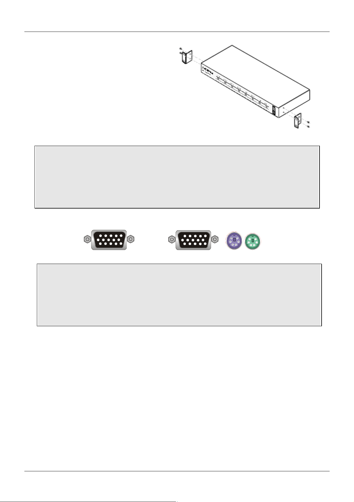
Step 1
Switch off all the computers to be attached.
Step 2 – Local Console
Connect the keyboard, monitor and mouse
directly to the sockets of the LINDY CPU
Switch labelled Console Port. If your
keyboard has a 5 Pin DIN connector you can
use a PS/2 adaptor (LINDY No. 70129).
Please note: Serial Mice with 9 Way D or
USB connectors are not supported and
cannot be used!
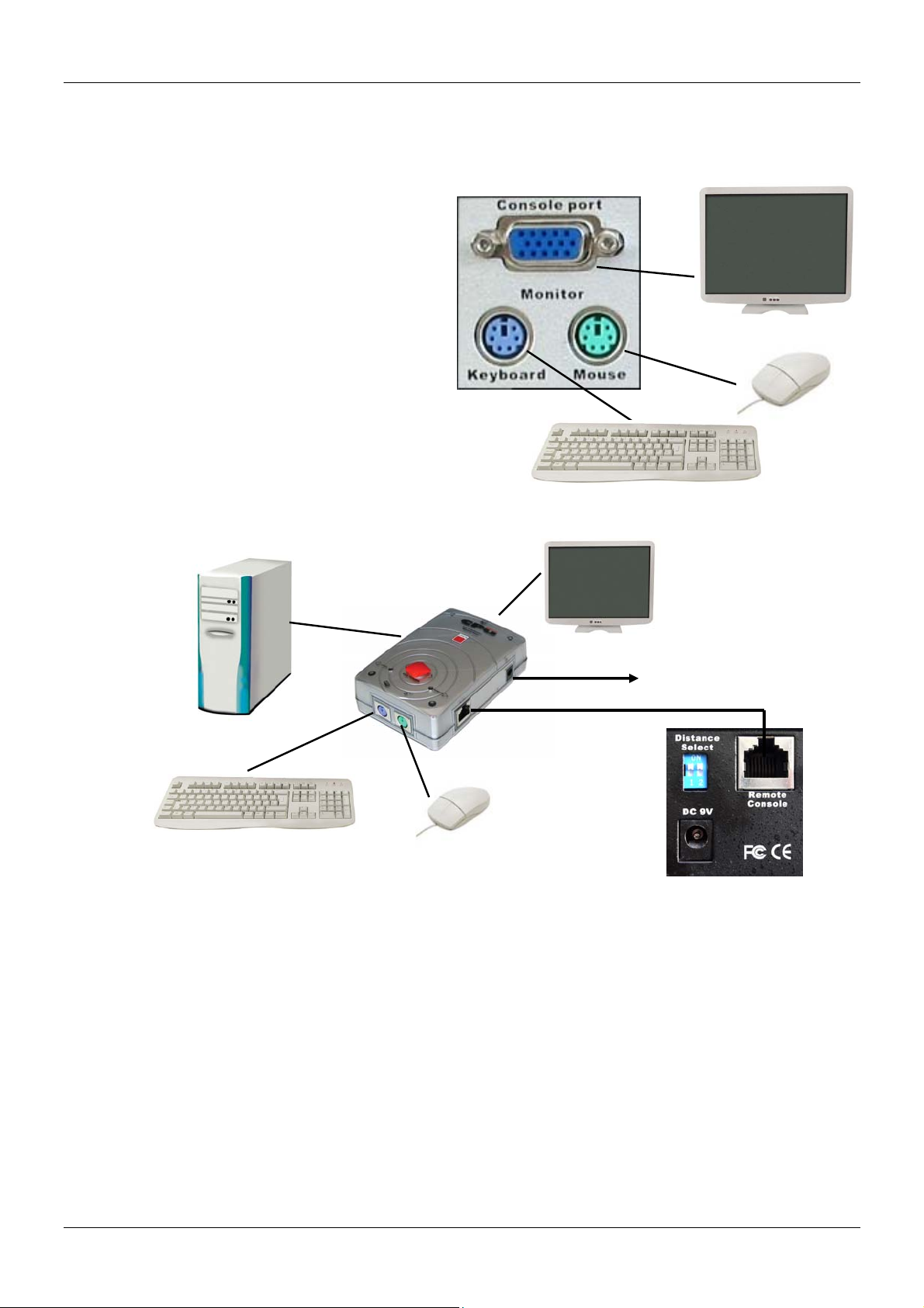
Step 3 – Remote Console (PXT only)
1. Use CAT5 or higher, straight through type network cable. The maximum connection
distance is 150m (500 feet)
2. Plug one end of the cable into the RJ-45 connector on the PXT switch. Plug the other
end of the cable into the RJ-45 port on the Remote Receiver module
3. Connect a monitor, keyboard and mouse to the relevant ports on the Remote
Receiver module
4. Connect a local workstation computer to the relevant ports on the Remote Receiver
module
5. Connect the power adapter to the socket on the Remote Receiver module
To Power
Adapter
5
Page 8
English Manual
6. When using CAT5/5e/6 cable over a distance greater than 90m
(300 feet), please set the DIP switches at the rear of the CPU
Switch to ON/ON. (Please note that video resolutions over
1280x1024 are not supported for distances greater than 90m)
Note: Both local and remote consoles have the same priority control of the switch and
the connected computers. Therefore, to prevent erratic operation please ensure that the
local and remote consoles are not used at the same time!
Step 4 – Computer connection
After the console ports are connected, connect the servers and PCs to the ports labelled 1…16.
Attach the power supply to the CPU Switch and plug the other end into a mains socket. You will
see the LED for Port 1 light up, and you will hear a beep. Switch on your monitor.
Note: Always plug in the power supply. Although the PCs connected to the CPU Switch
may be able to supply enough power to the unit, the power adapter is needed to daisy
chain more CPU Switches. If you do not plug in the power adapter unexpected and
erratic operation may occur.
Step 5 – VGA Tuning of the CAT5 Extender (PXT only)
Computer connection (image shows CPU Switch P8 model)
When using the Remote Console Receiver, optimum image quality can
be maintained by using the VGA Tuning adjustment control on top of the
unit.
6
Page 9
English Manual
)
g
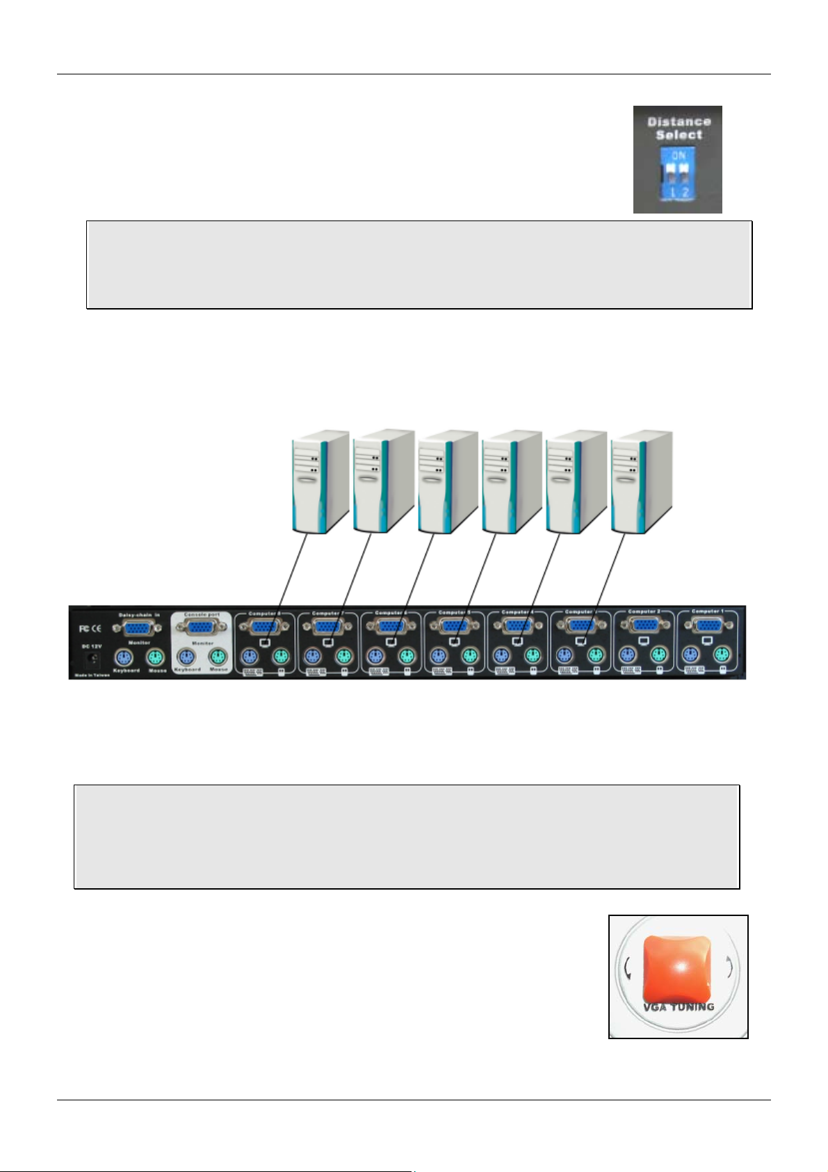
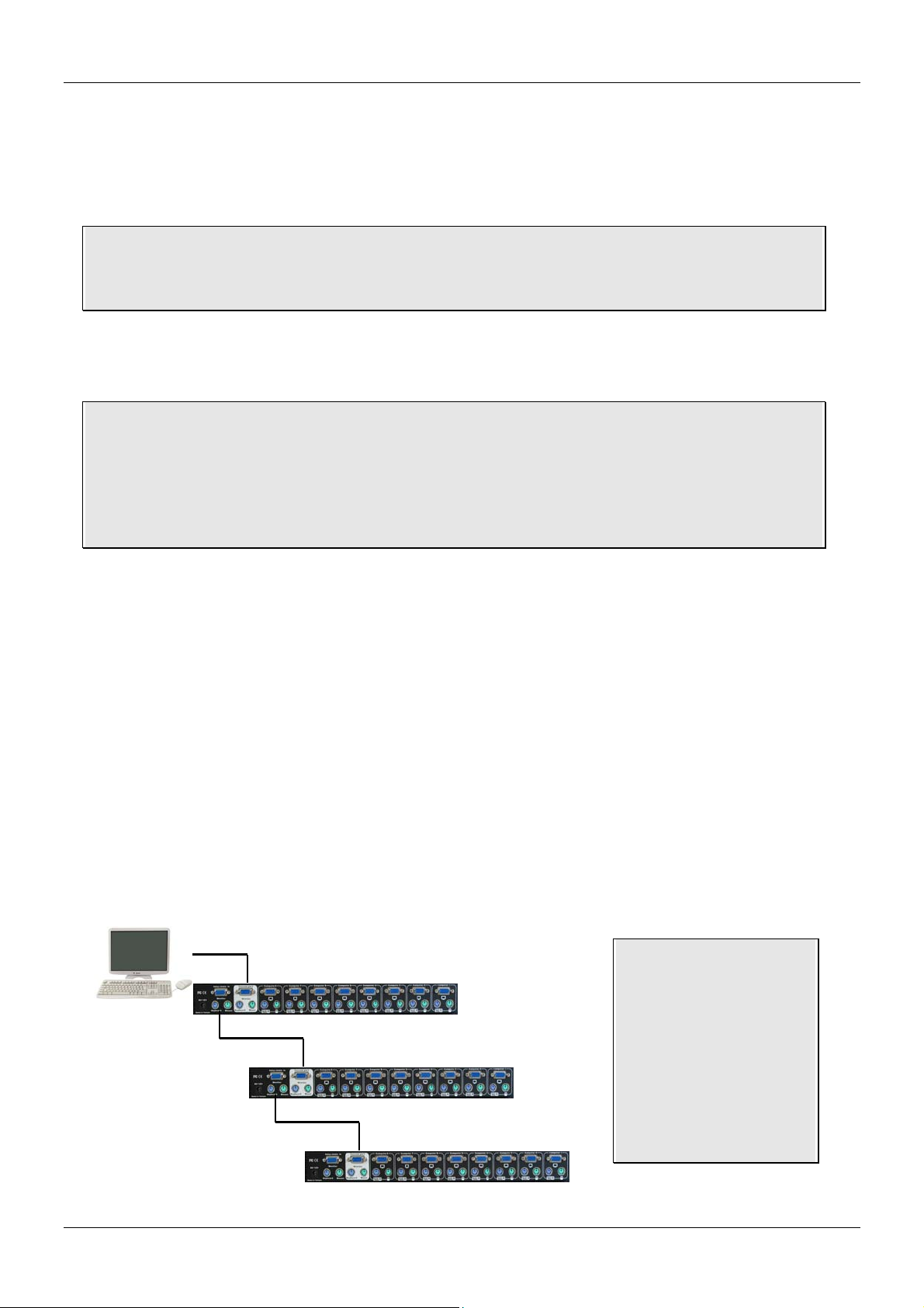
Cascading / Daisy Chaining of multiple CPU Switches
You can integrate up to 8 CPU Switches in one KVM daisy chained installation. Using the CPU
Switch P16 or P16XT, this gives a maximum of 128 attached computers.
Please note: If the daisy chain cable length over all CPU Switches exceeds 10m (30
feet) and picture quality deteriorates, a VGA amplifier such as the LINDY VGA Extender
(LINDY No. 32386) can be used.
To connect an additional CPU Switch to the MASTER (or previous) CPU Switch use a standard
(VGA + 2 x PS/2) 3-in-1 KVM cable, all connectors male.
Note: In a mixed P/PXT Series daisy chained/cascaded installation the MASTER CPU
Switch must be a PXT model.
If you would like to daisy chain 4, 8 port and 16 port CPU Switches together, the
MASTER CPU Switch must be a 16 port CPU Switch!
Step 1 - Connect the local console
Connect your keyboard, mouse and monitor to the console port (white coloured background) of
the MASTER CPU Switch.
Step 2
Use one end of a 3-in-1 KVM cable to connect the daisy chain port of the MASTER/previous
CPU Switch and the other end to the console port (white coloured background) of the next
SLAVE CPU Switch.
Step 3 - Cascading
Repeat the previous step to daisy chain more CPU Switches. Each individual switch in the chain
represents a different Bank. The MASTER switch is Bank 1 and each cascaded SLAVE follows
on as Bank 2, 3, 4 etc. to a maximum of eight banks/switches.
Note: If video quality
Bank 1 (Master
deteriorates you can
add a VGA amplifier
such as the LINDY
VGA Extender (No.
Bank 2
32386), between the
fifth and the sixth CPU
Switch to enhance the
Bank 3...to a maximum of 8
Cascadin
CPU Switches
VGA signal.
7
Page 10

English Manual
Step 4 – Resetting the Switches
After you have connected and switched on the SLAVE CPU switches and computers, all of the
CPU switches must be reset. First, reset the SLAVE CPU Switch at the end of the daisy chain
and then reset all of the other SLAVE switches up to the MASTER CPU switch.
To reset the switch, press and hold the Bank button and P4 or P8 button (depending on model)
on the front panel of the switch.
Each SLAVE switch should now show a dash in its BANK display.
Now, reset the MASTER switch - it will show a 1 in the BANK display. Each SLAVE switch
BANK display will now change to a number according to its position in the daisy chain.
8
Page 11

English Manual
Operation
Important note: Your monitor will only display one PC signal at any one time. All
keyboard and mouse commands are sent to this PC only. After initial power up, port 1 is
active by default.
When a PC is connected to the currently selected port and it is not switched on,
or is in sleep mode, the monitor will not display any signal.
Password Security
When you power on the CPU Switch it will ask you for a password. The default password is
eight zeros –“00000000”. Please key in eight zeros in the password field.
Note: Please don’t change the password until you are familiar with the operation of the OSD
menu – i.e. keep the default password “00000000”. Otherwise, if you forget the password, you
will need to send the CPU Switch back to LINDY for maintenance to clear the password.
Hot Plug Support
The CPU Switch supports a “Hot Plug” function for easy addition or removal of PCs. The user
can arrange or maintain the PCs as follows:
a. A PC can be disconnected and reconnected to the same or different port of the KVM switch
without having to power it off as long as it is currently not connected to the console.
b. The mouse driver of the PC has to support the hot plug function or the computer may need
to be rebooted when it is reconnected.
c. You can unplug your mouse or keyboard from the console port and plug it back in at any
time. You should not use different types of mice when doing this
d. A SLAVE CPU switch can be added or removed at any time, but after adding or removing a
switch you must reboot all of the CPU switches. You DO NOT need to reboot the computers.
Please note: Some Operating Systems such as certain Unix versions are unable to
support the “Hot Plug” function. If you Hot Plug when using this kind of O.S., it may cause
unpredictable operation or may shut down the PC. Before attempting to use the Hot Plug
feature, please make sure you’re O.S. and mouse software driver support the Hot Plug
feature.
Computer / Port Selection
You can select the computer you want to access in three different ways:
Front panel push button selection
Keyboard hotkey selection
On screen display menu selection
9
Page 12
English Manual
PXT-Series Remote Console Operation: When using the CAT5 Remote Extender unit you
can switch between computers using hotkey and OSD. To access the CPU Switch you must
switch to KVM console operation.
Scroll
+ + = Switches between local workstation access and CPU
Lock
Scroll
Lock
Switch remote console operation
C
Port LED Display
The front panel of the CPU Switch has two LEDs for each port.
When the LED labelled “P” is illuminated GREEN a computer attached to this port is powered
on. When the LED labelled “S” is illuminated RED, the KVM console is connected to this port. If
this LED flashes, the console is connected to this port but either no computer is attached, or the
attached computer is not switched on.
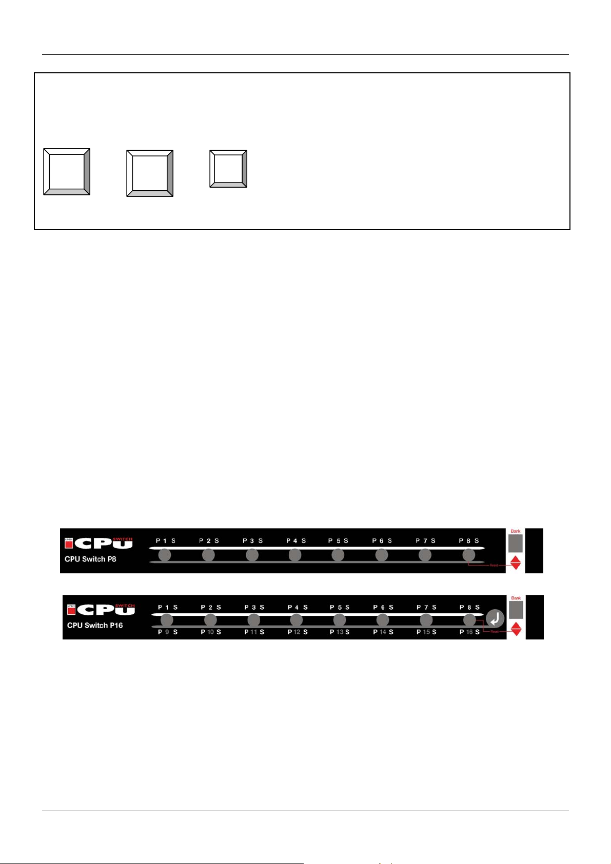
Front panel push button selection
You can select a computer by pressing the appropriate port push button. For the 4 and 8 port
models the buttons are centred in the grey circle below the port LEDs.
For the 16 port models, CPU Switch P16 and P16XT, each push button refers to two ports. To
access ports 9 to 16 you must push the button marked “↵” and the required port button
simultaneously.
Front panel of LINDY CPU Switch P8
Front panel of LINDY CPU Switch P16
For cascaded CPU Switches you can ONLY use the port selection push buttons on the
MASTER CPU Switch to switch the SLAVES (you can also switch via OSD or keyboard hotkey).
10
Page 13
English Manual
Keyboard Hotkey Selection
You can also conveniently select the computer to be accessed and displayed by switching ports
through simple keyboard key sequences. To send commands to the KVM switch, the “SCROLL
LOCK” key must be pressed twice within 2 seconds. You will hear a beep to confirm that the
keyboard is in hotkey mode. If you have not pressed any key in hotkey mode within 2 seconds,
the keyboard will return back to Operating System control status.
Direct Port Selection / Keyboard Hot Key Commands:
Within 2 seconds
+ + = Previous Port
Scroll
or
Lock
+ + = Next Port
Scroll
Lock
↑
↓
Tip: Hold the arrow key down,
or press multiple times, to cycle
through the ports
CPU Switch/Bank Selection:
The CPU Switch P-Series/PXT range supports cascading of up to 8 CPU Switches (Banks).
Therefore, when using direct hotkey port selection you must include the key sequence for the
CPU Switch/Bank:
Scroll
+ + +
Lock
Scroll
Lock
Bank
No 1~8
Port No.
01~04 (4 port)
01~08 (8 port)
01~16 (16 port)
Example: To access a computer attached to Port 6 of the first CPU Switch you should
press the following hotkeys:
Scroll
Lock
+ + + +
Scroll
Lock
1 0 6
To use hotkey switching to access another CPU Switch / Bank:
Scroll
+ + = Previous Bank
Lock
Scroll
Lock
Scroll
Lock
Scroll
+ + = Next Bank
Lock
Page
Up
(This will only work if a daisy
chained CPU Switch is present)
Page
Down
Important Note:
Always keep in
mind to include
leading zeros for
all ports below 10!
i.e.104 for Port 4 of
the first Switch.
Bank no. and
Port no. selection
must be made
using the
numeric keys on
the keyboard.
Keys on the
numeric keypad
are not available
as hot key
commands!
11
Page 14
English Manual
Auto Scan mode:
Scroll
Lock
Scroll
+ + = Auto Scan (Press any key to exit Auto Scan Mode)
Lock
S
Beeper Function (Enables and Disables beep during Auto Scan):
Scroll
+ + + = Beeper
Lock
PXT-Series Remote Console Operation:
When using the CAT5 Remote Extender unit you can switch between servers by hotkey and
OSD. To access the CPU Switch you must switch to KVM console operation.
Scroll
+ + = Switches between local workstation access and CPU
Lock
Scroll
Lock
Scroll
Lock
Switch remote console operation
B
C
12
Page 15
English Manual
On Screen Display Menu (OSD) port selection
The On Screen Display menu provides a lot of information about the CPU Switch and the
attached computers, and offers advanced administration features and full CPU Switch control to
the user.
PXT models only: From the Remote Console, the OSD is only available when you have
switched access to the CPU Switch!
To invoke the On Screen Display Menu press the following hotkeys:
Scroll
Lock
+ + = On Screen Display Menu
The OSD menu closes down automatically after a specified time period, which can be set in the
OSD settings menu. The time selected can be between 5 and 99 seconds
The OSD menu can be invoked even when the CPU Switch is currently switched to a port with
no connected or a non-powered on PC. In this case the resolution of OSD menu is fixed to a
1024 X 768 virtual frame.
If you wish to, you can restore the factory default values of the OSD. Please note this does not
include resetting the password! The bank LED display on the front panel will flash during the
memory refresh process.
Scroll
Lock
(Note: Not including password)
+ + = OSD setting back to factory default value
ROM REFLASH
When the OSD values have been reset back to factory default, the bank LED on the front panel
will stop flashing.
OSD also allows you to give each attached computer its own name. A name search function is
also available from the OSD:
Scroll
Lock
F I N D : █
+ + = Search the same PC name
Scroll
Lock
Scroll
Lock
Space Bar
R
An OSD overlay window will be displayed on the screen
during the memory refresh process
Scroll
Lock
(Note: Search PC name starting from 1
F
You can type in one character up to a complete name. The
upper part of the window will display all computer names
that match one by one. You can use the UP/DOWN cursor
keys to toggle through this name list.
Press ENTER to switch to the computer displayed in the
upper window.
ESC closes the window
st
PC port)
13
Page 16

English Manual
The OSD Menu displays the following screen for a 16 port CPU Switch. For a 4 port or 8 port
model you will find less ports listed respectively.
a. You can toggle between the 3 parts of the OSD menu (Bank PC names, CPU Switch
Settings) using the TAB key. The lower light blue part of the OSD lists keyboard controls.
BANK : 1
01 SYSTEM 01 02
03
05
SYSTEM 03 04
SYSTEM 05 06 SYSTEM 06
07 SYSTEM 07 08
SYSTEM 02 (
SYSTEM 04
SYSTEM 08
09 SYSTEM 09 10 SYSTEM 10
11
13 SYSTEM 13 14
OSD : 10 SEC. CHANGE PASSWORD
15
SYSTEM 11 12
SYSTEM 12
SYSTEM 14
SYSTEM 15 16 SYSTEM 16
SCAN: 10 SEC. CONSOLE ON/OFF
ESC : QUIT ENTER :COMPLETE
TAB : NEXT INSERT :EDIT
©/ª: SELECT PORT
PgDn/PgUp: BANK SELECT
f. Use the “PgUp” or “PgDn” key to switch to another daisy chained CPU Switch / Bank. This
function only works when another CPU Switch/Bank is connected.
01 SYSTEM 01 02
SYS█EM 02 (
OSD : 10 SEC. ( CHANGE PASSWORD
SCAN: 10 SEC. CONSOLE ON/OFF
The TAB key toggles between the fields. Simply overwrite the fields with your chosen values.
b. The 1
line bar is the bank or CPU Switch
number
c. The 2nd part (dark blue) is the
attached PC name list. You will find
the system number list from 01 to
04 (for 4 port version) or from 01 to
08 (for 8 port version) or from 01 to
16 (for 16 port version). You can
rename your PCs here (maximum 8
characters). The factory default PC
name is “SYSTEM 01”, “SYSTEM
02”, etc.
d. The sun symbol “☼” next to the
PC name indicates that the
attached computer is powered on.
e. You can use the CURSOR
keys (up arrow, down arrow, left
and right arrow) to select the port
you want to access and press the
ENTER key to switch.
g. To change the name of a
computer select the port and press
the “INS” key to edit the name.
Press the “Enter“ key to save it.
h. To access the third part of the
OSD containing OSD, SCAN,
CHANGE PASSWORD, CONSOLE
ON/OFF, etc. press the “TAB” key
st
part of the OSD window
14
Page 17

English Manual
i. OSD means that the OSD window is displayed on your monitor for 10 sec. You can modify
this value from 05 sec to 99 sec. Default is 10 sec.
j. SCAN displays the scan duration per channel in Auto Scan Mode. The default SCAN time
is 10 sec., the maximum scan time can be set to 99 sec, it cannot be less then 5 sec.
k. CONSOLE ON/OFF is used to prevent unauthorized use of the console. “CONSOLE ON”
means that any user can access the console. “CONSOLE OFF” (factory default) means that
any user will have to enter the password before getting access. When the password is entered
correctly the CONSOLE status will be set to ON. To lock the console again the status has to be
changed from CONSOLE ON to OFF via OSD. Also if the current CONSOLE state is ON and
you reset the KVM switch, the CONSOLE will be reset to the OFF state.
l. CHANGE PASSWORD is used
ENTER PASSWORD : █
ESC : QUIT ENTER :
ENTER NEW PASSWORD : █
ESC : QUIT ENTER :
RETYPE NEW PASSWORD : █
ESC : QUIT ENTER :
NEW PASSWORD COMPLETE
ESC : QUIT ENTER :
When you have switched to a certain port on the CPU Switch the keyboard and mouse
commands are directed to the attached computer and its monitor signal is displayed on the
screen.
In this overlay window from the OSD you will see some basic
102
to indicate that this computer is online and powered on; and the computer name.
You can close almost any overlay OSD window by simply pressing the ESCAPE key.
SYSTEM 02
information for the selected computer / port. The OSD shows
the port number; the status of the attached computer - “☼”,
to set a new password. The factory
default is 8 digits “00000000”.
To change the password you have
to input the old password and then
type in the new password twice, to
prevent mistyping. The maximum
password length is eight digits.
Make sure you do not forget the
password. Otherwise you will have
to send the KVM Switch to LINDY
for maintenance.
Finally you will see the confirmation
message that the new password is
set.
15
Page 18

English Manual
Troubleshooting
If none of the LED displays of the CPU Switch are illuminated please check that the power
adapter is connected and switched on at the mains. The polarity is centre positive and the
power adapter needs to be DC 12V, 1A (or minimum DC 9V, 1A).
PXT models only: From the Remote CAT5 console the OSD is only available when you
have switched access from the local workstation to the CPU Switch. For troubleshooting
the CAT5 Remote Console unit, please see the end of this section.
Before you check any further please make sure that all cables are well connected!
If the CPU Switch reacts to keyboard input from the SCROLL LOCK key with a beep signal but
you get no monitor picture displayed please check if the currently selected computer is in sleep
mode or powered down. You can try to wake up this computer by pressing the ESCAPE key
several times until the CPU Switch no longer beeps, and then pressing spacebar or RETURN
key to wake up the computer. The CPU Switch supports VGA power save modes and suspends
the monitor signal if the currently selected computer has switched off the VGA signal.
1. Please check if your problem can be solved by resetting the CPU switch, via the push
buttons on the front panel. For cascaded systems please follow the procedures mentioned
in the CASCADING section.
2. The Monitor picture is not sharp or shows shadows: The maximum recommended VGA
cable distance is 5 meters without ghosting and degradation. Make sure you have used
high quality video cables with coaxial cores. If the diameter of the cable is less then 6mm
then the cable may not be high enough quality.
3. The maximum recommended PS/2 cable distance is 5 metres. Normally, the cable length is
based on the electronic driver capacity of your motherboards PS/2 ports. If you need longer
PS/2 distances it may be necessary to use a PS/2 extender.
4. Don’t press any keys on the keyboard while the selected computer is booting up. Otherwise
it may cause a keyboard error, or the keyboard may not be detected at the PC side.
5. The computer boots up fine, but the keyboard doesn’t work:
a) Make sure the keyboard works when directly plugged into the computer.
b) Try a different keyboard, but use standard PS/2 keyboards (some keyboards with extra
multimedia keys may not be supported).
6. The Mouse is not detected during PC boot up:
a. Make sure the mouse works when directly plugged into the computer. You have to
install the appropriate mouse driver on all connected computers!
b. Make sure the mouse is a true PS/2 mouse. A combo mouse will work just as long as it
is set for PS/2 mode with the correct adapter. Try a different mouse.
c. Some advanced mice like radio frequency mice, 5 button mice and scroll wheel mice
use very uncommon proprietary signals. Although LINDY has carefully checked for the
highest compatibility, we cannot guarantee that the CPU Switch will work with all known
mice, especially those developed and produced after P-Series/PXT-Series Switch
production.
16
Page 19

English Manual
d. Avoid moving the mouse or pressing the mouse buttons when switching ports.
e. Avoid switching ports during the PC shut down process.
7. If you have forgotten the “password” please contact LINDY.
PXT models only:
If everything works fine using the local console access to the CPU Switch, but problems occur
when you try to access from the CAT5 Extender please check the following.
Please see the hotkey commands above to switch remote console access between local
workstation computer and the CPU Switch ( Scroll Lock + Scroll Lock + C)
Mouse or keyboard problems
Please note that you should use similar or identical mice on both the remote and local console.
Make sure the correct mouse driver is installed on any PCs/servers connected to the switch and
the local workstation computer. Special functions of RF wireless mice like ID recognition and
battery status are proprietary mouse protocols and therefore are not supported by the KVM
switch. In such cases you may have to use Microsoft standard mouse drivers that will support all
the functions of 3 button and scroll wheel mice. The same applies to keyboards with special
multimedia buttons and proprietary drivers.
Monitor and/or OSD is not displayed correctly on the remote console
Please note that you must have the Extender power supply and a local workstation computer
powered on and attached to the CAT5 Remote Console unit. Otherwise the OSD and/or graphic
signal may not be displayed correctly on the remote console.
Please also note the maximum resolution versus distance over the CAT5 extension:
Up to 1600x1200 for distances up to 50m
Up to 1024x768 for distances up to 100m
Up to 800x600 for distances up to 150m
These are approximate values which depend on the quality and capability of your graphics
cards and monitors.
17
Page 20

Deutsches Handbuch
Überblick
Herzlichen Dank dass Sie sich für einen KVM-Switch aus der LINDY P/P-XT-Serie entschieden
haben . Bitte lesen Sie dieses Handbuch sorgfältig um alle Möglichkeiten zu erfassen, die Ihnen
dieser KVM-Switch bietet.
Über dies Handbuch – Dies Handbuch beschreibt die LINDY CPU Switch P-Serie
und die Dual Console P-XT-Serie. Diese KVM-Switches stimmen in den meisten
Funktionen überein. Wo sie sich unterscheiden wird klar darauf hingewiesen.
Durch den Einsatz der LINDY CPU Switches können Sie in erheblichem Maße Kosten
einsparen, z.B. für zusätzliche Monitore, Tastaturen und Mäuse und Sie sparen erheblich an
Platz und Ressourcenverbrauch für elektrische Leistung sowie Kühlleistung ihrer Air Condition
im Sommer. Ferner gibt es nie wieder Probleme durch das Verwechseln von Mäusen und
Tastaturen. Der Systemadministrator hat Zugriff auf alle angeschlossenen Rechner von einer
zentralen Konsole, bei den P-XT Modellen zusätzlich von einer weiteren Konsole z.B. im Büro.
LINDY CPU Switches der P-Serie erlauben den Zugriff auf bis zu 16 direkt angeschlossene
Rechner von einem einzigen Eingabeplatz mit Monitor, Maus und Tastatur.
LINDY CPU Switches der P-XT-Serie stellen einen zweiten Eingabeplatz zur Verfügung. Er
kann über den integrierten Cat.5 KVM Extender in einer Entfernung bis zu 150m an den
Büroarbeitsplatz des Systemadministrators abgesetzt werden. Dort bietet die Cat.5 Extenderbox die Möglichkeit zwischen Zugriff auf den Büro-Arbeitsplatzrechner und den CPU Switch und
damit alle angeschlossenen Server hin und her zu schalten.
Zum Anschluss von mehr als 16 Rechnern können die LINDY CPU P/P-XT Switches auf
einfachste Weise in einem Daisy Chain Bus kaskadiert werden. Bis zu 8 CPU Switches können
in einem Bus mit maximal 128 Servern zusammen gefasst werden. Dabei gehen keine Ports
durch Kaskadierung verloren.
Die CPU Switches der P/P-XT-Serie unterstützen das Umschalten zwischen den
angeschlossenen Rechnern auf 3 Arten: Auswahl über die Tasten an der Frontblende des CPU
Switch, Auswahl über Bildschirmmenü (OSD, On Screen Display), Auswahl über Tastaturhotkey. Die Tastatur- und Mausverbindungen werden vom CPU Switch permanent für alle
angeschlossenen Rechner emuliert, so dass keine Fehlermeldungen von den angeschlossenen
Rechnern erzeugt werden.
Bitte beachten - Da der CPU Switch die Maus- und Tastatursignale interpretieren,
emulieren und weiterleiten muss, ist es erforderlich, dass er die Protokolle “versteht”.
Die CPU Switches der P/P-XT-Serie unterstützen PS/2-Mäuse mit bis zu 5 Tasten und
2 Scrollrädern. Einige erweiterte Funktionen von kabellosen (Funk-)Mäusen und –
Tastaturen, die proprietäre nicht voll Microsoft® kompatible Treiber verwenden werden
möglicherweise nicht unterstützt.
18
Page 21

Deutsches Handbuch
Eigenschaften
4/8/16 Port KVM-Switch im kompakten 19” Rackmount-Gehäuse mit nur einer Höheneinheit
Zentraler Zugriff von einen Arbeitsplatz - Single console operation (P-Serie)
Zentraler Zugriff von zwei Arbeitsplätzen - Dual console operation – mit integriertem KVM
Cat.5 Extender (nur P-XT-Serie)
Inklusive KVM Cat.5 Extender mit Local und Remote Switch (nur P-XT-Serie)
Unterstützung für LINDY Mäuse und alle weit verbreiteten Mäuse mit bis zu 5 Tasten und bis
zu 2 Scrollrädern mit voll Microsoft-kompatiblen Treibern. Einige erweiterte Funktionen von
kabellosen (Funk-)Mäusen und –Tastaturen, die proprietäre nicht voll Microsoft® kompatible
Treiber verwenden, werden möglicherweise nicht unterstützt.
Unterstützt alle weit verbreiteten Betriebssysteme
Unterstützt auch Anschluss von USB Rechnern wie iMac, Power Mac and Sun
Microsystems (zusätzliche PS/2-USB Adapter, z.B. LINDY Nr. 42866 werden benötigt)
Hot Plug Support – Anschließen und Entfernen von Rechnern im laufenden Betrieb
Höchste Videoqualität – Unterstützt Bildschirmauflösungen bis 1920x1440 für die lokale
Konsole
Unterstützt Bildschirmauflösungen bis 1600x1200 via Cat.5 KVM Extender bis zu einer
Entfernung von 50m. Für größere Distanzen sinkt die unterstützte Auflösung kontinuierlich,
z.B. bis auf 800x600 @ 150m
Benötigt keine Softwareinstallation - Auswahl der Rechner via Tastatur-Hotkey, OSD oder
Tasten am CPU Switch
Passwortschutz mit bis zu 8 Zeichen
Namensvergabe für die angeschlossenen Rechner – Suchfunktion nach Name
Auto-Scan-Modus um die angeschlossenen Rechner durchzuscannen, Zeit einstellbar
Permanente Tastatur- und Mausemulation
Tastaturstatus (Num-Lock, Shift-Lock, etc.) wird korrekt pro Port gespeichert und zurück
geladen
LED Displays zur überschaubaren Anzeige des Status der angeschlossenen Rechner
Signalton zur Bestätigung von Hotkey-Eingaben und Schaltvorgängen
Die 4 und 8 Port Modelle der P-Serie verwenden Standardkabel zum Anschluss der
Rechner. Zur besseren Übersichtlichkeit empfehlen wir die Verwendung von 3-in-1 KVMKabeln!
LINDY CPU Switch P16 und alle Modelle der P-XT Serie verwenden Platz sparende
Systemkabel zum Anschluss der Rechner und ermöglichen so die Konzentration von 16
Anschlüssen in nur einer Höheneinheit.
Daisy-Chain-Kaskadierung: kein Verlust von Serverports bei Kaskadierung
19
Page 22

Deutsches Handbuch
Lieferumfang
CPU Switches der P-Serie
LINDY CPU Switch P4, P8 oder P16
Netzteil
19” Einbaukit (Winkel und Schrauben)
Dies Handbuch
PXT-Series Switches
LINDY CPU Switch P4XT, P8XT or P16XT
Cat.5 KVM Extender Remote Console Switch
1x 3-in-1 KVM-Kabel zum Anschluss des Bürorechners an den Cat.5 KVM Extender Remote
Console Switch
Zwei Netzteile (1 x CPU Switch, 1 x Cat.5 KVM Extender Remote Console Switch)
19” Einbaukit (Winkel und Schrauben)
Dies Handbuch
Optionale Anschlusskabel und Zubehör (nicht enthalten)
Kombi (3-in-1) KVM Kabel (für P4/P8, P-XT Extender Box, Daisy Chain Kabel)
o 1m LINDY Art.Nr. 33711
o 2m LINDY Art.Nr. 33712
o 3m LINDY Art.Nr. 33713
o 5m LINDY Art.Nr. 33714
Kombi-KVM-Systemkabel (für P16 und alle Modelle der P-XT-Serie)
o 2m LINDY Art.Nr. 32506
o 3m LINDY Art.Nr. 32507
o 5m LINDY Art.Nr. 23508
AT Tastaturadapter DIN-6 an PS/2 LINDY Art.Nr. 70129
PS/2 -> USB Konverterkabel LINDY Art.Nr. 42866
LINDY VGA Extender LINDY Art.Nr. 32386
20
Page 23

Deutsches Handbuch
Installation
Bevor Sie mit dem Aufbau beginnen, prüfen
Sie bitte ob alle Teile enthalten sind. Siehe
hierzu die vorstehende Liste Lieferumfang.
Falls Sie den LINDY CPU Switch in einem
19“ Rack einbauen wollen befestigen Sie
bitte die 19“ Montagewinkel mit den
beiliegenden Schrauben.
P-Serie - Neben den anzuschließenden Rechnern benötigen Sie lediglich einmal
Monitor, Maus und Tastatur sowie die notwendigen Anschlusskabel mit
Standardanschlüssen.
Bitte beachten: Für den CPU Switch P16 und alle Modelle der P-XT-Serie werden
besondere Systemkabel zum Anschluss der Server benötigt. Erst dies ermöglicht alle
Anschlüsse in nur einer Höheneinheit 19“ unterzubringen.
15poliger HD Stecker an 15poligen HD VGA Stecker und 2x 6poligen Mini-DIN Stecker
→
P-XT Modelle – Sie haben die Möglichkeit des Anschlusses einer weiteren Konsole via
Cat.5 KVM Extender. Am abgesetzten Büroarbeitsplatz muss ein lokaler
Arbeitsplatzrechner sowie ein Netzteil an die Extenderbox angeschlossen werden.
Bitte beachten: Für den CPU Switch P16 und alle Modelle der P-XT-Serie werden
besondere Systemkabel (s. o.) zum Anschluss der Server benötigt.
Falls Kabel zu kurz sind, empfehlen wir die Verwendung von längeren Kabeln. Es können aber
auch Verlängerungen eingesetzt werden (für die Systemkabel der P-XT Serie und den P16
jedoch nur auf der Serverseite, NICHT auf der Seite am KVM Switch!) Dabei ist jedoch zu
beachten, dass mehrere Stecker/Kupplung-Verbindungen immer die Signalqualität reduzieren
und die mögliche Gesamtlänge reduzieren. Besonders bei hohen VGA Auflösung ist davon
abzuraten.
21
Page 24

Deutsches Handbuch
Schritt 1
Schalten Sie alle Geräte aus.
Schritt 2 – Lokale Konsole (am CPU
Switch)
Verbinden Sie Tastatur, Maus und Monitor
mit dem CPU Switch an den Ports mit der
Bezeichnung Console port. Falls Ihre
Tastatur einen 5poligen DIN Stecker hat
benötigen Sie eine neuere Tastatur oder
einen PS/2-Adapter, z.B. LINDY Art. Nr.
70129.
Der Anschluss von USB-Mäusen oder von
seriellen Mäusen mit 9polgem D-Anschluss
wird NICHT unterstützt !
Schritt 3 – Cat.5 KVM Extender Box (nur P-XT Modelle)
Zum Netzteil
1. Verwenden Sie zur Verbindung von CPU Switch und Cat.5 KVM Extenderbox
Netzwerk Patchkabel Cat.5 oder höher, 1:1 verbunden. Die maximale Kabellänge
beträgt ca. 150m bei Auflösungen bis 800x800. Für höhere Auflösungen gelten
kürzere Distanzen.
2. Schließen Sie das Netzwerkkabel an den beiden RJ-45 Buchen an.
3. Schließen Sie Monitor, Maus und Tastatur an den entsprechend gekennzeichneten
Buchsen des Cat.5 Extenderbox an.
4. Schließen Sie den Büro-Arbeitsplatzrechner and die entsprechend gekennzeichneten
Buchsen der Cat.5 Extenderbox an.
5. Schließen Sie das Netzteil an die Cat.5 Extenderbox an.
22
Page 25

Deutsches Handbuch
6. Bei Verwendung von Netzwerkkabel mit einer Länge über 90m
setzen Sie bitte beide DIP-Schalter am CPU Switch auf ON/ON.
Beachten Sie bitte, dass Auflösungen über 1280x1024 für
Distanzen über 90m nicht unterstützt werden
HINWEIS: Beide Konsolen, Local und Remote, haben die gleiche Priorität beim Zugriff
auf den KVM Switch und damit auf die angeschlossenen Server. Sie zeigen immer den
gleichen Server. Um Fehlbedienung zu verhindern stellen Sie bitte sicher, dass nicht
beide Konsole zur gleichen Zeit benutzt werden.
Schritt 4 – Anschluss der Server
Schließen Sie als nächstes die Rechner and die Ports 1…16 des CPU Switch an.
Schließen Sie das Netzteil an die Versorgungsspannung und an den CPU Switch an.
ACHTUNG: Schließen Sie immer das Netzteil an. Obwohl die angeschlossenen
Rechner den CPU Switch auch über die PS/2 Anschlüsse mit Strom versorgen können,
wird das Netzteil zur korrekten Funktion beim Aufbau von kaskadierten Systemen
benötigt! Überprüfen Sie bei unregelmäßigen Fehlermustern das Netzteil auf Funktion.
Schritt 5 – VGA Tuning des Cat.5 Extender (nur P-XT Modelle)
Anschluss der Rechner (Bild zeigt CPU Switch P8 Rückseite)
Sie können die Bildqualität durch Einstellung des VGA Tuning Reglers in
gewissen Grenzen anpassen. Versuchen Sie die optimale Einstellung zu
finden, ändern Sie bei unbefriedigendem Ergebnis auch die Einstellung
der beiden DIP Switches am CPU Switch.
23
Page 26

Deutsches Handbuch
)
g
Daisy Chain Kaskadierung mehrerer CPU Switches
Bis zu 8 CPU Switches können in einer KVM Daisy Chain Installation integriert werden. Bei
Verwendung von CPU Switch P16 oder P16XT ergibt dies maximal 128 Server.
Bitte beachten Sie, dass bei Überschreitung einer Daisy-Chain-Buslänge über alle
Switches von 8m eventuell ein VGA-Extender ( LINDY Art.Nr. 32386) eingesetzt
werden muss.
Um jeweils einen weiteren Slave CPU Switch am übergeordneten CPU Switch anzuschließen
wird ein 3-in-1 KVM-Kabel mit Standardanschlüssen verwendet, alle Anschlüsse als Stecker.
HINWEIS: In einer gemischten kaskadierten Umgebung P / P-XT Modelle muss nur der
MASTER CPU Switch ein P-XT Modell sein.
Wenn Sie 4, 8 und 16 Port CPU Switches gemischt einsetzen wollen, muss der
MASTER CPU Switch ein 16 Port CPU Switch sein!
Schritt 1 – - Kaskadierung - Anschluss der lokalen Konsole
Verbinden Sie Tastatur, Maus und Monitor mit dem MASTER CPU Switch an den Ports mit der
Bezeichnung Console port (weißer Hintergrund) .
Schritt 2 - Kaskadierung
Verbinden Sie die mit CONSOLE benannten Monitor-, Maus- und Tastaturports des Slave-
Switches mit den entsprechenden DAISY CHAIN bezeichneten Ports des übergeordneten CPU
Switch. Verwenden Sie möglichst kurze Kabel.
Schritt 3 - Kaskadierung
Wiederholen Sie den vorhergehenden Schritt um weitere CPU Switches anzuschließen. Jeder
einzelne CPU Switch repräsentiert eine Bank. Der MASTER Switch ist Bank 1 und die weiteren
kaskadierten SLAVE folgen als Bank 2, 3, 4 etc. bis zum Maximum von 8 Banks/Switches.
Bitte beachten Sie, dass
Bank 1 (Master
bei Überschreitung einer
Daisy-Chain-Buslänge
über alle Switches von
8m eventuell nach ca. 8m
Bank 2
Gesamtkabellänge ein
VGA-Extender ( LINDY
Art.Nr. 32386) eingesetzt
Bank 3...to a maximum of 8
Kaskadierun
von CPU Switches
werden muss.
24
Page 27

Deutsches Handbuch
Schritt 4 – Resetten der Switches
Nach Anschluss, Einschalten und Booten aller Switches und Rechner müssen alle CPU
Switches RESETTET werden, und zwar zuerst der entfernteste SLAVE CPU Switch und zum
Schluss der MASTER CPU Switch.
Die Slaves sollten jeweils nach dem eigenen Reset einen Strich im Bank Display anzeigen.
Zuletzt wird der Master resettet. Danach zeigt der Master eine 1 und die Slaves in Ihrer
Reihenfolge die entsprechende Ziffer an.
25
Page 28

Deutsches Handbuch
Betrieb
Wichtiger Hinweis: Ihr Monitor zeigt immer nur ein Videosignal, das des gerade
gewählten Ports. Alle Tastatur- und Mauskommandos werden nur an den Rechner
gesendet, der gerade ausgewählt ist.
Falls ein PC nicht eingeschaltet ist oder sich in einem Energiesparmodus (Sleep Mode)
befindet, wird der Monitor kein Signal anzeigen!
Bitte beachten Sie, dass dies NICHT ein Zeichen für einen Defekt am CPU Switch ist.
Passwortschutz
Wenn Sie Ihren CPU Switch einschalten fragt er das Passwort ab. Das Default Passwort sind
acht Nullen – 00000000. Bitte geben Sie diese acht Nullen auf Aufforderung hin ein.
Bitte beachten: Ändern Sie das Passwort NICHT bevor Sie nicht vertraut sind mit dem Switch
und der Bedienung des OSD Menüs. Notieren Sie sich neue Passworte an einem sicheren Ort!
Falls Sie das Passwort vergessen, ist es unumgänglich, den Switch zur Löschung des
unbekannten Passwortes an LINDY einzusenden !!!
Hot Plug Support
Der CPU Switch unterstützt die Hot Plug Funktion zum einfachen Einbinden oder Herausnehmen von Rechnern aus dem System unter folgenden Bedingungen:
1. Ein Rechner kann ohne erneutes Booten aus dem System herausgenommen und am
gleichen oder einem anderen Port wieder angeschlossen werden unter der Voraussetzung, dass er gerade NICHT ausgewählt und mit der Konsole verbunden war.
2. Der Maustreiber des Rechners unterstützt Hot Plug.
3. Monitor, Maus und Tastatur können jederzeit abgezogen bzw. angeschlossen werden.
4. Ein SLAVE CPU Switch kann im laufenden Betrieb hinzugefügt oder entfernt werden.
Dies erfordert lediglich den Reboot aller CPU Switches, nicht aber der Rechner (siehe
Absatz über Kaskadierung).
ACHTUNG : Einige Betriebssysteme wie z.B. einige Unix unterstützen Hot Plug NICHT. Wenn
Sie unter diesen Betriebssystemen versuchen die Hot Plug Funktionalität zu verwenden kann dies
zu fehlerhafter Funktion oder sogar Herunterfahren des Rechners kommen. Bevor Sie die Hot
Plug Funktionalität verwenden, stellen Sie bitte sicher, dass das Betriebssystem dies unterstützt.
Auswahl des aktiven Computer / Port Auswahl
Die Auswahl des aktiven und angezeigten Rechner kann auf 3 verschiedene Arten erfolgen:
o Per Taster an der Front des CPU Switch
o Über Tastaur-Hotkey-Eingabe
o Über On-Screen-Display Menü Auswahl
26
Page 29

Deutsches Handbuch
P-XT-Modelle: Bedienung via Cat.5 Extenderbox: Von der an die Cat.5 Extenderbox
angeschlossenen Konsole schalten Sie zwischen Zugriff auf den lokalen Arbeitsplatzrechner
und Zugriff auf den CPU Switch und damit das OSD mit untenstehendem Hotkey um.
Rollen
+ + = Schaltet Zugriff zwischen lokalem Arbeitsplatzrechner und
Zugriff auf den CPU Switch und damit das OSD um
Rollen
C
Bedeutung der Frontanzeigen, LEDs
Der LINDY CPU Switch hat für jeden Port zwei Anzeige-LEDs
Falls die rote LED “P” Rot leuchtet, ist an diesem Port ein Computer angeschlossen und eingeschaltet. Falls diese LED blinkt, ist entweder kein Rechner angeschlossen oder er ist nicht eingeschaltet, aber dieser Port ist gerade ausgewählt und aktiv und mit der Konsole verbunden.
Falls die grüne LED “S” GRÜN leuchtet ist dieser Port des CPU Switch gerade ausgewählt,
aktiv und mit der Konsole verbunden.
Umschalten über die Schalttasten an der Frontplatte
Über die runden grauen Schaltfelder an der Front des CPU Switch kann ein Port per Tastendruck direkt ausgewählt werden.
Beim 16 Port Modell muss für die Ports 9-16 zusätzlich die “↵”-Taste gedrückt werden.
Frontblende des LINDY CPU Switch P8
Frontblende des LINDY CPU Switch P16
Bei kaskadierten Systemen können auch die SLAVES grundsätzlich AUSSCHLIESSLICH über
die Tasten am MASTER geschaltet werden (oder über Hotkey und OSD).
27
Page 30

Deutsches Handbuch
Direkte Port-Anwahl / Tastatur HotKey Kommandos:
Sie können bequem von der Tastatur aus die Ports bzw. Rechner anwählen. Dazu drücken Sie
zweimal kurz hintereinander die ROLLEN-Taste. Zur Bestätigung sendet der CPU Switch einen
Signalton und versetzt die Tastatur kurzzeitig (ca. 2 Sekunden) in den Kommandomodus.
Weitere Tasteneingaben müssen daher immer kurzfristig erfolgen.
innerhalb 2 Sekunden
+ + = Nächster Port
Rollen Rollen
↑
oder
+ + = Vorheriger Port
↓
Achtung: Festhalten oder
mehrfaches Drücken der
Cursortasten schaltet weiter
CPU Switch P4 / P8 / P16 unterstützt die Kaskadierung von bis zu 8 CPU Switches
(Banks). Daher muss eine direkte Eingabe der Portnummer immer auch die Switch/BankNummer enthalten:
Rollen Rollen Bank
+ + +
Nr: 1~8
Port Nr.
01~04 (4 Port)
01~08 (8 Port)
01~16 (16 Port)
Beispiel: Um auf den Port 6 des (ersten) CPU Switch zu schalten geben
Sie folgendes Tastatur-Hotkey-Kommando ein:
ROLLEN + ROLLEN + 1 + 0 + 6
Um zum gleichen Port eins kaskadierten CPU Switch zu schalten:
Rollen Rollen
+ + + = Vorherige Bank
Rollen Rollen
+ + + = Nächste Bank
Bild ↑
Funktioniert nur in
kaskadierten Systemen
Bild ↓
Signalton:
Wichtige
Anmerkung:
Sie müssen für
Ports unter 10
führende Nullen
immer mit eingeben!
Also 104 für Port 4
am ersten Switch!
Bank- und PortNummer MÜSSEN
über die Zifferntasten oberhalb der
Buchstaben eingegeben werden!!
Die Tasten des
numerischen Feldes
können NICHT
verwendet werden !!
+ + + = Signalton (Kontrolle)
Rollen Rollen
AutoScan-Modus:
B
Rollen Rollen
+ + = AutoScan
Um den AutoScan-Modus zu verlassen drücken
Sie eine beliebige oder die Leertaste.
Der CPU Switch stellt einige weitere Hotkey-Kommandos zur Verfügung. Näheres dazu auf den
Folgeseiten.
S
28
Page 31

Deutsches Handbuch
Portauswahl über das On-Screen-Display Menue ( OSD )
P-XT-Modelle: Bedienung via Cat.5 Extenderbox: Von der an die Cat.5 Extenderbox
angeschlossenen Konsole schalten Sie zwischen Zugriff auf den lokalen Arbeitsplatzrechner
und Zugriff auf den CPU Switch und damit das OSD mit folgendem Hotkey um.
Rollen
+ + = Schaltet Zugriff zwischen lokalem Arbeitsplatzrechner und
Zugriff auf den CPU Switch und damit das OSD um
P-XT Modelle: von der an die Cat.5 Extenderbox angeschlossenen Remote Console ist
das OSD und Hotkey-Switching nur verfügbar wenn Sie den Zugriff auf den KVM-Switch
umgeschaltet haben!
Das OSD stellt umfangreiche Informationen über den Switch und die angeschlossenen Rechner
sowie Konfigurationsmöglichkeiten zur Verfügung.
Um das OSD aufzurufen wird folgender Hotkey eingegeben:
Rollen
Das OSD schließt sich automatisch nach einer kurzen einstellbaren Zeitspanne (5-99 Sek.).
Das OSD kann auch aufgerufen werden wenn der Switch auf nicht aktiven Ports steht.
Falls Sie jemals schwerwiegende Probleme mit den OSD Funktionen haben, können Sie alle
veränderten Werte (außer dem Passwort) auf die Default-Werte zurücksetzen. Während dieses
Vorgangs blinkt die BANK Anzeige des Switch.
Rollen
(Anmerkung: Außer dem Passwort!)
ROM REFLASH
Nach Abschluss dieses Prozesses wird die Anzeige gelöscht und die Bank Anzeige hört auf zu
blinken. Verwenden Sie diese Funktion nur im Notfall.
Das OSD ermöglicht es, jedem Rechner einen Namen zu geben. Und es stellt eine Namenssuchfunktion zur Verfügung. Bei großen Systemen kann dies sehr hilfreich sein.
Rollen
F I N D : █
Rollen
+ + = On Screen Display Menu
+ + = OSD setting back to factory default value
Rollen
Rollen
C
Leertaste
R
Während dieses Prozesses wird ein OSD Overlay Fenster auf
dem Monitor angezeigt.
Rollen
+ + = Suche nach einem Namen ….
(Suche startet am ersten Port)
F
Es kann von einem Buchstaben bis zum kompletten Namen
alles eingegeben werden, das OSD blendet alle gefundenen
Ports/Namen der Reihe nach ein. Mit den Cursortasten wird
durch die Suchergebnisse geblättert. RETURN wählt aus,
ESC schließt das Fenster ohne Aktion.
29
Page 32

Deutsches Handbuch
Das OSD Menü klappt in der unten abgebildeten Form auf dem Monitor auf. Bei Verwendung
eines 4 oder 8 Port CPU Switch P4 oder P8 finden sich entsprechend weniger Servereinträge
im OSD.
Zwischen 3 unterschiedlichen Breichen des OSD (1. Bank, 2. Rechnernamen, 3. SwitchEinstellungen) kann durch Drücken der Tabulator-Taste hin und her gewechselt werden.
BANK : 1
01 SYSTEM 01 02
03
05
SYSTEM 03 04
SYSTEM 05 06 SYSTEM 06
07 SYSTEM 07 08
09 SYSTEM 09
11
SYSTEM 11 12
10
13 SYSTEM 13 14
15
SYSTEM 15 16 SYSTEM 16
SYSTEM 02 (
SYSTEM 04
SYSTEM 08
SYSTEM 10
SYSTEM 12
SYSTEM 14
OSD : 1 0 SEC. CHANGE PASSWORD
SCAN: 1 0 SEC. CONSOLE ON/OFF
ESC : QUIT ENTER :COMPLETE
TAB : NEXT INSERT :EDIT
©/ª: SELECT PORT
PgDn/PgUp: BANK SELECT
d. Sie können die “ PgUp / Bild ↑ “ oder “ PgDn / Bild ↓” Tasten verwenden um zu einem
anderen CPU Switch bzw. auf eine andere Bank zu schalten, sofern angeschlossen.
e. Um den Namen eines Rechner zu ändern, selektieren Sie den Eintrag und drücken Sie die
EINFÜGEN-(Einf)-Taste um in den Editiermodus zu gelangen. Geben Sie den Namen ein
und betätigen Sie durch Drücken der ENTER-Taste.
01 SYSTEM 01 02
Sie können jedes OSD Fenster durch Drücken der ESCAPE Taste verlassen.
SYS█EM 02 (
a. Der erste Teil des OSD zeigt
die Switch/Bank-Nummer an
b. Der zweite Teil des OSD
zeigt die Rechnernamen an.
Sie finden die Rechner 1 bis 4 bei
CPU Switch P4/P4XT, die
Rechner 1-8 beim CPU Switch
P8/XT und die Rechner 1 bis 16
beim CPU Switch P16/XT.
Sie können den Rechnern Namen
mit maximal 8 Zeichen geben,
Defaulteinstellung ist SYSTEM 01
usw.
Das Sonnensymbol “ ☼ “ neben
dem Rechnernamen zeigt an,
dass der angeschlossene
Rechner eingeschaltet ist.
c. Sie können die Cursortasten verwenden um den
Rechnerport anzuwählen.
Drücken Sie die Enter-Taste zum
Umschalten.
30
Page 33

Deutsches Handbuch
f. Der dritte Teil des OSD mit
OSD : 1 0 SEC. ( CHANGE PASSWORD
SCAN: 1 0 SEC. CONSOLE ON/OFF
Das Handsymbol zeigt das aktuell gewählte Feld, Drücken der TAB-Taste wechselt
zwischen den Feldern, neue Werte überschreiben alte bei Eingabe.
g. “ OSD: 10 SEC ” zeigt die Zeit, nach der sich das OSD automatisch wieder ausblendet
sobald keine Taste mehr gedrückt wird. Default ist 10 Sek., Werte von 5 bis 99 Sekunden
können eingegeben werden.
h. “ SCAN: 10 SEC “ zeigt die Zeit an, die der Switch im AutoScan-Modus jeden Kanal
anzeigt. Default ist 10 Sek., es können Werte von 5 bis 99 Sekunden eingestellt werden.
i. “ CONSOLE ON/OFF “ wird verwendet, um den Passwort-Schutz / User-Zugriffsschutz auf
den Switch und die Rechner umzuschalten. CONSOLE ON steht für unbeschränkten
Zugriff / Passwortschutz abgeschaltet. CONSOLE OFF (Default) bedeutet, dass ein
Passwort eingegeben werden muss um wieder zugreifen zu können. Nach Eingabe des
korrekten Passwortes schaltet der Status auf CONSOLE ON. Um den Zugriffsschutz
wieder zu aktivieren muss der Status im OSD auf CONSOLE OFF gesetzt werden. Ein
RESET des CPU Switch schaltet ebenfalls auf CONSOLE OFF !
ENTER PASSWORD : █
ESC : QUIT ENTER :
ENTER NEW PASSWORD : █
ESC : QUIT ENTER :
RETYPE NEW PASSWORD : █
ESC : QUIT ENTER :
NEW PASSWORD COMPLETE
ESC : QUIT ENTER :
Wenn Sie auf einen bestimmten Port / Rechner umgeschaltet haben, gehen die Maus und
Tastaturkommandos nur zu dem angeschlossenen Rechner und sein Monitorbild wird
dargestellt. In einem kleinen Overlay-Fenster blendet das OSD die Anschlussnummer und
den Namen des Rechner auf dem Bildschirm ein. Der Status
102
Sie können jedes OSD Fenster durch Drücken der ESCAPE Taste verlassen.
SYSTEM 02
des Rechner wird mit dem Symbol “☼“ als eingeschaltet
gekennzeichnet.
den Konfigurationseinstellungen
wird durch Drücken der
Tabulatortaste selektiert.
j. “ CHANGE PASSWORD ”
wird verwendet zur Änderung des
Passwortes. Der Default Wert ist 8
Nullen: “00000000“.
Um das Passwort zu ändern muss
zuerst das alte Passwort und dann
zweimal das neue Passwort
eingegeben werden. Die maximale
Passwortlänge beträgt 8 Zeichen.
Stellen Sie sicher, dass Sie das
Passwort nie vergessen bzw. hinterlegen Sie es an einem sicheren
Ort! Falls Sie das Passwort vergessen haben, müssen Sie den
Switch an LINDY einsenden!
Abschließend erhalten Sie die
Bestätigung, dass das Passwort
erfolgreich gewechselt wurde.
31
Page 34

Deutsches Handbuch
Hilfe bei Problemen
Falls keine der LED Anzeigen an der Frontseite des CPU Switch leuchtet kann das Gerät
komplett defekt sein. Bitte prüfen Sie das Netzteil (und ob ggf. der Netzschalter an der
Geräterückseite) eingeschaltet ist. Das Netzteil sollte 9-12V DC 1A liefern mit positiver
Spannung auf dem zentralen Anschluss.
P-XT Modelle: von der an die Cat.5 Extenderbox angeschlossenen Remote Console ist
das OSD und Hotkey-Switching nur verfügbar wenn Sie den Zugriff auf den KVM-Switch
umgeschaltet haben!
Falls Sie Probleme nur von der Remote Konsole (über die Extenderbox) haben
blättern Sie eine Seite weiter in den Hilfeabschnitt dort.
Bevor Sie jetzt weitere Punkte prüfen, stellen Sie bitte sicher, dass alle Kabel korrekt
angeschlossen sind und Kontakt haben.
Falls der CPU Switch auf das (zweimalige) Drückern der ROLLEN Taste mit einem Signalton
reagiert und Sie dennoch kein Monitorbild erhalten, ist dies ein Hinweis darauf, dass der
ausgewählte Rechner sich in einem Energiesparmodus (Sleep Mode) befinden kann!
Versuchen Sie ihn aufzuwecken, wie sie es auch bei direktem Rechneranschluss tun würden.
Zum Beispiel durch mehrfaches Drücken der ESCAPE Taste bis der CPU Switch keine
Signaltöne mehr sendet, und dann durch Drücken der LEERTASTE.
Anmerkung: Der CPU Switch unterstützt den VGA-Energiesparmodus: Abschaltung des
Monitorsignals und schaltet ebenfalls das Signal zum Monitor an der Konsole ab.
Prüfen Sie ob ein RESET des CPU Switch über die Tasten an der Frontblende das
Problem beseitigt. In kaskadierten Systemen folgen Sie den Anweisungen im Absatz
KASKADIERUNG am Anfang des Handbuches.
1. Das Monitorbild ist unscharf oder zeigt Schatten: Beachten Sie bitte die empfohlenen
maximalen Kabellängen für VGA-Anschlüsse von 5m. Stellen Sie sicher, dass Sie nur
hochwertige VGA-Kabel verwenden. Bei Verwendung von hochwertigen Grafikkarten
sollten dann in nicht kaskadierten Systemen auch 10m Kabellänge kein Problem sein.
2. Die empfohlene maximale Kabellänge für PS/2 Anschlüsse beträgt ebenfalls 5m. Die tatsächlich mögliche Kabellänge hängt stark von der Qualität und Treiberleistung der PS/2
Schnittstellen auf dem Mainboards der angeschlossenen Rechner ab. Auch hier sollten bei
hochwertigen Komponenten 10m kein Problem sein.
3. Drücken Sie keine Tasten auf der Tastatur während des Bootens der Rechner.
4. Der Rechner bootet korrekt, aber die Tastatur funktioniert nicht.
a. Stellen Sie sicher, dass die Tastatur bei direktem Anschluss an den PC korrekt arbeitet.
b. Versuchen Sie es mit einer anderen Standard-Tastatur (ohne Multimediatasten).
c. Resetten Sie den CPU Switch über die Tastenkombination an der Frontblende, s.o.
5. Die Maus wird nicht erkannt beim Booten
a. Stellen Sie sicher, dass die Maus bei direktem Anschluss an den Rechner korrekt
arbeitet. Bitte beachten Sie, dass die Maustreiber für die verwendete Maus auf ALLEN
angeschlossenen Rechnern installiert sein müssen!
32
Page 35

Deutsches Handbuch
b. Stellen Sie sicher, dass die Maus eine PS/2 Maus ist. Versuchen Sie es mit einer
anderen PS/2 Standard-Maus. Verschiedene Mäuse, wie manche Funkmäuse, 5-und
mehr-Tasten-Mäuse verwenden sehr ungewöhnliche und proprietäre PS/2-Bussignale.
LINDY CPU Switch P4/P8/P16 sowie die P-XT-Modelle haben eine erweiterte
Kompatibilität mit solchen Nicht-Standard-Mäusen, können aber natürlich nicht alle am
Markt befindlichen Mäuse und ihre oft proprietären Protokolle unterstützen.
Falls Sie das “Passwort” vergessen haben kontaktieren Sie bitte den LINDY Support.
Hilfe bei Problemen mit der Remote Konsole der P-XT Modelle:
Falls Probleme nur bei der Bedienung über die an der Cat.5 Extenderbox angeschlossene
Remote Konsole auftreten prüfen Sie bitte die folgenden Punkte.
Beachten Sie bitte, dass Hotkey-Umschaltung und OSD nur verfügbar sind, wenn Sie den
Zugriff vom lokalen Arbeitsplatzrechner aus auf den KVM umgeschaltete haben. Zu diesem
Umschalten verwenden Sie bitte den Hotkey „ Rollen + Rollen + C “, Eingabe innerhalb von 2
Sekunden (s. o.).
Maus- oder Tastaturprobleme
Bitte beachten Sie, dass Sie ähnliche oder identische Mäuse sowohl an der Remote sowie an
der Local Konsole verwenden müssen. Stellen Sie sicher, dass auf den angeschlossenen
Rechnern die korrekten Maustreiber für Ihre Maus installiert sind. Da der CPU Switch die Mausund Tastatursignale interpretieren, emulieren und weiterleiten muss, ist es erforderlich, dass er
die Protokolle “versteht”. Die CPU Switches der P/P-XT-Serie unterstützen alle PS/2-Mäuse mit
bis zu 5 Tasten und 2 Scrollrädern. Einige erweiterte Funktionen von kabellosen (Funk-)Mäusen
und –Tastaturen, die proprietäre nicht voll Microsoft® kompatible Treiber verwenden, werden
möglicherweise nicht unterstützt.
Sollten solche oder ähnliche Probleme auftreten, installieren Sie bitte Microsoft Standardtreiber
und checken Sie ob die Probleme damit behoben werden.
Ähnliche Probleme können mit Multimedia- und Funktastaturen auftreten, installieren Sie in
diesem Fall ebenfalls die Microsoft Standardtreiber.
Monitorbild und/oder OSD werden auf der Remote Konsole nicht korrekt dargestellt
Beachten Sie bitte, dass an der Cat.5 Extenderbox sowohl das Netzteil wie auch ein eingeschalteter lokaler Arbeitsplatzrechner angeschlossen sein müssen! Andernfalls kann das Bild
auf dem Remote Monitor gestört sein.
Bitte beachten Sie auch die maximal unterstützten Auflösungen in Abhängigkeit von der
Kabellänge:
Bis 1600x1200 für Kabellängen bis zu 50m
Bis 1024x768 für Kabellängen bis zu 100m
Bis 800x600 für Kabellängen bis zu 150m
Dies sind Anhaltswerte, abhängig von der Qualität von Grafikkarte und Monitor.
33
Page 36

Manuel en Français
Introduction
Merci d’avoir acheté ce commutateur KVM P/PXT LINDY. Veuillez lire ce manuel avec attention
pour comprendre les fonctionnalités et les caractéristiques de ce nouveau commutateur.
A propos de ce manuel – Ce manuel couvre la série de commutateurs KVM P et PXT.
Ces commutateurs partagent plusieurs fonctions identiques. Il vous sera indiqué
lorsqu’il y aura des différences entre les deux produits.
En utilisant les commutateurs KVM LINDY P/PXT, vous pourrez économiser l’achat d’écrans,
claviers et souris supplémentaires. Vous économiserez également de l’espace dans votre rack
et éliminerez le problème de confusion lors de la prise de main entre plusieurs consoles.
L’administrateur système peut contrôler l’installation complète et accéder à chaque PC depuis
un emplacement centralisé.
Les commutateurs KVM P LINDY permettent la connexion directe de 16 PCs maximum en
utilisant un câble KVM simple (Keyboard, Video, et Mouse).
Les commutateurs de la série PXT proposent un second port console pour un accès distant
jusqu’à 150m, grâce à l’utilisation du récepteur CAT5 fourni. Ce récepteur se connecte à une
console locale et un ordinateur local pour permettre le contrôle de ces deux éléments.
Les commutateurs LINDY KVM P/PXT peuvent être facilement cascadés pour administrer un
grand nombre de PCs. Le port de cascade dédié permet jusqu’à 8 commutateurs KVM d’être
connectés ensemble, pour contrôler jusqu’à 128 PCs. Aucun des ports PC n’est perdu lors
d’une cascade.
Les connecteurs souris et clavier PS/2 sont supportés. Visitez notre site Internet www.lindy.com
pour obtenir plus de détails sur les commutateurs KVM pouvant être utilisés pour connecter des
ordinateurs USB.
Les commutateurs KVM série P/PXT supportent trois méthodes de commutation pour se
connecter aux ordinateurs: en appuyant sur le bouton en façade du commutateur; en utilisant
les raccourcis clavier; ou via OSD (On Screen Display). Les connexions clavier et souris de tous
les PCs connectés sont émulés en permanence. Cela évite des messages d’erreur lors de la
commutation entre les PCs connectés.
Remarque – Comme le commutateur KVM doit envoyer et émuler les signaux clavier et
souris à chaque PC connecté ou serveur, il doit ‘comprendre’ les signaux envoyés par
les souris et claviers PS/2. Les commutateurs de la série P/PXT supportent toutes les
souris standard PS/2 jusqu’à 5 boutons et 2 molettes. Certaines fonctions avancées et
des fonctions propriétaires comme les souris sans fil ou les souris non compatibles
avec le standard Microsoft ne sont pas supportées par le commutateur KVM.
34
Page 37

Manuel en Français
Caractéristiques du produit
Commutateur KVM 4/8/16 ports, 1U, au design rackable 19”
Connexion de console simple (Série P)
Mode double console avec extension CAT5 intégrée (Série PXT uniquement)
Récepteur Extender CAT5 inclus (Série PXT uniquement)
Support des souris LINDY et toutes les souris jusqu’à 5 boutons et 2 molettes avec des
pilotes compatibles Microsoft. D’autres fonctions avancées et propriétaires comme les
fonctions sans fil des souris et claviers ne seront pas supportées.
Supporte la plupart des systèmes d’exploitation
Support iMac, Power Mac et Sun Microsystems avec les ports USB (un adaptateur USB à
PS/2 supplémentaire est nécessaire (LINDY No. 42866 est nécessaire))
Support Hot Plug – Ajoutez ou retirez des PCs pour maintenance sans éteindre le
commutateur KVM
Très Haute Qualité Vidéo – Supporte des résolutions d’affichage jusqu’à 1920x1440 sur la
console locale
Supporte une résolution maximale de 1600x1200 via l’Extender CAT5, jusqu’à une distance
de 50m. Pour des distances plus élevées, la résolution maximale se voit réduite à 800x600
pour une longueur de 150m
Pas de logiciel requis – Sélection facile des PCs via un menu OSD, les boutons en façade
ou bien encore les raccourcis clavier
Protection par mot de passe sur 8 caractères et fonction de recherche de noms de serveurs
Mode Auto Scan pour la surveillance des ordinateurs et réglage du scan de 5~99 secondes
Le statut du clavier est restauré lors de la commutation
Affichage LED pour surveillance facile
Son par buzzer lors de la commutation
Les modèles 4 ports et 8 ports utilisent des câbles standards claviers, souris
et VGA (Série P)
Le modèle 16 ports (Série P) et tous les modèles PXT utilisent des câbles spéciaux 15
broches au niveau du commutateur
Port de cascade intégré pour éviter la perte d’un port ordinateur lors d’une cascade
Emulation souris et clavier permanente
35
Page 38

Manuel en Français
Contenu de l’emballage
Commutateurs de la Série P
LINDY KVM Switch P4, P8 ou P16
Adaptateur d’alimentation
Kit de montage en rack 19”
Ce manuel
Commutateurs Série PXT
LINDY KVM Switch P4XT, P8XT ou P16XT
Module Extender CAT.5 distant
1 câble KVM 3-en-1 pour connecter la station de travail au récepteur console distant
Deux adaptateurs d’alimentation (1 x KVM, 1 x Module distant)
Kit de montage en rack 19”
Ce manuel
Câbles optionnels et Accessoires (non inclus)
Câbles combinés KVM (3-en-1) (Pour P4/P8, PXT Console distante, Câble de cascade)
o 1m LINDY No. 33711
o 2m LINDY No. 33712
o 3m LINDY No. 33713
o 5m LINDY No. 33714
Câbles combinés KVM (Pour P16 et PXT)
o 2m LINDY No. 32506
o 3m LINDY No. 32507
o 5m LINDY No. 23508
Câble adaptateur clavier AT à PS/2 LINDY No. 70129
Câble convertisseur USB à PS/2 LINDY No. 42866
Extender VGA LINDY LINDY No. 32386
36
Page 39

Manuel en Français
Installation
Avant de commencer, vérifiez que tous les
éléments sont inclus dans le packaging.
Si vous souhaitez installer le commutateur KVM
dans un rack 19”, veuillez utiliser le kit de
montage en rack 19” inclus.
Série P – A part les connexions au PC, vous devez connecter un écran, clavier et
souris PS/2 en tant que console locale. Vous aurez également besoin de câbles de
connexions standards KVM 3-en-1 pour connecter les PCs au LINDY KVM P4 et P8.
Remarque: Pour le KVM CPU Switch P16 et pour tous les commutateurs KVM de la
série PXT, vous aurez besoin de câbles spéciaux. Le but de ce système est de pouvoir
intégrer le commutateur 16 ports dans un emplacement 1U.
Remarque: Si certains câbles ne sont pas assez longs, nous vous recommandons d’utiliser un
câble standard de plus grande longueur, plutôt que d’utiliser des rallonges. Les rallonges
ajoutent des connecteurs supplémentaires dans l’installation, qui peuvent affecter la qualité du
signal. Rappelez-vous en lors de l’utilisation de grandes longueurs ou hautes résolutions.
HD-15 Male à HD-15 Male et Mini-DIN 6 Mâle
→
PXT - A part les connexions au PC, vous devez connecter deux écrans, claviers et
souris PS/2 en tant que console locale et une connexion distante.
Il est nécessaire de connecter un ordinateur au boîtier Extender CAT5 distant pour
assurer une bonne alimentation.
Remarque: Des câbles spéciaux (non compris) sont nécessaires pour la connexion des
ordinateurs au commutateur KVM.
37
Page 40

Manuel en Français
Etape 1
Eteignez tous les ordinateurs connectés.
Etape 2 – Console locale
Connectez le clavier, écran et souris
directement aux connexions du LINDY KVM
Switch nommés Console Port. Si votre
clavier possède une connexion DIN-5, vous
pouvez utiliser un adaptateur PS/2 (LINDY
No. 70129).
Remarque: Les souris série avec un
connecteur Sub-D 9 ou avec des
connecteurs USB ne sont pas supportés!
Etape 3 – Console distante (PXT seulement)
1. Utilisez du câble réseau CAT5 ou supérieur, en droit. La longueur de connexion
maximale est de 150m (500 pieds)
2. Connectez une extrémité du câble au connecteur RJ-45 du commutateur PXT.
Connectez l’autre extrémité du câble dans le port RJ-45 du module distant
3. Connectez un moniteur, clavier et souris aux ports adéquats du module distant
4. Connectez un ordinateur aux ports adéquats du module distant
5. Connectez l’adaptateur d’alimentation sur le module distant
Vers
Alim.
38
Page 41

Manuel en Français
i
-
6. Lors de l’utilisation de câble réseau CAT5/5e/6 sur une distance supérieure à 90m
(300 pieds), veuillez régler le DIP switch à l’arrière du KVM sur ON/ON. (Remarquez
que des résolutions vidéo supérieures à 1280x1024 ne sont pas supportées sur des
distances supérieures à 90m)
Remarque: Les consoles locales et distantes ont le même niveau de priorité de
contrôle sur le commutateur et les ordinateurs connectés. Cependant, pour prévenir
d’une mauvaise utilisation, assurez-vous que les consoles locales et distantes ne soient
pas utilisées au même moment!
Etape 4 – Connexions aux ordinateurs
Lorsque les ports consoles sont connectés, connectez les serveurs et PCs aux ports 1…16.
Connectez l’alimentation au commutateur KVM et connectez l’autre extrémité dans une prise
secteur. La LED du port 1 va s’allumer, et vous allez entendre un bip. Allumez votre écran.
Remarque: Connectez toujours l’alimentation. Bien que les PCs connectés au
commutateur KVM fournissent une alimentation, l’alimentation externe est utile lors de
la cascade de plusieurs commutateurs KVM. Si vous ne connectez pas cette
alimentation, vous risquez de rencontrer des problèmes de connexion et d’utilisation.
Etape 5 – Amélioration du signal VGA de l’Extender CAT5 (PXT)
Connexion des ordinateurs (l’image c
dessus montre un modèle P8)
Lorsque vous utilisez le module distant, vous pouvez obtenir une qualité
d’affichage optimale en utilisant la fonction d’ajustement VGA sur le
dessus du module.
39
Page 42

Manuel en Français
)
Cascade de plusieurs commutateurs KVM
Vous pouvez intégrer jusqu’à 8 commutateurs KVM dans une installation cascadée. En utilisant
le commutateur KVM P16 ou P16XT, cela vous donne la possibilité de connecter 128 PCs max.
Remarque: Si la longueur de cascade totale de tous les commutateurs KVM excède
10m (30 pieds) et la qualité de l’image se dégrade, un amplificateur VGA comme le
LINDY VGA Extender (LINDY No. 32386) peut être utilisé.
Pour connecter un commutateur supplémentaire au commutateur MAITRE (ou précédent),
veuillez utiliser un câble KVM standard (VGA + 2 x PS/2) 3-en-1, tous les connecteurs mâle.
Remarque: Si vous cascadez deux types de commutateurs P et PXT, le commutateur
KVM MAITRE doit être un modèle PXT.
Si vous souhaitez cascader plusieurs modèles 4, 8 et 16 ports ensemble, le
commutateur KVM MAITRE doit être un commutateur 16 ports!
Etape 1 – Connectez la console locale
Connectez votre clavier, souris et moniteur au port console (connexions blanches) sur le
commutateur KVM MAITRE.
Etape 2
Utilisez un des câbles KVM 3-en-1 pour connecter le port de cascade du commutateur
MAITRE/précédent et connectez l’autre extrémité au port console (fond des connecteurs
blancs) du prochain commutateur KVM ESCLAVE.
Etape 3 - Cascade
Répétez l’opération précédente pour cascader davantage de commutateurs KVM. Chaque
commutateur individuel dans la chaîne représente un Canal différent. Le commutateur KVM
MAITRE est sur le Canal 1 et chaque commutateur cascadé ESCLAVE est installé sur le Canal
2, 3, 4 etc. pour un maximum de 8 canaux/commutateurs.
Canal 1 (Maître
Remarque: Si la
qualité vidéo se
dégrade, vous pouvez
ajouter un Extender
Canal 2
VGA LINDY (No.
32386), entre le
cinquième et le
sixième commutateur
Canal 3...maximum de 8
Cascade des commutateurs KVM
par exemple.
40
Page 43

Manuel en Français
Etape 4 – Réinitialisation des commutateurs
Après que vous ayez connecté et allumé les commutateurs ESCLAVE et les ordinateurs, tous
les commutateurs KVM doivent être réinitialisés. Réinitialisez le commutateur ESCLAVE en
premier à la fin de la chaîne de cascade, puis faites de même pour tous les autres ESCLAVE
pour terminer par le commutateur KVM MAITRE.
Pour réinitialiser le commutateur, appuyez et restez enfonçé sur le bouton de sélection du canal
et le bouton P4 ou P8 (dépend du modèle) sur la façade du commutateur.
Chaque ESCLAVE doit maintenant afficher un trait au niveau du CANAL.
Maintenant, réinitialisez le commutateur MAITRE – il va afficher 1 au niveau du CANAL.
Chaque commutateur ESCLAVE va maintenant afficher un numéro croissant selon son ordre
dans la chaîne.
41
Page 44

Manuel en Français
Utilisation
Sécurité par mot de passe
Lorsque vous allumez le commutateur KVM, il vous demandera un mot de passe. Le mot de
passe par défaut est 8 zéros –“00000000”. Entrez donc les huit zéros dans le champ du mot
de passe.
Remarque: Ne modifiez pas le mot de passe tant que vous ne vous êtes pas familiarisé avec le
fonctionnement du menu OSD – gardez le mot de passe par défaut “00000000”. Si jamais vous
oubliez le mot de passe, vous devrez le retourner à LINDY pour réparation et pour effacer le
mot de passe.
Support Hot Plug
Le commutateur KVM supporte une fonction “Hot Plug” pour un ajout ou un retrait facile des
PCs. L’utilisateur peut utiliser cette fonction pour les opérations ci-dessous:
a. Un PC peut être déconnecté et reconnecté à un port différent du commutateur KVM sans
devoir éteindre l’ordinateur et ainsi être déconnecté de la console.
b. Le pilote de souris du PC doit supporter la fonction hot plug sinon il vous sera nécessaire de
redémarrer l’ordinateur lors de la reconnexion.
c. Vous pouvez déconnecter votre souris ou clavier du port console et les rebrancher à
n’importe quel moment. Vous ne devez pas utiliser plusieurs types de souris quand vous
effectuez ces opérations.
d. Un commutateur KVM ESCLAVE peut être ajouté ou retiré à n’importe quel moment, mais
après cela, vous devez redémarrer tous les commutateurs connectés. Il n’est pas
nécessaire de redémarrer les ordinateurs.
Remarque: Certains systèmes d’exploitation comme les versions Unix ne prennent pas
en charge la fonction « Hot Plug ». Si vous utilisez ce type de logiciel, nous ne pouvons
vous garantir une utilisation correcte du produit.
Ordinateurs / Sélection du port
Vous pouvez sélectionner l’ordinateur auquel vous souhaitez accéder par 3 méthodes:
Le bouton de sélection en façade
Les touches de raccourci clavier ou bien le menu OSD
42
Page 45

Manuel en Français
Fonctionnement du module PXT distant: Lors de l’utilisation du module Extender CAT5, vous
pouvez commuter entre les ordinateurs en vous servant des raccourcis clavier ou du menu
OSD. Pour accéder au commutateur KVM vous devez utiliser la console locale.
Arrêt
Défil
Arrêt
+ + = Commutation entre la station de travail et le commutateur
Défil
C
Affichage par LED des ports
Le panneau frontal du commutateur KVM possède deux LEDs pour chaque port.
Lorsque la LED “P” est allumée en VERT un ordinateur connecté à ce port est allumé. Lorsque
la LED “S” est allumée en ROUGE, la console KVM est connectée à ce port. Si cette LED
clignote, la console est connectée à ce port, mais soit l’ordinateur n’est pas connecté ou il est
éteint.
Bouton de sélection en façade
Vous pouvez sélectionner un ordinateur en appuyant sur le port approprié en façade du
commutateur. Pour les modèles 4 et 8 ports, les boutons sont centrés dans le cercle gris sous
les numéros de ports.
Pour les modèles 16 ports, KVM Switch P16 et P16XT, chaque bouton se réfère à deux ports.
Pour accéder aux ports 9 à 16 vous devez appuyer sur le bouton marqué “↵” et le bouton
correspondant en simultané.
Façade avant du LINDY KVM Switch P8
Façade avant du LINDY KVM Switch P16
Pour des commutateurs KVM cascadés, vous pouvez uniquement utiliser les boutons de
sélection de port sur le commutateur KVM MAITRE pour commuter les ESCLAVES (vous
pouvez également commuter par raccourci clavier ou menu OSD).
43
Page 46

Manuel en Français
Sélection par raccourci clavier
Vous pouvez également sélectionner les ordinateurs par une simple séquence de raccourci
clavier. Pour envoyer les commandes au commutateur KVM, la touche “ARRET DEFIL” doit
être pressée deux fois en moins de 2 secondes. Vous allez entendre un bip pour vous
confirmer que le clavier est bien en mode raccourci clavier. Si vous n’avez pas pressé les
touches en moins de deux secondes, le clavier va retourner en mode normal.
Sélection de port directe / Commandes de raccourci clavier:
Moins de 2 sec.
+ + = Port Précédent
Arrêt
or
Défil
+ + = Port Suivant
Arrêt
Défil
↑
↓
Commutateur KVM/Sélection du canal:
Astuce: Restez appuyé sur le
curseur bas, et appuyez
plusieurs fois pour basculer
entre les ports.
Les commutateurs KVM Switch P/PXT supportent une cascade jusqu’à 8 commutateurs KVM
(Canaux). Cependant, lors de l’utilisation des raccourcis clavier pour la sélection du port, vous
devez inclure le raccourci clavier pour la sélection du canal du commutateur:
Arrêt
+ + +
Défil
Arrêt
Défil
Canal
No 1~8
No de port.
01~04 (4 ports)
01~08 (8 ports)
01~16 (16 ports)
Exemple: Pour accéder à un ordinateur connecté au port 6 du premier KVM, vous
devez appuyer sur les touches suivantes:
Arrêt
Défil
+ + + +
Arrêt
Défil
1 0 6
Pour utiliser les fonctions de raccourcis pour accéder à un autre
commutateur KVM / Canal :
Arrêt
+ + = Canal précédent
Défil
Arrêt
Défil
Arrêt
Défil
Arrêt
+ + = Canal suivant
Défil
Page
Up
(Cela fonctionnera uniquement si un
commutateur cascadé est présent)
Page
Down
Note importante:
Souvenez vous
toujours de mettre
un 0 devant un
numéro de port
inférieur à 10!
ex.104 pour le
port 4 du premier
commutateur.
La sélection du
canal et du
numéro de port
doit être faite à
partir du pavé
alphanumérique.
Les touches sur
le pavé
numérique ne
sont pas prises
en charge!
44
Page 47

Manuel en Français
Mode Auto Scan:
Arrêt
Défil
Arrêt
+ + = Auto Scan
Défil
S
Fonction Bip (Active et désactive le bip pendant le mode Auto Scan):
Arrêt
+ + + = Bip
Défil
Utilisation de la console distante PXT:
Lors de l’utilisation du boîtier Extender CAT5 vous pouvez commuter soit avec les raccourcis
clavier, soit avec le menu OSD. Pour accéder au commutateur KVM local, vous devez effectuer
l’opération suivante :
Arrêt
+ + = Commutation entre la console locale et distante
Défil
Arrêt
Défil
Arrêt
Défil
B
C
45
Page 48

Manuel en Français
Sélection des ports par le menu OSD
Le menu OSD (On Screen Display) vous fournit une quantité d’informations concernant le
commutateur KVM et les ordinateurs connectés, et vous offre des possibilités d’administration
avancées et un contrôle total de l’utilisateur du KVM Switch.
Modèles PXT uniquement: A partir de la console distante, le menu OSD est seulement
disponible si vous commutez directement sur le commutateur KVM!
Pour appeler le menu OSD, pressez les touches suivantes:
Arrêt
Défil
+ + = Menu OSD
Le menu OSD se ferme automatiquement après un certain temps d’inactivité, pouvant être
réglé dans les réglages du menu OSD. Les valeurs sont comprises entre 5 et 99 secondes
Le menu OSD peut être appelé même si le commutateur KVM est connecté à un port non actif.
Dans ce cas, la résolution du menu OSD est fixée à 1024 X 768.
Si vous le souhaitez, vous pouvez restaurer les valeurs usine par défaut du produit. Veuillez
noter que cela ne réinitialise pas le mot de passe! Les rangées de LED vont clignoter pendant
la réinitialisation de la mémoire.
Arrêt
Défil
+ + = Réglages OSD remis aux réglages par défaut usine
ROM REFLASH
Lorsque les valeurs OSD ont été remises à zéro, la rangée de LED sur la façade va s’arrêter de
clignoter.
Le menu OSD vous permet de donner un nom à chaque ordinateur connecté. Une fonction de
recherche est également disponible à partir du menu OSD:
Arrêt
Défil
F I N D : █
+ + = Recherche du nom du PC
Arrêt
Défil
Arrêt
Défil
Barre Espace
R
An O Le message OSD suivant sera affiché pendant
l’opération
Arrêt
Défil
F
Vous pouvez taper de un caractère jusqu’à un nom
complet. La partie supérieure de la fenêtre va afficher tous
les noms d’ordinateur correspondants un après l’autre.
Vous pouvez utiliser les touches du curseur HAUT/BAS
pour défiler dans la grille de noms.
Appuyez sur ENTREE pour commuter sur le PC
sélectionné.
Appuyez sur ESC pour fermer la fenêtre
46
Page 49

Manuel en Français
Le menu OSD affiche l’écran suivant pour le modèle 16 ports. Pour le modèle 4 ports ou 8 ports
vous retrouverez moins de noms d’ordinateurs.
a. Vous pouvez basculer entre 3 parties du menu OSD (Rangée de noms PC, Réglages du
KVM) en utilisant la touche TAB. La partie inférieure du menu OSD affiche les contrôles clavier
disponibles.
b. La 1ère partie de la fenêtre OSD
BANK : 1
01 SYSTEM 01 02
03
05
SYSTEM 03 04
SYSTEM 05 06 SYSTEM 06
07 SYSTEM 07 08
SYSTEM 02 (
SYSTEM 04
SYSTEM 08
09 SYSTEM 09 10 SYSTEM 10
11
13 SYSTEM 13 14
15
SYSTEM 11 12
SYSTEM 12
SYSTEM 14
SYSTEM 15 16 SYSTEM 16
OSD : 10 SEC. CHANGE PASSWORD
SCAN: 10 SEC. CONSOLE ON/OFF
ESC : QUIT ENTER :COMPLETE
TAB : NEXT INSERT :EDIT
©/ª: SELECT PORT
PgDn/PgUp: BANK SELECT
f. Utilisez les touches “PgUp” ou “PgDn” pour passer à un autre canal / commutateur lors
d’une installation en cascade.
01 SYSTEM 01 02
SYS█EM 02 (
OSD : 10 SEC. ( CHANGE PASSWORD
SCAN: 10 SEC. CONSOLE ON/OFF
affiche le numéro de rangée du
commutateur KVM
c. La 2
affiche les noms des PC
connectés. Vous trouverez le
numéro de port des PCs de 01 à 04
(version 4 ports) ou de 01 à 08
(version 8 ports) ou de 01 à 16
(version 16 ports). Vous pouvez
renommer vos PCs ici (maximum 8
caractères). Les noms par défaut
des PCs sont “SYSTEM 01”,
“SYSTEM 02”, etc.
d. Le symbole de soleil “☼” à côté
nom du PC indique que celui-ci est
allumé et connecté.
e. Vous pouvez utiliser les
touches du curseur (Flèches Haut,
Bas, Gauche et Droite) et ENTREE
pour sélectionner le port auquel
vous souhaitez vous connecter.
g. Pour changer le nom d’un
ordinateur, sélectionnez le port et
appuyez sur la touche “INSER”
pour éditer le nom. Appuyez
“Entrée“ pour la sauvegarder.
h. Pour accéder à la troisième
partie du menu OSD, SCAN,
CHANGE PASSWORD, CONSOLE
ON/OFF, etc. appuyez sur la
touche “TAB” pour basculer.
nde
partie (bleu foncé)
47
Page 50

Manuel en Français
i. OSD signifie que la fenêtre OSD est affichée sur votre moniteur pour 10 sec. Vous pouvez
modifier ces valeurs de 05 sec à 99 sec. Le réglage par défaut est de 10 sec.
j. SCAN affiche la durée du scan entre les ports en mode Auto Scan. Le temps de scan par
défaut est de 10 sec., le temps de scan maximum peut être réglé de 5 à 99 sec, il ne peut pas
être inférieur à 5 sec.
k. CONSOLE ON/OFF est utilisé pour prévenir d’un accès non autorisé à la console. Le mode
“CONSOLE ON” signifie que chaque utilisateur peut accéder à la console. Le mode
“CONSOLE OFF” (réglage par défaut) signifie que l’utilisateur souhaitant accéder à la console
doit rentrer un mot de passe avant de prendre la main. Le statut de connexion de la console
affichera ensuite CONSOLE ON.
l. CHANGE PASSWORD est
ENTER PASSWORD : █
ESC : QUIT ENTER :
ENTER NEW PASSWORD : █
ESC : QUIT ENTER :
RETYPE NEW PASSWORD : █
ESC : QUIT ENTER :
NEW PASSWORD COMPLETE
ESC : QUIT ENTER :
Lorsque vous commutez sur un certain port du commutateur et que la connexion est bien
établie, vous verrez apparaître son nom à l’écran.
Dans cet affichage OSD vous verrez les informations
102
connecté et le “☼”, pour indiquer que l’ordinateur est allumé ou pas.
Vous pouvez fermer n’importe quelle fenêtre de ce type en appuyant sur ESC.
SYSTEM 02
basiques sur le port sélectionné et le nom de l’ordinateur. Le
menu OSD affiche le numéro de port, le statut de l’ordinateur
utilisé pour ajouter un nouveau mot
de passe. Le réglage usine par
défaut est composé de 8 digits
“00000000”.
Pour changer le mot de passe vous
devez entrer l’ancien mot de passe
et taper le nouveau mot de passe
deux fois pour sa validation. La
longueur maximale du mot de
passe est de 8 digits.
Assurez-vous de ne pas oublier le
mot de passe. Dans le cas
contraire, vous devrez renvoyer le
commutateur KVM à LINDY pour
réparation.
Finalement vous verrez le message
de confirmation que le nouveau
mot de passe est installé.
48
Page 51

Manuel en Français
Problèmes Rencontrés
Si aucun des affichages par LED sur le commutateur KVM n’est allumé, vérifiez bien que
l’adaptateur d’alimentation soit branché au secteur. La polarité est positive au centre et
l’adaptateur d’alimentation est en DC 12V, 1A (ou minimum DC 9V, 1A).
Modèle PXT uniquement: À partir module distant CAT5, l’affichage par menu OSD est
seulement disponible si vous avez commuté l’ordinateur local à partir du commutateur
KVM. Pour les problèmes rencontrés sur le module distant CAT5, voir en fin de section.
Avant de continuer, vérifiez que tous les câbles soient branchés correctement !
Si le commutateur KVM réagit lors de la pression sur la touche ARRET DEFIL et un bip se fait
entendre, mais que vous n’avez pas d’affichage, vérifiez que l’ordinateur sélectionné ne soit pas
en mode veille ou éteint. Vous pouvez essayer de « réveiller » cet ordinateur en appuyant que
la touche ECHAP plusieurs fois jusqu’à ce que le commutateur ne bip plus, et ensuite de
presser la barre espace ou la touche entrée pour remettre l’ordinateur en route.
1. Vérifiez si le problème peut être résolu en effectuant une réinitialisation du commutateur
KVM, via les boutons en façade. Pour les systèmes cascadés, veuillez suivre les
procédures indiquées dans la section « CASCADE ».
2. L’affichage du moniteur n’est pas nette ou affiche des ombres: La distance maximale de
connexion en local pour le VGA est de 5 mètres sans échos. Assurez-vous d’avoir utilisé
des câbles vidéos haute qualité en coaxial. Si le diamètre du câble est inférieur à 6mm,
cela indique qu’il n’est pas de très bonne qualité.
3. La distance maximale de connexion en PS/2 recommandée est de 5 mètres, la longueur
supportée est basée sur la capacité d’amplification électronique du port PS/2 de la carte
mère. Si vous avez besoin d’une plus grande longueur, veuillez utiliser des amplificateurs
PS/2.
4. N’appuyez pas sur les touches du clavier lors du démarrage du PC sélectionné. Dans le
cas contraire, cela peut causer une erreur au niveau du clavier, ou le clavier ne sera pas
reconnu.
5. L’ordinateur démarre bien, mais le clavier ne fonctionne pas:
a) Assurez-vous que le clavier fonctionne bien lorsque directement branché sur le PC.
b) Essayez un autre clavier, mais utilisez un clavier aux normes standards PS/2 (certains
claviers avec des touches de fonctions spéciales ne seront pas pris en charge).
6. La souris n’est pas détectée pendant le démarrage du PC:
a) Assurez-vous que la souris fonctionne directement connectée au PC. Vous devez
installer le pilote de souris approprié sur chaque ordinateur connecté!
b) Assurez-vous d’avoir une souris compatible PS/2 à 100%. Une souris combo peut
fonctionner aussi longtemps qu’elle fonctionne en mode PS/2 avec l’adaptateur
correct. Essayez une autre souris si cela ne fonctionnait pas.
c) Certaines souris avancées comme les souris sans-fil, les souris 5 boutons et les souris
à molettes n’utilisent pas des protocoles classiques. Bien que LINDY ait testé la
plupart de ces produits, aucune garantie ne peut être donnée.
49
Page 52

Manuel en Français
d) Evitez de déplacer le curseur de la souris lors de la commutation entre les ports.
e) Evitez de commuter les ordinateurs lorsque ces derniers sont en train d’être éteints.
f) Si vous avez oublié votre mot de passe, veuillez contacter LINDY
Modèles PXT seulement:
Si tout fonctionne lorsque vous utilisez la console locale pour accéder au commutateur KVM,
mais que vous rencontrez des problèmes avec le module Extender CAT5, veuillez consulter les
point suivants :
Veuillez consultez les rubriques précédentes concernant les raccourcis clavier pour commuter
entre les ordinateurs depuis la console distante et le commutateur KVM ( Arrêt Défil + Arrêt
Défil + C)
Problèmes de souris et de clavier
Veillez bien à utiliser deux modèles de souris identiques pour la console locale et la console
distante. Assurez-vous d’avoir installé le pilote de souris adapté sur chacun des ordinateurs
connectés. Les fonctions spéciales des souris sans fil ou bien des fonctions de programmation
ne sont pas supportées par le commutateur KVM. Dans ce cas-là, il vous faudra installer un
pilote standard Microsoft pouvant gérer ces souris. La même chose s’applique aux claviers
incluant des touches programmables ou de fonction.
L’affichage du moniteur ou bien du menu OSD ne se fait pas correctement sur le module distant
Veillez bien à connecter l’adaptateur d’alimentation au module distant CAT5 et l’ordinateur
distant connecté au module. Dans le cas contraire, vous risquez d’avoir des problèmes
d’affichage du menu OSD sur la console distante.
Veuillez trouver ci-dessous les résolutions maximales possibles avec l’extension CAT5:
Jusqu’à 1600x1200 pour des distances jusqu’à 50m
Jusqu’à 1024x768 pour des distances jusqu’à 100m
Jusqu’à 800x600 pour des distances jusqu’à 150m
Ces valeurs sont approximatives et dépendent de la qualité et la capacité de votre carte
graphique et de votre moniteur.
50
Page 53

Manuale Italiano
Introduzione
Grazie per aver acquistato un LINDY CPU Switch Serie P/PXT. Leggere attentamente questo
manuale per sfruttare al meglio le funzioni e le caratteristiche del Vostro nuovo Switch.
Manuale – Questo manuale descrive il funzionamento dei CPU Switch Serie P e PXT
Dual Console. Questi switch hanno in comune molte funzioni. Le caratteristiche che li
distinguono saranno evidenziate.
Utilizzando un CPU Switch LINDY Serie P/PXT potrete risparmiare sull’acquisto di Hardware,
come ad esempio: tastiere, monitor e mouse. L’amministratore di sistema può controllare tutti i
Computer direttamente dalla sua postazione di lavoro
I CPU Switch LINDY Serie P permettono di gestire fino a 16 PC utilizzando una console
(tastiera, monitor e mouse).
Gli Switch Serie PXT dispongono di una porta per collegare una seconda console remota ad
una distanza massima di 150 metri. Il collegamento avviene utilizzando un cavo Cat. 5 tra lo
Switch e l’unità remota.
Lo Switch LINDY CPU P/PXT può essere facilmente messo in cascata con altri Switch della
stessa famiglia per aumentare Il numero dei PC collegabili. Dispone di un’apposita porta daisy
chain che permette di collegare fino ad un massimo di 8 CPU Switch per poter controllare fino a
128 PC.
Entrambe le famiglie supportano tastiera e mouse di tipo PS/2. Potete trovare maggiori dettagli
su quali CPU Switch supportano computer USB sul nostro sito www.lindy.com.
I CPU Switch Serie P/PXT supportano tre differenti metodi di commutazione tra I computer
collegati: tramite i tasti sul pannello frontale del KVM switch; tramite i tasti hotkeys da tastiera
oppure tramite OSD (On Screen Display). Le connessioni della tastiera e del mouse di tutti i PC
collegati sono emulate simultaneamente. Questo previene messaggi d’errore durante la
commutazione tra i computer collegati.
Nota bene – mentre il CPU Switch deve emulare ed inviare i segnali mouse e tastiera a
ogni PC o server collegato, questo deve “interpretare” i segnali che la tastiera ed il
mouse stanno inviando sul bus. I CPU Switch Serie P/PXT supportano tutti mouse
standard PS/2 che dispongono fino ad un Massimo di 5 tasti e due rotelline. Alcune
caratteristiche avanzate e funzioni proprietarie di mouse e tastiere wireless/RF installati
con dei driver non-standard Microsoft® possono non essere supportati dal CPU Switch.
51
Page 54

Manuale Italiano
Caratteristiche
KVM Switch con 4/8/16 porte, possibilità di montaggio a rack 19”, 1U
Console singola (Serie P)
Doppia console con porta per CAT5 KVM Extender integrata (solo Serie PXT)
CAT5 Remote Console Receiver Switch incluso (solo Serie PXT)
Supporta tutti i mouse LINDY ed altri mouse con un Massimo di 5 tasti e due rotelline,
installati con driver Microsoft. Alcune caratteristiche e funzioni proprietarie di mouse e
tastiere wireless/RF installati non con driver standard Microsoft® possono non essere
supportate
Compatibile con la maggior parte dei sistemi operativi
Supporto iMac, Power Mac e workstation Sun Microsystems con porte USB (è necessario
collegare un adattatore PS/2 a USB, ad esempio LINDY No. 42866)
Supporto Hot Plug – E’ possibile collegare e scollegare i PC senza dover spegnere il KVM
switch e di conseguenza tutti i PC ad esso collegati
Alta qualità Video – Supporta risoluzioni video fino a 1920x1440 per la console locale.
Risoluzione video supportata collegando la console remota tramite il CAT5 Extender
1600x1200 ad una distanza massima di 50m. Per distanze maggiori la risoluzione video è
ridotta a 800x600 @ 150m
Non necessita di Software d’installazione - Selezione PC facile tramite il menu On Screen
Display, tasti sullo swicth o da tastiera tramite Hot Keys
Password di protezione a otto caratteri e funzione ricerca tramite nome del server
Modalità Auto Scan per il monitoraggio dei computer, possibilità di configurazione
dell’intervallo di switch da 5~99 secondi
Lo stato della tastiera è ripristinato dopo ogni commutazione
LED Display per un monitoraggio più semplice e rapido
Suono acustico ad ogni commutazione
I modelli a 4 e 8 porte utilizzano cavi di collegamento standard (Serie P)
Il modello a 16 porte (Serie P) e tutti I modelli Serie PXT utilizzano cavi proprietari con
connettori a 15 Poli High-Density
Porta daisy chain integrate per cascata
Emulazione permanente del segnale tastiera e mouse su tutte le porte
52
Page 55

Manuale Italiano
Contenuto confezione
Switch Serie P
LINDY CPU Switch P4, P8 o P16
Alimentatore
Kit per montaggio a rack 19”
Manuale
Switch Serie PXT
LINDY CPU Switch P4XT, P8XT o P16XT
Unità CAT5 Extender Remote Console Receiver
1 cavo 3-in-1 KVM per collegare la workstation al Remote Console Receiver
Due alimentatori (1 x CPU Switch, 1 x Remote Console Receiver)
Kit per montaggio a rack 19”
Manuale
Cavi ed accessori opzionali (non inclusi)
Cavo KVM Combi (3-in-1) (per P4/P8, PXT Remote Console, cavo Daisy Chain)
o 1m Part No. 33711
o 2m Part No. 33712
o 3m Part No. 33713
o 5m Part No. 33714
Cavo KVM Combi KVM (per P16 e Serie PXT)
o 2m Part No. 32506
o 3m Part No. 32507
o 5m Part No. 23508
Cavo adattatore tastiera AT a porta PS/2 Part No. 70129
Cavo Converter USB a PS/2 Part No. 42866
LINDY VGA Extender Part No. 32386
53
Page 56

Manuale Italiano
Installazione
Prima di iniziare verificare che tutto il materiale
sopra elencato sia incluso nella confezione.
Se dovete installare il CPU Switch in un server
rack 19”, installate il kit di alette incluso nella
confezione.
Serie P – Oltre ai PC è necessario avere un set composto da una tastiera, un mouse e
un video da utilizzare come console. Vi serviranno anche dei cavi COMBO standard 3in-1 KVM per connettere i computer ai CPU Switch LINDY P4 e P8.
Nota Bene: Per i CPU Switch P16 e per tutta la serie PXT è necessario utilizzare dei
cavi specifici per connettere tutti i PC. Questa particolare caratteristica consente agli
switch di occupare solo 1U in altezza.
Nota: Se alcuni cavi non sono sufficientemente lunghi per connettere i PC raccomandiamo di
sostituirli con cavi più lunghi invece di utilizzare delle prolunghe che introdurrebbero disturbi
(soprattutto nella trasmissione del segnale video nel caso utilizziate risoluzioni e frequenze
elevate) che potrebbero compromettere il corretto funzionamento del prodotto.
Cavi System con Connettore 15 Pin HD Maschio a 15 Pin HD Maschio e 6 Pin Mini
→
PXT - Oltre ai PC è necessario avere due set composti da una tastiera, un mouse e un
video da utilizzare come console – uno per quella locale e uno per quella remota.
Un computer locale deve essere acceso e collegato all’unità remota dell’extender per
assicurare il corretto funzionamento dell’Extender Cat. 5 stesso.
Nota Bene: Sono necessari cavi specifici (non inclusi) per connettere il CPU Switch a
ciascun computer.
54
Page 57

Manuale Italiano
Passo 1
Spegnete tutti i computer da collegare
Passo 2 – Console Locale
Collegate tastiera, monitor e mouse
direttamente alle porte del LINDY CPU
Switch indicate dalla dicitura Console Port.
Se le vostre tastiere hanno un connettore a 5
pin DIN utilizzate un adattatore PS/2 (come il
LINDY No. 70129).
Nota bene: Mouse Seriali con connettori 9
pin Sub-D o USB non sono supportati e non
possono essere utilizzati!
Passo 3 – Console Remota (Solo Modelli PXT)
1. Utilizzate un cavo di rete standard CAT5 o superiore. La distanza massima di
connessione è di 150m.
2. Collegate un estremità del cavo alla porta RJ-45 dello switch PXT. Collegate l’altra
alla porta RJ-45 del modulo di Controllo Remoto
3. Connettete un monitor, una tastiera e un mouse alle rispettive porte sul modulo di
controllo remoto.
4. Collegate un computer locale alle porte ad esso riservate sul modulo di controllo
remoto.
5. Collegate l’alimentazione al modulo di controllo remoto
All’alimentatore
55
Page 58

Manuale Italiano
6. Quando utilizzate un cavo CAT5/5e/6 più lungo di 90m per favore posizionate i due
DIP switches posti sul retro del CPU Switch su ON/ON. (Notate che risoluzioni video
superiori a 1280x1024 non sono supportate con cavi più lunghi di 90m)
Nota: Entrambe le console remota e locale hanno la stessa priorità di intervento nelle
operazioni con i PC e il CPU Switch. Per questo motivo assicuratevi che le due console
non vengano utilizzate contemporaneamente in modo da evitare errori imprevisti.
Passo 4 – Collegamento dei Computer
Dopo aver collegato le console , connettete i PC e i server alle porte indicate dai numeri da 1 a
16.
Collegate l’alimentatore al CPU Switch e inserite la spina nella presa di corrente. Vedrete
accendersi il LED della Porta 1 e sentirete un segnale acustico (beep). Accendete il monitor.
Nota: Collegate sempre l’alimentatore al CPU Switch. Anche se l’unità può funzionare
anche con la sola corrente fornita dalle porte dei PC, l’alimentazione è necessaria per
collegare in cascata più CPU switch. Inoltre senza alimentazione dedicata si possono
verificare errori di funzionamento dell’unità non prevedibili.
Passo 5 – Regolazione del segnale VGA dell’Extender CAT5 (Solo
per la serie PXT)
Connessione dei Computer (l’immagine mostra il CPU Switch P8)
Utilizzando la consolle remota è possibile regolare la qualità del segnale
video VGA agendo direttamente sul controllo presente sul modulo di
controllo remoto.
56
Page 59

Manuale Italiano
r
g
Installazione e utilizzo di più CPU Switch in cascata
E’ possibile integrare fino a 8 CPU Switch in una singola installazione in cascata. Utilizzando i
CPU Switch P16 o P16XT, è possibile arrivare ad un massimo di 128 PC controllati.
Nota Bene: Se la lunghezza dei cavi di connessione supera i 10m è possibile che la
qualità del segnale VGA si deteriori. E’ possibile utilizzare un amplificatore VGA come il
LINDY VGA Extender (Part No. 32386) per compensare il problema.
Per collegare un ulteriore CPU Switch all’unità MASTER (o precedente) utilizzate un cavo
standard KVM (VGA + 2 x PS/2) 3-in-1 con tutti i connettori maschi.
Nota: In una configurazione in cascata mista P/PXT l’unità MASTER deve essere un
modello PXT.
Se volete utilizzare dei modelli 4, 8 e 16 porte collegati insieme, l’unità MASTER deve
essere un modello a 16 porte!
Passo 1 – Connessione della console locale
Connettete, mouse, tastiera e monitor alla porta console (evidenziata in bianco) del CPU Switch
MASTER.
Passo 2
Collegate un capo di un cavo KVM 3-in-1 alla porta daisy chain dell’unità
MASTER/precedente e l’altro alla porta console (evidenziata dallo sfondo bianco) alla
successiva unità SLAVE.
Passo 3 - Cascata
Ripetete i passi precedenti per connettere altri CPU Switch. Ogni singola unità nella catena
rappresenta un differente Banco. Lo switch MASTER è il Banco 1 ed ogni unità SLAVE segue
come Banco 2, 3, 4 etc. fino ad un massimo di 8 banchi/switch.
Nota: Se la qualità del
Banco 1-Maste
segnale video si
deteriora è possibile
utilizzare un
amplificatore come il
Banco 2
LINDY VGA Extender
(No. 32386), tra il
quinto e il sesto CPU
Switch per ridurre il
problema.
Colle
Banco 3 (fino ad un max di 8)
amento in cascata di più CPU Switch
57
Page 60

Manuale Italiano
Passo 4 – Eseguire il reset degli Switch
Dopo aver connesso e acceso i CPU Switch SLAVE e i computer, tutti i CPU switch devono
essere reinizializzati. Per primo, eseguite il reset del CPU Switch SLAVE alla fine della catena e
poi risalite reinizzializzando tutte le altre unità SLAVE fino ad arrivare all’unità MASTER.
Per eseguire il reset tenete premuto il tasto Bank o il tasto di Switch (per i modelli P4 o P8) sul
pannello frontale dello Switch.
Ogni unità SLAVE dovrebbe visualizzare una barra nel display Bank.
Ora eseguite il reset dell’unità MASTER – essa visualizzerà il numero 1 nel display BANK. Ogni
unità SLAVE visualizzerà nel display BANK il numero corrispondente alla propria posizione
nella catena.
58
Page 61

Manuale Italiano
Utilizzo
Funzione Password
Quando accendete il CPU Switch vi verrà richiesta una password. La password di default è
formata da 8 zeri –“00000000”. Inserite gli 8 zeri nel campo.
Nota: Non modificate la password fino a che non avrete dimestichezza con il menù OSD e le
relative operazioni – per esempio mantenete la password di default “00000000”. Nel caso in cui
dimentichiate la password sarà necessario inviare l’unità all’assistenza tecnica Lindy per
cancellarla.
Supporto Hot Plug
Questa famiglia di CPU Switch supporta la funzione “Hot Plug” per aggiungere e rimuovere
velocemente PC all’installazione. L’utente può mantenere e installare i PC come segue:
a. Un PC può essere disconnesso e riconnesso alla medesima o ad un altra porta dello Switch
senza venire riavviato se le porte coinvolte non sono selezionate in quel momento sulla
console.
b. Il driver del mouse del PC deve supportare la funzione di Hot Plug; in caso contrario esso
potrebbe dover essere riavviato dopo essere stato ricollegato.
c. Potete disconnettere e riconnettere mouse e tastiera della console in qualsiasi momento.
Non dovreste però collegare prodotti di tipologie differenti da quelli utilizzati in precedenza
eseguendo questa .
d. Un CPU Switch SLAVE può essere aggiunto o rimosso in qualsiasi momento, ma dopo aver
aggiunto o rimosso ogni unità dovrete ripetere la procedura di reset per tutti I KVM Switch.
NON dovrete invece riavviare i computer connessi.
Nota Bene: Alcuni sistemi operativi come alcune versioni di Unix non supportano la
funzione “Hot Plug”. Se connettete o disconnettete a caldo dei computer che utilizzano
questi S.O. è possibile che si verifichino errori non prevedibili e che il computer si spenga
o vada riavviato. Prima di utilizzare la funzione di Hot Plug vi preghiamo di assicurarvi che
il Sistema Operativo e il driver del mouse del PC coinvolto la supporti.
59
Page 62

Manuale Italiano
Selezione della Porta/Computer
Potete selezionare la porta da utilizzare in tre modi differenti:
Premendo il tasto sul pannello frontale dello Switch
Utilizzo combinazioni di tasto HotKey dalla tastiera
Menù di selezione On Screen Display
Serie PXT- Operazioni dalla Console Remota: Utilizzando il Remote Extender CAT5 potrete
passare da un PC all’altro con I tasti Hotkey e il menu OSD. Per accedere al CPU Switch
dovrete passare nella modalità di controllo del KVM Switch remoto:
Bloc
+ + = Passa dal controllo del PC locale a quello del KVM switch
Scorr
Bloc
Scorr
remoto
C
Display LED per ogni Porta
Il pannello frontale dello switch ha due LED per ogni porta.
Quando il LED indicato dalla lettera “P” illuminato in VERDE il computer collegato a questa
porta è acceso. Quando il LED indicato con “S” è illuminato in ROSSO, la console KVM è
connessa a questa porta. Se questo LED lampeggia significa che la console è connessa a
questa porta ma non ci sono PC connessi a questa porta oppure questi sono spenti.
Pulsante di selezione sul pannello frontale
Potete selezionare quale computer controllare premendo il corrispondente pulsante del
pannello frontale. Per i modelli a 4 e 8 porte sono posti nel cerchio grigio posto sotto i LED delle
porte.
Per il modello a 16 porte, CPU Switch P16 e P16XT, ogni pulsante si riferisce a due porte. Per
accedere alle porte dalla 9 alla 16 dovete premere contemporaneamente il pulsante con il
simbolo “↵” e quello della porta prescelta.
Pannello frontale del LINDY CPU Switch P8
Pannello frontale del LINDY CPU Switch P16
Per CPU Switch in cascata potete utilizzare solo i pulsanti dell’unità MASTER per selezionare i
PC anche sulle unità SLAVE. (E’ possibile utilizzare anche tasti HotKey e menù OSD).
60
Page 63

Manuale Italiano
Selezione tramite tasti Hotkey
E’ possibile selezionare velocemente il PC da utilizzare tramite una semplice sequenza di tasti
da premere sulla tastiera. Per inviare comandi al KVM Switch premere il tasto “Bloc Scorr”
per due volte in un tempo massimo di 2 secondi. Sentirete un segnale acustico di conferma
dell’ingresso in modalità comandi. Se non premerete alcun tasti nei successivi 2 secondi lo
switch lascerà automaticamente la modalità comandi e restituirà il controllo della tastiera al
sistema operativo del PC selezionato.
Selezione diretta della Porta / Sequenza di tasti Hot Key :
Entro 2 secondi
+ + = Porta Precedente
Bloc
or
Scorr
+ + = Porta Successiva
Bloc
Scorr
↑
↓
Selezione del CPU Switch/Banco:
Consiglio: Tenete premuto la
freccia verso il basso o
premetela più volte per scorrere
fra tutte le porte dello swich
I CPU Switch della serie P/PXT supportano configurazioni in cascata con fino a 8 unità (Banchi)
connesse. Per selezionare le porte di ciascun CPU Switch connesso alla cascata dovrete
includere nella sequenza anche quella di selezione del CPU Switch/Banco:
Bloc
+ + +
Scorr
Bloc
Scorr
Banco
N° 1~8
Porta N°.
01~04 (4 porte)
01~08 (8 porte)
01~16 (16 porte)
Esempio: Per accedere al computer connesso alla porta 6 del primo CPU Switch
dovete utilizzare questa sequenza di tasti:
Bloc
Scorr
+ + + +
Bloc
Scorr
1 0 6
Utilizzo degli hotkey per passare ad altri CPU Switch / Banchi:
Bloc
+ + = Banco Precedente
Scorr
Bloc
Scorr
Bloc
Scorr
Bloc
+ + = Banco Successivo
Scorr
Page
Up
Page
Down
(Funziona solo in configurazioni
con cascata di più Switch)
Importante:
Ricordatevi di far
precedere dallo 0
tutte le porte prima
della 10!
Esempio: 104 per
la Porta 4 del
primo Switch.
Il numero del
Banco e della
Porta devono
essere composti
utilizzando i tasti
posti nella zona
alfanumerica
della tastiera. Il
tastierino
numerico non è
attivo in modalità
comandi.
61
Page 64

Manuale Italiano
Modalità Auto Scan:
Bloc
Scorr
Bloc
+ + = Auto Scan (Premete un tasto qualsiasi per uscire)
Scorr
S
Funzione Beeper (Abilita e Disabilita il segnale acustico durante l’Auto Scan):
Bloc
+ + + = Beeper On/Off
Scorr
Serie PXT: Operazioni da Console Remota:
Utilizzando l’Unità Extender CAT5 è possibile selezionare il server da controllare tramite Hotkey
e menù OSD. Per accedere al CPU Switch è necessario passare alla modalità KVM console:
Bloc
Scorr
Bloc
Scorr
Bloc
+ + = Commuta dall’utilizzo della workstation locale alla modalità
Scorr
Console Remota CPU Switch per il controllo dei server
B
C
Remoti e viceversa.
62
Page 65

Manuale Italiano
Selezione delle porte con menù On Screen Display (OSD)
Il menù On Screen Display fornisce all’utente molte informazioni sul CPU Switch e i computer
connessi oltre ad offrire funzioni avanzate di amministrazione e pieno controllo del CPU Switch.
Solo per modelli PXT: Il menù OSD è accessibile dalla console remota solo dopo aver
attivato la modalità Console Remota del CPU Switch!
Per accedere al menù On Screen Display Menu utilizzare la seguente combinazione di tasti:
Bloc
Scorr
+ + = Attiva Menu On Screen Display
Il menù OSD si chiude automaticamente dopo un periodo di tempo prefissato selezionabile dal
menù OSD “settings”. E’ possibile selezionare un periodo compreso fra 5 e 99 secondi.
Il menù OSD può essere aperto anche se ci si trova su una porta non connessa ad un PC
oppure connessa ad un PC spento. In questo caso la risoluzione dello schermo è fissata
automaticamente a 1024 X 768.
Se desiderate è possibile ripristinare i valori di default di fabbrica dell’OSD. Attenzione! Questa
operazione non modifica la password impostata! Durante l’operazione di ripristino il LED Bank
lampeggerà fino al completamento dell’operazione.
Bloc
Scorr
(Nota: La password non verrà modificata)
+ + = Ripristino della configurazione di fabbrica del menù OSD
ROM REFLASH
Al termine dell’operazione di ripristino il LED Bank sul pannello frontale del CPU Switch
smetterà di lampeggiare.
Il menù OSD vi permette anche di assegnare a ciascun computer connesso il proprio nome. E’
disponibile anche una funzione di ricerca per nome richiamabile come segue:
Bloc
Scorr
F I N D : █
+ + = Cerca il PC con il nome indicato
Bloc
Scorr
Bloc
Scorr
Barra Spaziatrice
R
Verrà visualizzata sullo schermo una finestra OSD che
avverte del processo di ripristino in corso.
Bloc
Scorr
(Nota: La ricerca parte sempre dalla porta 1)
F
Potete inserire da un carattere al nome completo da
cercare. La parte superiore della finestra indicherà i nomi
che rispondono ai criteri di ricerca. Potete poi utilizzare i
tasti SU/GIU’ del cursore per spostarvi all’interno della
lista. Premete il tasto ENTER per passare al controllo del
PC selezionato o ESC per uscire dalla finestra di ricerca.
63
Page 66

Manuale Italiano
Il menù OSD Menu per i modelli a 16 porte appare come il seguente. Per i modelli 4 porte o 8
porte troverete solo meno porte elencate.
a. Potete spostarvi fra le tre sezioni principali (Bank , PC names, CPU Switch Settings)
utilizzando il tasto TAB. La sezione inferiore in blu chiaro della finestra elenca i comandi attivi
richiamabili da tastiera.
BANK : 1
01 SYSTEM 01 02
03
05
SYSTEM 03 04
SYSTEM 05 06 SYSTEM 06
07 SYSTEM 07 08
SYSTEM 02 (
SYSTEM 04
SYSTEM 08
09 SYSTEM 09 10 SYSTEM 10
11
13 SYSTEM 13 14
OSD : 10 SEC. CHANGE PASSWORD
15
SYSTEM 11 12
SYSTEM 12
SYSTEM 14
SYSTEM 15 16 SYSTEM 16
SCAN: 10 SEC. CONSOLE ON/OFF
ESC : QUIT ENTER :COMPLETE
TAB : NEXT INSERT :EDIT
©/ª: SELECT PORT
PgDn/PgUp: BANK SELECT
b. La 1a sezione della finestra
dell’OSD indica il numero di CPU
Switch o banco (bank) controllato
c. La 2a parte (blu scuro) contiene
la lista dei nomi dei PC collegati.
Troverete la lista da 01 a 04 (per la
versione 4) o da 01 a 08 (per la
versione 8) o da 01 a 16 (per la
versione 16). Potete rinominare i
vostri PC in questa sezione
(massimo 8 caratteri). Il nome di
default per ciascun PC è “SYSTEM
01”, “SYSTEM 02”, ecc.
d. Il simbolo del sole “☼” vicino al
nome del PC indica che il computer
connesso è acceso.
e. Potete utilizzare I tasti
CURSORE (freccia in alto, in
basso, destra e sinistra) per
selezionare la porta a cui volete
accedere e poi premete ENTER
per commutare.
f. Utilizzate i tasti “PgUp” e PgDn” per passare ad un altro CPU Switch/Banco. Questa
funzione è attiva solo se esiste un altro CPU Switch/Banco collegato.
g. Per modificare il nome dei PC
01 SYSTEM 01 02
SYS█EM 02 (
selezionate la porta corrispondente
con I tasti cursore e poi premete il
tasto “INS”. Una volta erminate la
modifica premete il tasto “Enter“
per salvare.
64
Page 67

Manuale Italiano
h. Per accedere alla terza sezione
del enu OSD contenente le
OSD : 10 SEC. ( CHANGE PASSWORD
SCAN: 10 SEC. CONSOLE ON/OFF
Il tasto TAB passa in tutti campi visualizzati. Sovrascrivete I valori presenti con quelli che
preferite.
funzioni OSD, SCAN, CHANGE
PASSWORD, CONSOLE ON/OFF,
etc. utilizzate il tasto “TAB”.
i. OSD indica il tempo in cui la finestra OSD rimane visualizzata prima di chiudersi
automaticamente. Potete scegliere un numero fra 5 e 99 secondi. Il valore di Default è 10 sec.
j. SCAN indica il tempo di permanenza sul singolo canale in modalità Auto Scan. Il valore di
Default è 10 sec., (il valore deve essere compreso fra 5 e 99 sec).
k. CONSOLE ON/OFF è utilizzato per prevenire accessi non autorizzati alla console .
“CONSOLE ON” indica che qualsiasi utente può accedere alla console. “CONSOLE OFF”
(valore di default) indica che ogni utente deve inserire la password prima di poter accedere.
Quando la password inserita è correttamente il valore di CONSOLE viene impostato su ON.
Per bloccare nuovamente la console il valore va nuovamente riportato su OFF via OSD. Se
eseguite un reset del CPU Switch e il valore di CONSOLE è impostato su ON questo verrà
comunque riportato su ON dopo la procedura di reinizzializzazione.
ENTER PASSWORD : █
ESC : QUIT ENTER :
ENTER NEW PASSWORD : █
ESC : QUIT ENTER :
RETYPE NEW PASSWORD : █
ESC : QUIT ENTER :
NEW PASSWORD COMPLETE
l. CHANGE PASSWORD è
utilizzato per modificare la
password di accesso. La password
di default è di 8 caratteri:
“00000000”.
Per modificare la password dovete
inserire la vecchia password e poi
digitare la nuova password due
volte per evitare errori di battitura.
La lunghezza massima della
password è 8 caratteri.
Fate attenzione a non dimenticare
o smarrire la password. In caso
contrario dovrete mandare lo
Switch al servizio di assistenza
Lindy per far effettuare un completo
reset dello Switch.
Al termine riceverete un messaggio
di conferma.
65
Page 68

Manuale Italiano
Quando avete selezionato una determinata porta dello switch i comandi di mouse e tastiera
vengono inviati direttamente al PC prescelto e il segnale video proveniente dal PC è
visualizzato sul monitor.
Subito dopo la commutazione verrà visualizzata una piccola
102
Potete in ogni momento chiudere qualsiasi finestra in sovrimpressione utilizzando il
tasto ESCAPE.
SYSTEM 02
finestra con le informazioni essenziali sulla porta selezionata
(numero porta, nome e stato del computer connesso)
66
Page 69

Manuale Italiano
Risoluzione dei Problemi
Se nessuno dei LED sul pannello frontale dello switch è illuminato controllare che l’alimentatore
sia correttamente connesso allo switch e sia alimentato. La polarità del connettore è positiva al
centro e i parametri di alimentazione ottimali sono DC 12V, 1A (i minimi sono minimo DC 9V,
1A).
Solo per modelli PXT: Dalla console Remota CAT5 il menù OSD è disponibile solo
dopo essere passati dal controllo della Workstation Locale a quello del CPU Switch. Per i
problemi relativi all’utilizzo della console remota controllate alla fine di questa sezione.
Prima di procedere controllate sempre che tutti i cavi siano correttamente connessi!
Se il CPU switch reagisce alla doppia pressione del tasto BLOC SCORR sulla tastiera
emettendo un segnale acustico ma non viene visualizzato alcun segnale video controllate il
computer attualmente selezionato non sia spento o in modalità sleep. Potete provare a
ripristinare le funzionalità del PC premendo il tasto ESC più volte fino a quando il CPU Switch
smette di emettere il beep di conferma e premendo poi la barra spaziatrice o il tasto RETURN. Il
CPU Switch supporta le modalità power Save VGA e sospende la visualizzazione del segnale
video se il computer selezionato ha interrotto la trasmissione del segnale stesso.
1. Controllate se il vostro problema può essere risolto eseguendo un reset del CPU Switch
utilizzando i pulsanti posti sul pannello frontale dell’unità. Per installazioni con una cascata
di più switch fate riferimento alla sezione di questo manuale dedicata alla cascata.
2. L’immagine a video non è nitida o presenta effetti ombra: La distanza massima
raccomandata per evitare questi difetti di visualizzazione raggiungibile con un singolo cavo
VGA è di 5m. Controllate che il cavo utilizzato sia di buona qualità: se il diametro del cavo è
minore di 6mm potrebbe essere di qualità non sufficiente a garantire una buona
trasmissione del segnale video.
3. La distanza massima raccomandata raggiungibile con un singolo cavo PS2 è 5 metri.
Normalmente la lunghezza del cavo è data dalla capacità di pilotaggio delle porte PS/2 da
parte della scheda madre utilizzata. Se necessitate di raggiungere distanze più elevate
potrebbe essere necessario utilizzare un PS/2 Extender
4. Non premete alcun tasto mentre il computer selezionato si sta avviando. In caso contrario
potreste incorrere in errori di tastiera che potrebbero impedire il corretto avvio del computer
stesso.
5. Il computer si avvia correttamente ma la tastiera non funziona:
a) Controllate che la tastiera funzioni se connessa direttamente al PC.
b) Provate ad utilizzare una tastiera PS/2 differente (alcune tastiere con tasti multimediali
potrebbero non essere supportate).
6. Il mouse non viene riconosciuto in fase avvio:
a) Controllate che il mouse funzioni se connesso direttamente al PC. Dovete installare il
driver più appropriato su ciascun computer.
67
Page 70

Manuale Italiano
b) Controllate che il mouse sia PS/2 nativo. Molti combo mouse funzionano solo se
connessi in modalità PS/2 con il proprio adattatore specifico. Provate ad utilizzare un
altro mouse.
c) Alcuni mouse con funzionalità avanzate come radio-mouse, mouse a 5 pulsanti e
particolari mouse con rotella utilizzano segnali proprietari non riconosciuti e
riproducibili dal KVM Switch. Nonostante LINDY testi la compatibilità della maggior
parte dei mouse con i propri prodotti non è possibile garantire il corretto funzionamento
di tutti i mouse presenti sul mercato (soprattutto quelli rilasciati dopo lo sviluppo dei
CPU Switch della serie P e PXT).
d) Evitare di muovere il mouse o premere i tasti del mouse stesso durante le
commutazioni dello switch.
e) Evitate di commutare durante il processo di spegnimento dei PC.
7. Se avete dimenticato “password” contattate l’assistenza LINDY.
Solo per modelli PXT:
Se tutto funziona correttamente utilizzando la consolle locale del CPU Switch ma si presentano
problemi utilizzando la console remota provate ad utilizzare le seguenti soluzioni:
Controllate la lista di comandi Hotkey riportati su questo manuale per controllare il
procedimento di passaggio dal controllo della workstation locale a quello del CPU Switch (Scroll
Lock + Scroll Lock + C)
Problemi con Mouse e tastiera
Cercate di utilizzare mouse e tastiera identici o almeno simili sia per la console locale che per
quella remota.
Controllate che il driver del mouse appropriato sia installato su tutti i PC/Server connessi al CPU
Switch. Alcune funzioni speciali dei Radio Mouse come il riconoscimento dell’ID, il livello di
carica delle batterie, ecc.. utilizzano protocolli di trasmissione proprietari che potrebbero non
essere supportati dal KVM Switch. In questo caso provate ad utilizzare il driver per mouse
standard Microsoft che supporta tutte le funzioni dei mouse 3 tasti e scroll mouse. Lo stesso
procedimento si applica alle tastiere con pulsanti multimediali e funzionalità estese.
Monitor and/or OSD is not displayed correctly on the remote console
NOTA: L’unità remota deve essere sempre connesse all’alimentatore e ad una workstation
locale accesa oltre che al cavo Cat.5 proveniente dalla presa RJ45 del CPU Switch.
Controllate la massima risoluzione video supportata in base alla lunghezza del cavo Cat. 5
utilizzato:
Fino a 1600x1200 per distanze fino a 50m
Fino a 1024x768 per distanze fino a 100m
Fino a 800x600 per distanze fino a 150m
Questi sono valori approssimativi che dipendono dalla qualità e dalle caratteristiche della vostra
scheda grafica e del vostro monitor.
68
Page 71

Technical Data and Radio Frequency Energy
Model CPU Switch P4
No. 32503
Console (User) / Server Ports 1 / 4 1 / 8 1 / 16
Console / User Ports VGA (HD-15 female) + 2x PS/2 (MD-6 female)
CPU Switch P8
No. 32504
CPU Switch P16
No. 32505
PC / Server Ports VGA (HD-15 female) +
2x PS/2 (MD-6 female)
External Power Supply 9-12VDC 1A, approx. 1.8m cable
Operating Temperature +5°C ... 40°C, for indoor use only
Humidity 5 bis 85% rel.H. non condensing, for indoor use only
Measurements (HXWXD),
Weight
47 (1U) x 410 x 170 mm,
2.2kg
VGA (HD-15 female) +
2x PS/2 (MD-6 female)
47 (1U) x 410 x 170 mm,
2.3kg
HD-15 female system cable
connector
47 (1U) x 410 x 170 mm,
2.5kg
Model CPU Switch P4XT
No. 32512
Console (User) / Server Ports 1+1 / 4 1+1 / 8 1+1 / 16
CPU Switch Console Ports VGA (HD-15 female) + 2x PS/2 (MD-6 female)
Extender Console Ports
Extender PC Ports
PC / Server Ports HD-15 female system cable connector
External Power Supply 9-12VDC 1A, approx. 1.8m cable, 1x for CPU Switch + 1x for Extender
Operating Temperature +5°C ... 40°C, for indoor use only
Humidity 5 bis 85% rel.H. non condensing, for indoor use only
Measurements (HXWXD),
Weight
VGA (HD-15 female) + 2x PS/2 (MD-6 female)
VGA (HD-15 female) + 2x PS/2 (MD-6 female), 2m KVM cable included
47 (1U) x 410 x 170 mm,
2.4kg
CPU Switch P8XT
No. 32513
47 (1U) x 410 x 170 mm,
2.5kg
CPU Switch P16XT
No. 32514
47 (1U) x 410 x 170 mm,
2.7kg
Shielded cables must be used with this equipment to maintain compliance
with radio frequency energy emission regulations and ensure a suitably high
level of immunity to electromagnetic disturbances.
This device complies with EN Standards EN55022 and EN55024 according to the relevant EC EMC
Directive.
This device complies with part 15 of the FCC Rules.
Operation is subject to the following two conditions:
1. This device may not cause harmful interference, and
2. This device must accept any interference received, including interference that may cause
undesired operation
For Home and Office Use
Tested to comply
with FCC Standards
© LINDY ELECTRONICS LIMITED & LINDY-ELEKTRONIK GMBH - FIRST EDITION (SEP 2004)
 Loading...