

Page 1
Technical Data
g
Model COMPower Switch 4 LITE
Remote Access Port RS-232, RJ-10, 2m cable RJ-10/D9-female
Power INLETs / OUTLETs 1x IEC-320 socket / 4x IEC-320 socket 2x IEC-320 socket / 8x IEC-320 socket
Max. Power on INPUT 230VAC 2300VA (10A@230V) 230VAC 2x2300VA, 2x(10A@230V)
Max. Power on OUTLETs Max. 8A per OUTLET, total 10A Max. 8A per OUTLET, total 2x10A
Operating Temperature +5°C ... 40°C, for indoor use only
Humidity 5 bis 85% rel.H. non condensing, for indoor use only
Measurements (HXWXD), Weight 44.5 (1U) x 441 x 63 mm, 1.4kg 44.5 x 788 x 63 mm, 2.3kg
No. 32452
COMPower Switch 8 LITE
No. 32453
European EMC Directive 89/336/EEC CE statement
This equipment complies with the requirement for CE mentioned in the European Directive 89/336/EC and
Standards EN55022 and EN55024.
FCC Warning
This equipment has been tested and found to comply with the limits for a Class B Digital device,
pursuant to part 15 of the FCC Rules. These limits are designed to provide reasonable protection
against harmful interference in a residential installation. This equipment generates, uses, and can
radiate radio frequency energy and, if not installed and used in accordance with the instructions, may
cause harmful interference to radio communications. However, there is no
will not occur in a particular installation. If this equipment does cause harmful interference to radio or
television reception, which can be determined by turning the equipment off and on, the user is
encouraged to try to correct the interference by one or more of the following measures:
y Reorient or relocate the receiving antenna
y Increase the separation between the equipment and receiver
y Connect the equipment into an outlet on a circuit different from that to which the receiver is
connected
y Consult the dealer or an experienced technician for help
You are cautioned that changes or modifications not expressly approved by the party responsible for
compliance could void your authority to operate the equipment.
uarantee that interference
For Commercial Use
Tested to Comply with
FCC Standards
© LINDY ELECTRONICS LIMITED & LINDY-ELEKTRONIK GMBH - SECOND EDITION (JAN 2005)
COMPower Switch LITE
User Manual
(Version 8/2004 Firmware Version 0.06, May be different to the supplied version)
Model 1 IN / 4 OUT: LINDY No. 32452
Model 2 IN / 8 OUT: LINDY No. 32453
www.LINDY.com
For Commercial Use
Tested to Comply with
FCC Standards
© LINDY ELECTRONICS LIMITED & LINDY-ELEKTRONIK GMBH - SECOND EDITION (JAN 2005)
English
Page 2
User Manual
3
2
Features
• Remote access power strip with remote management function via RS-232 port
• One or all outlets can be switched via RS-232 commands, terminal program, script or modem
• Power switch status remains during power loss and after power has returned
• Up to 32 power strips can be cascaded in an integrated RS-485 bus
Packing List (8 Port Model in brackets)
• 1 x Power Strip + User Manuals + CD
• 4(8) x OUTPUT mains cables, IEC-320 male – IEC-320 female, approx. 1.8m
• 1(2) x INPUT mains cables, INPUT Schuko male – IEC-320 female, approx. 1.8m
• 1x Serial RS-232 cable, RJ-10 to D9-female, approx. 2m
Installation
The 4 port power strip is rack mountable in a 19”, 1U bay. The 8 port model can be mounted vertically. The
brackets can be adjusted to almost any position for maximum flexibility when installing.
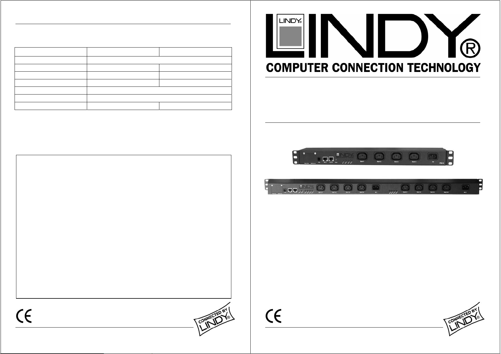
Components and Elements
1 Programming block (covered by protective plate)
2 Address DIP switches (covered by protective plate)
3 Serial RJ-10 socket for RS-232 access
4 Bus IN and OUT (cascading), RJ-45 socket
5 Bus IN and OUT (cascading), RJ-45 socket
6 Status LED for INPUT voltage 1
7 Status LEDs for OUTPUT voltage 1-4
8 Outlets 1-4 (230V AC)
9 INPUT 1 (230V AC)
8 port model only (No. 3245
10 Status LED for INPUT voltage 2.1-2.4
11 Outlets 2.1-2.4 (230V AC)
12 INPUT 2 (230V AC)
)
The supplied RS-232 cable (D9f to RJ-10) is used to connect the power strip to the RS-232 port of the devices
which manage the power strip (i.e. LINDY Rack Monitoring System, IP Access Switch Plus, etc.)
The power strip is powered using
OUTPUT STATUS LED’s
the power to the
different AC phases.
OUTLETs 2.1-2.4
INPUT 1 (9)
(7) show the power status of
- this provides the option to switch redundant power supplies, powered from
Cascading of multiple RS-232 Power Strips
Please make sure that there is NO connection to the mains when changes
When cascading multiple power strips over large distances the RS-485 bus
termination has to be enabled. To enable termination DIP switches 7 and 8 (under
the protective covers) have to be set to ON. This termination is required for any
bus lengths above 100m.
The power strips are equipped with an internal protocol converter (from RS-232 to
RS-485) to cascade multiple power strips. The cables used to cascade the power
strips are standard RJ-45 patch cables. Just connect the
power strip to the
cascaded all (up to 32) power strips.
. The power status is monitored by the
OUTLETs 1-4
are made to the DIP switches! Detach ALL power strips!
BUS IN
of the next power strip and continue until you have
. For the 8 port model,
INPUT STATUS LED
INPUT 2
BUS OUT
(6). The
(12) supplies
from the first
User Manual 3
Please make sure that there is NO connection to the mains when changes are made to
the DIP switches (Address settings and Bus termination)! Detach ALL power strips!
The Address DIP switch (2) is hidden behind a protective cover plate. The default setting is Address = 0.
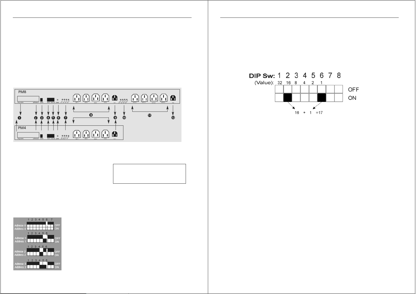
Up to 64 addresses can be set. DIP switch 1 refers to the highest bit (value=32), DIP switch 6 to the lowest
(value=1). All switches OFF means Address = 0.
Example : To set the address to 17( = 16 + 1), DIP switch 2 and 6 have to be "ON”. See below –
Please close the protective cover after address and termination settings have been made.
RS-232 Management
Detailed documentation about the RS-232 management protocol can be found on the supplied CD. The CD also
contains DOS programs and other tools which allow you to access the power strips from a computers RS-232 port.
For example, here are the commands available in the program PMODULE:
PowerModule V0.60
usage: PModule -dx [-i][-s[x]][-onx][-offx][-a[d]x][-tox][-f][-tx.xx][-v][-comx]
-d device address x (0..31)
-i read device type
-s read status from all outlets
-sx read status from outlet x (1..8)
-onx switch outlet x on (9 for all)
-offx switch outlet x off (9 for all)
-ax switch all binary
-adx switch all binary with delay
-tox toggle outlet x
-ponx t pulse outlet x on off with time t (1..16383 x 100ms)
-poffx t pulse outlet x off on with time t (1..16383 x 100ms)
-f find devices
-tx.xx timeout factor (-t1.25)
-v verbose
-comx use com x (1 or 2, default is 1)
Every cascaded power strip has to be set to its own address!
 Loading...