

Page 1

Technical Data
Model IPower Switch 4 LITE
Remote Access Port Ethernet 10Base-T, RJ-45
Input Voltage IN/OUT 1x IEC-Plug / 4x IEC-Socket 2x IEC-Plug / 8x IEC-Socket
Input 230VAC 2300VA (10A@230V) 230VAC 2x2300VA, 2x(10A@230V)
Output Max. 8A per outlet, total 10A Max. 8A per outlet, total 2x10A
Operating temperature +5°C ... 40°C, for in house use
Humidity 5 … 85% rel. H. non condensing
Measurements (HXWXD), weight 44.5 (1U) x 441 x 63 mm, 1.4kg 44.5 (1U) x 788 x 63 mm, 2.3kg
No. 32450
IPower Switch 8 LITE
No. 32451
European EMC Directive 89/336/EEC CE statement
This equipment complies with the requirement for CE mentioned in the European Directive 89/336/EC and
Standards EN55022 and EN55024.
FCC Warning
This equipment has been tested and found to comply with the limits for a Class B Digital device,
pursuant to part 15 of the FCC Rules. These limits are designed to provide reasonable protection
against harmful interference in a residential installation. This equipment generates, uses, and can
radiate radio frequency energy and, if not installed and used in accordance with the instructions, may
cause harmful interference to radio communications. However, there is no guarantee that interference
will not occur in a particular installation. If this equipment does cause harmful interference to radio or
television reception, which can be determined by turning the equipment off and on, the user is
encouraged to try to correct the interference by one or more of the following measures:
y Reorient or relocate the receiving antenna
y Increase the separation between the equipment and receiver
y Connect the equipment into an outlet on a circuit different from that to which the receiver is
connected
y Consult the dealer or an experienced technician for help
You are cautioned that changes or modifications not expressly approved by the party responsible for
compliance could void your authority to operate the equipment.
For Commercial Use
Tested to Comply with
FCC Standards
© LINDY ELECTRONICS LIMITED & LINDY-ELEKTRONIK GMBH - SECOND EDITION (JAN 2005)
IPower Strip LITE
User Manual
(Version 8/2004 Firmware Version 1.18, supplied version may be higher)
Model 1 IN / 4 OUT: LINDY No. 32450
Model 2 IN / 8 OUT: LINDY No. 32451
For Commercial Use
Tested to Comply with
FCC Standards
© LINDY ELECTRONICS LIMITED & LINDY-ELEKTRONIK GMBH - SECOND EDITION (JAN 2005)
www.LINDY.com
English
Page 2
English Manual
)
:
Features
• Remote Access Power Strip with remote management function via IP
• Switch one or all outlets using HTML commands or via a web browser
• Supports 4 or 8 users + 1 administrator; users have individual access rights
• Easy to use browser interface permanently shows the outlet status, and allows easy switching
• Supports a switch cycle with a user definable time interval - from 1 sec to 10 hours
• Automatic logout after user definable time interval - from 20 sec to 1 hour
Packing List (8 Port Model in brackets)
• 1 x Power Strip + User Manuals + CD
• 4(8) x mains cables, OUTPUT IEC-320 male – IEC-320 female approx. 1.8m
• 1(2) x mains cables, INPUT Schuko male – IEC-320 female approx. 1.8m
• 1 x Serial RS-232 cable, RJ-10 to D9-female, approx. 2m
Installation
The 4 port power strip is rack mountable in a 19”, 1U bay. The 8 port model can be mounted vertically. The
brackets can be adjusted to almost any position for maximum flexibility when installing.
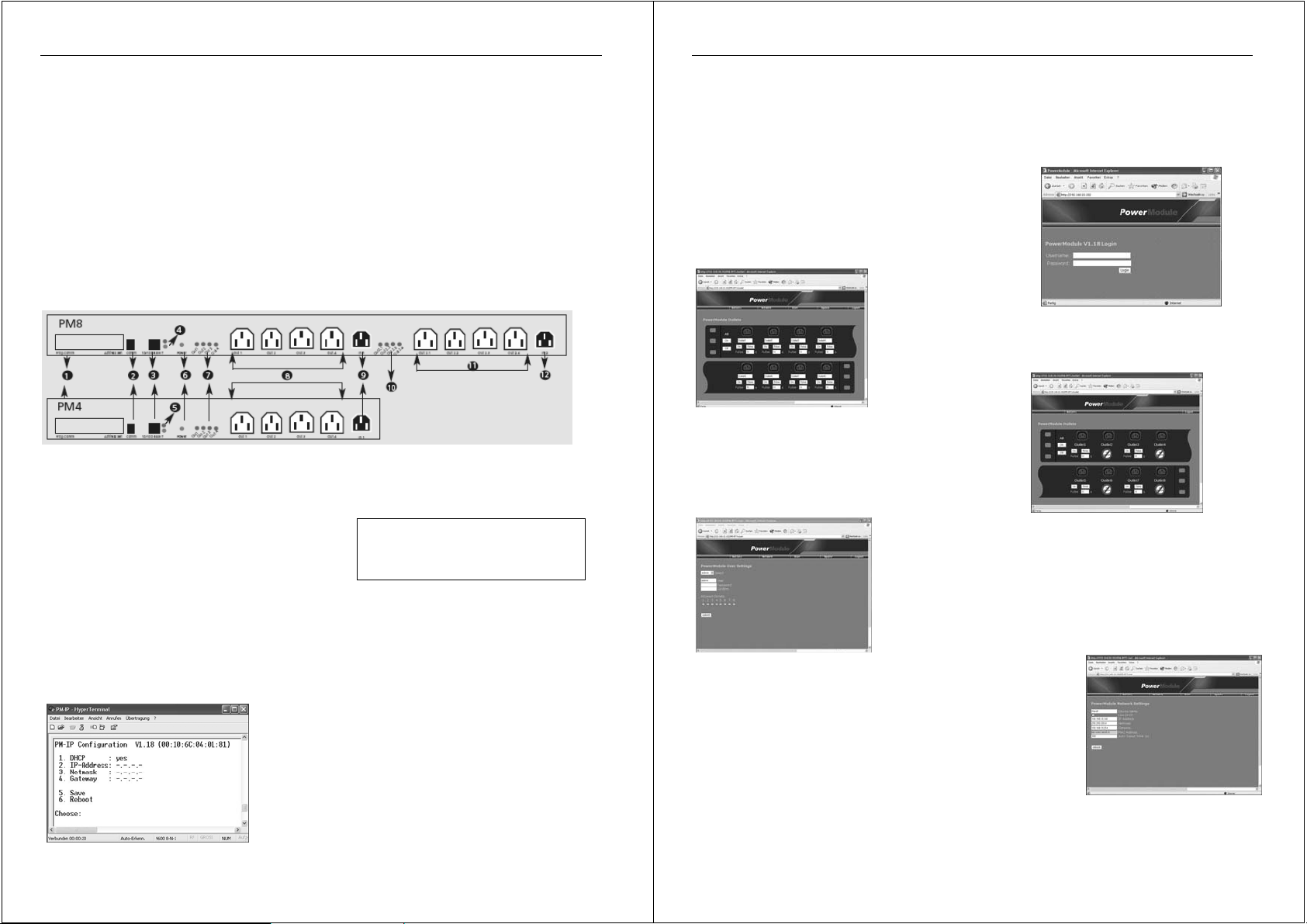
Components and Elements
1 Programming block (covered by protective plate)
2 Serial RJ-10 socket for terminal program access (initial setup)
3 Ethernet RJ-45 socket
4 Link / Activity LED
5 Link / Activity LED
6 Status LED for INPUT voltage 1
7 Status LED’s for OUTPUT voltage 1-4
8 Outlets 1-4 (230V AC)
9 INPUT 1 (230V AC)
8 port model only (No. 32451
10 Status LED f for INPUT voltage 2.1-2.4
11 Outlets 2.1-2.4 (230V AC)
12 INPUT 2 (230V AC)
Initial Setup
Network Address (Release 8/2004 V1.18)
The power strip comes with the DHCP setting enabled as default. To use the power strip in non DHCP networks
the IP address must be set manually, via an RS-232 serial connection to a computer running a terminal program.
The IP address is required to identify the power strip on your LAN.
Note:
The terminal program must be configured with the following settings:
Baud rate: 9600, Stop bits: 1, Parity: none; Handshake: off.
a) Use the supplied serial RS-232 cable (D9-f to RJ-10) to connect
the computer to the power strip. Launch the terminal program. After
pressing Return, the input menu opens up.
b) To change from DHCP to fixed IP mode, select (1) DHCP. The
menu will show the information “DHCP: n”.
c) Now edit the IP-Number, the Netmask and the Default Gateway
settings. (Ask your network administrator for the correct settings).
d) When you have edited all settings select (5) Save. To make the
new settings effective select (6) Reboot. After you have rebooted
the power strip, it will only be available using the new network
settings - the current terminal window will not respond!
2
English Manual
3
Connection to the mains power
The power strip is powered by
The correct power status is displayed by the
immediately show the status of
INPUT 2
by
phases.
Usage
The power strip includes a web server which is available via IP
access, using a web browser on your network. Type the IP address
in your web browser window and the power strip will display the login
screen.
The first time you access the power strip you must log in as admin Username: admin, Password: admin
The power status of each outlet is displayed graphically via
illuminated LED’s next to each socket (red=ON, dark=OFF). You
can select the switch buttons, which also display the action to be
taken. The name and duration time can be changed by editing the
values. When selecting the buttons “All” or “Off”, the outlets will
be switched accordingly.
change the IP settings via the menu item - “Network”. To make the
new settings effective click the “Reboot” button. When you have
rebooted the power strip it will only be available using the new network
settings. The administrator can edit the default logout time (60 sec.) to
any value from 20 sec to 1 hour.
The power strip also can be switched via HTML commands (httpget)
Please see the following syntax examples:
http://ip/switch?u=user&p=passwd&o=n&f=func
http://ip/switch?s=0 (display status)
The following parameters can be used - ip: ipaddress // user: username // passwd: password // n: outlet number to
switch // func: on or off or pulse or toggle*.
*Toggle is delayed switching (not available from the browser menu)
while pulse is a single switch cycle
. This provides support for devices with redundant power supplies, powered from different AC
(Release 8/2004 V1.18)
INPUT 1
(9). Attach the supplied power cable to
OUTLETS 1-4
INPUT STATUS LED
(8). For the 8 port model, the
(6). The
INPUT 1
OUTPUT STATUS LED’s
OUTLETS 2.1-2.4
, and then to the mains.
(10) are powered
The power strip displays a
graphical user interface where the single outlets can be switched. Further
settings can be made via the top menu list: Outlets, Network*, User*,
Update*, Logout (* only available for admin).
The power strip web server provides for up to 4 or 8 users, each
with individual access rights and passwords. The administrator can
edit users via the top menu item “User”. The box “Select User”
allows one of the available preset users to be selected. Names and
passwords can be edited here, and access rights to each outlet
can be set by clicking “Allowed Outlets”. To make changes
effective the “submit” button has to be clicked – the power strip
will reboot. Now when a user accesses the power strip he can only
access and change values of the sockets for which he is permitted.
The administrator can
(7) will
 Loading...