

Page 1
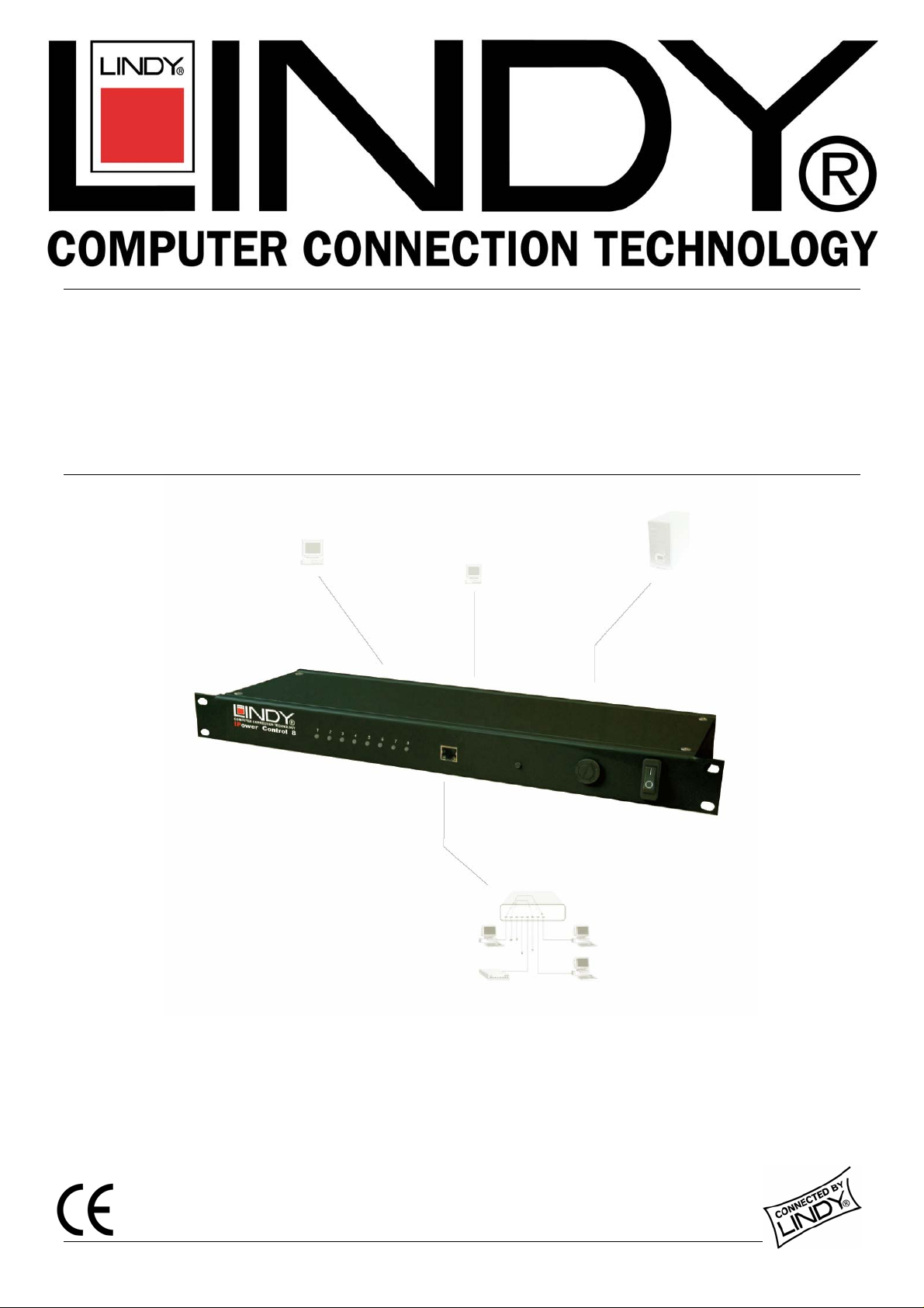
IIPPoow
weerr CCoonnttrrooll 88
User Guide English
LINDY No. 32416
www.lindy.com
© LINDY ELECTRONICS LIMITED & LINDY-ELEKTRONIK GMBH - FIRST EDITION (May 2005)
Page 2
1. CONNECTION
Connect the IPower Control unit to the mains and to your Ethernet network. There are eight
LEDs at the front of the unit which relate to the switching state of the ports. When using the
IPower Control for the first time all LEDs will simultaneously light up red.
When reconnecting the IPower Control to a power supply the LEDs will light up successively
(during this procedure the IPower Control is not available via a web browser). Depending on
the ports switching state the LEDs will illuminate red (port is switched off) or green (port is
switched on). If the IPower Control is additionally connected to an existing Ethernet network a
green LED next to the LAN input will illuminate.
An IP address must be allocated to the IPower Control in order for it to switch via Ethernet. The
IP address must belong to the desired sub network. The allocation can be accomplished either
manually or automatically by a DHCP server (see 2.1 below). For manual allocation under
Windows, we recommend the program IPCnet_conf.exe
*1
(see 2.2).
After modifying the IP settings the IPower Control can be switched by all PCs on the same
network via the website of the IPower Control.
2. IP SETTINGS
2.1 Allocation by DHCP
If there is a DHCP server available on the network an unused IP address will be allocated
automatically each time the IPower Control is connected. This option can be disabled (see
section 6) or modified by appropriate configuration of the DHCP server.
2.2 Allocation via software
*1
(Windows only)
Start the IPower Control in boot
mode (see section 7) and launch
the IPCnet_conf.exe program.
The program will automatically
search for connected devices
and display their IP settings. If
the displayed IP address
matches the default setting
(192.168.0.2) there is either no
DHCP server available or no
unused IP address could be
allocated.
Enter an unused IP address and the gateway of the desired sub network. Save changes with
Program Device/SaveConfig.
After changing the network settings the IPower Control must be restarted
*2
in normal mode
(see section 7). After restarting click on Search in order to display the modified settings.
*1 Available from our website www.lindy.com
*2 Restart means unplug and then re-plug the IPower Control to the mains.
Page 3
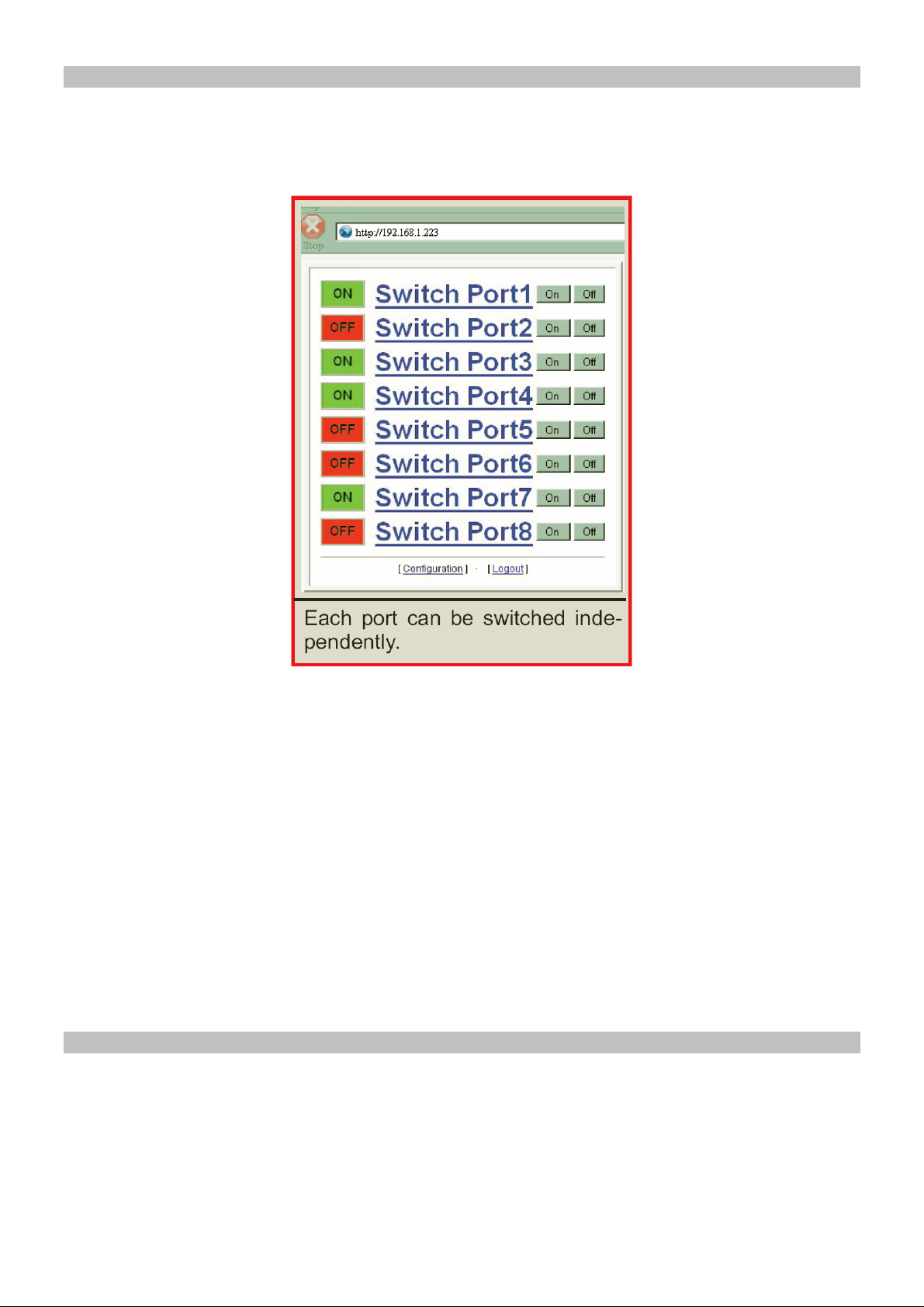
3. SWITCHING VIA ETHERNET
Login to the website of the IPower Control, http:// “IP Address of IPower Control” (e.g.
192.168.0.2). You may need to enter a password (see section 6). Now you can choose a port in
order to reset it or switch it directly.
The following options are available:
Configuration
The settings of the IPower Control and the single ports can be configured here (see section 4
below)
Logout
Only one user can be logged in at a time. After three minutes inactivity there will be an
automatic log out.
Having chosen a port it can be switched or reset.
Reset
Independently of the current switching state, the port will be switched on after the chosen delay,
i.e. the connected device will be turned on.
4. CONFIGURATION
Via the website of the IPower Control, you can access the configuration menu. To modify the
settings of a port, choose it from the roll-up menu in the upper part of the configuration menu
(Port Configuration, section 5). The IPower Control settings can be modified in the lower part of
the menu (Network Configuration, section 6).
Modifications to name and password will be applied immediately. To apply modifications to
other settings, the IPower Control must be restarted.
Page 4

5. PORT CONFIGURATION
The ports can be selected individually from the roll-up menu at the configuration site. The
following settings can be modified for each port:
Label
A name with a maximum of 15 characters can be entered here.
After Power Up switch
The ports state after a restart of the IPower Control can be defined here (on, off, last state)
Delay
A delay for the following port can be chosen here. That is, in case of a restart the following port
will be switched after the chosen delay (1-30 sec). E.g. a delay of 5 seconds for port 2 means
that port 3 will be switched 5 seconds after port 2.
Page 5

6. NETWORK CONFIGURATION
The following settings can be modified in the configuration menu:
Device Name
A name with a maximum of 15 characters
can be allocated here.
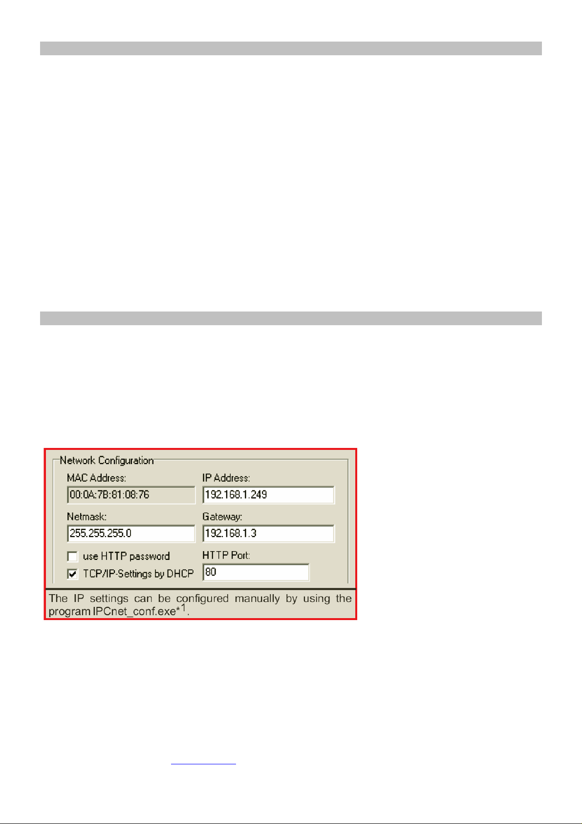
IP Settings
The IP settings of the IPower Control can
be modified here.
HTTP Port
If required, the port number of the internal
web server can be allocated here. Values
from 1 to 65534 are possible (default: 80).
After changing the port number the IPower
Control must be restarted. The modified
port number will be added to the IPower
Control’s address (http:// “IP Address of
IPower Control:Port number” e.g.
192.168.0.2:6)
TCP/IP settings by DHCP
Each time the IPower Control is restarted
it will be checked if a DHCP server is
available on the network. In this case the IP
settings will be requested and saved. If
there is no DHCP server on the network it
is advisable to disable this option.
Password
Access protection can be allocated here. If
access protection is required, both a user
and admin password with a maximum of 15
characters have to be defined.
An administrator is authorized to switch and
reset each port as well as modify the
settings of both ports and the IPower
control. The admin password is ‘admin’.
A user is authorized to switch and reset each port. (A user is not authorized to modify the
settings of the ports or the IPower Control). The user password is ‘user’.
Page 6

7. OPERATING MODES
The IPower Control can be started in two ways:
Boot Mode
To start the IPower Control in boot mode, the button at the front must be pushed for at least
two seconds when restarting the unit. Using the IPCnet_conf.exe program it is possible to
disable password protection, to upgrade the firmware and to restore the default settings.
When the IPower Control is in boot mode all ports are switched off (all LEDs are red), it is not
possible to reset or change the switching state of a port.
Normal mode
After a restart the IPower Control is in normal mode automatically. In normal mode the ports
can be switched and the settings of both the ports and the IPower Control can be modified.
8. CHANGING SWITCHING STATE
A device which is connected to a
port can be turned off and on again
by using the reset function (see
section 3).
The current switching state of port 1
can be changed by pushing the
button at the front side of the IPower
Control for at least 3 seconds.
9. FIRMWARE UPGRADE
In order to upgrade the firmware both the IPCnet_conf.exe program and the latest firmware
(available from www.lindy.com) are needed.
Start the IPower Control in boot mode (see section 7) and launch IPCnet_conf.exe. On the left
hand side of the program window all IPower Control units which are on the network are listed.
Select the one which is to be upgraded and click on Program Device/Firmware upgrade.
LEDs
There are eight LEDs on the front of the IPower Control, each of which relates to the switching
states of the respective port as follows:
(Red) The IPower Control is connected to an electric circuit and the power is switched off
(Green) The IPower Control is connected to the mains and the port is switched on.
(Off) The IPower Control is not connected to an electrical circuit
Page 7

10. DEFAULT SETTINGS
ps)
In order to restore the default settings the IPower
Control must be started in boot mode (see section
7). Launch IPCnet_conf.exe.
After the program has opened, all IPower Control
units which are on the network will be listed on the
left hand side of the program window. Select the
one for which the setting should be restored and
click on Program Device/Format Eeprom.
Please note that all current settings will be deleted.
When the IPower Control is restarted the default
settings will be loaded.
After the default settings have been restored the
IPower Control must be set up again (section 1).
11. TECHNICAL DATA
Network Connection: 10Mbit 10Base-T Ethernet
Network protocol: TCP/IP
Switched power (per port): max. 2000W
Switched power (total): max. 3000W
Operating temperature: 0
o
C – 50oC
Dimensions: 19” / 1U height
Note: The IPower Control was developed for use with IT devices. Using the
IPower Control with devices which have a high initial current surge (like halogen
lam
is not recommended.
Page 8

12. FAQs
Connection
The IPower Control is connected to a network but...
...the LEDs do not illuminate
Please check the connection to the electrical circuit
...the green LED at the LAN socket does not illuminate
Please check the network connection
...I can’t open the website
Please ensure that both the IPower Control and your PC are on the same sub network
Where can I find the IP settings of my sub network?
Open an MS-DOS command prompt and enter the command: ipconfig/all
How can I check if the IPower Control is connected properly?
Launch IPCnet_conf.exe and click on Search. If the IPower Control is connected properly it
will be displayed in the left part of the program window.
Switching
I can’t log in to the IPower Control’s website
If the message “Access denied. Used by…” is displayed, there is another user logged in at
the moment.
Alternatively, check the network connection (the green LED at the LAN socket must be lit) and
ensure that both the IPower Control and your PC are on the same sub network.
I can’t change the settings in the configuration menu
Log in as administrator (see section 6).
The switching state of port 1 doesn’t change when pushing the front button
Restart the IPower Control in normal mode.
IPCnet_conf.exe program
The IPower Control is not found by the program
Check the connections to the electrical circuit (the LEDs at the front must be glow green or red)
and the network (LED at the LAN must light up green).
 Loading...