

Page 1

CPU Switch MultiMedia 2X8
Manual English
Benutzerhandbuch Deutsch
2 User @ 8 PC, LINDY Art. Nr. 32812
4 User @ 8 PC, LINDY Art. Nr. 32814
© LINDY ELECTRONICS LIMITED & LINDY-ELEKTRONI K GMBH - FIRST EDITION (DEC 2001)
Page 2

English Manual 1
Packing List / Packl iste
The complete LINDY CPU Switch MultiMedia package consists of:
1. 1 LINDY CPU Switch MultiMedia
2. 1 Power Adapter
3. 2 Rack Mounting Brackets (screws included)
4. 4 Stacking Elements
5. 1 LINDY User Manual
Please read this manual thoroughly, and follow the installation and operation procedures
carefully to prevent any damage to the LINDY CPU Switch unit, and/or any of the devices
connected to it. We have tried to keep this manual as short as possible but complete
also.
Table of Contents
Overview...............................................................................................................1
Features................................................................................................................1
Hardware Requirements ......................................................................................3
Cables.....................................................................................................................
Front panel switches and connectors ......................................................................
Installation...............................................................................................................
Operating the CPU Switch ....................................................................................1
OSD Operation......................................................................................................1
Function Keys .......................................................................................................1
Troubleshooting....................................................................................................1
Specifications........................................................................................................ 2
Stacking and Mounting..........................................................................................2
CE Conformity, Warranty......................................................................................2
© LINDY ELECTRONICS LIMITED & LINDY-ELEKTRONIK GMBH - FIRST EDITION ( DEC 2001)
Page 3

English Manual 2
Overview
The LINDY CPU Switch is ideally suited for the following:
KVM access for keyboard, video (monitor), mouse and stereo audio
Simultaneous access from up to 4 independent consoles / users for up to 8 PCs.
The CPU Switches are not cascadable with each other or themselves. If you need more than 8
PCs connected you should use non-multi-user CPU Switches in the upper cascade near the
consoles. At the moment LINDY is preparing the introduction of new audio enabled CPU
Switches: Please read t he latest news at www.lindy.co.u k, in t he LINDY catalogues or the LINDY
newsletters.
The installation of the system is quick and simple. You only need to install the units and connection
cables. There is NO configuration software, other software, jumper settings or anything to be done. This
is a pure hardware concept that therefore causes no software incompatibles. The LINDY CPU Switch
operates with almost any hardware platform as long as it complies with PC compatible standards.
The LINDY CPU Switch MultiMedia offers you the most efficient and ergonomic solution to access
multiple servers from multiple consoles / users independently at the same time. No more running
between different server enclosures, just operate all machines from your regular desk
(speaker + microphone).
The switching between the connected PCs / servers is easily done by selecting the PCs from
the On-Screen-Display (OSD) of the CPU Switch. All PCs are displayed arranged together with
their given name and status of operation. If another user operates a particular PC, then the
OSD will show a simple message to inform you. An extended Auto-Scan mode makes it
possible to view all connected PCs, one after the other by a definable dwell time.
Features
w
Multi-User Access up to 8 PCs
w
Access to all PCs without changing desk
w
Full Audio Stereo Support
w
PC selection via OSD (On-Screen-Display)
w
Multi-Level & Multi-User password protection
w
Quick View Scan function for watching all connected PCs
w
Permanent emulation of all console peripherals ensures simultaneous boot-up without
selecting the PCs directly
w
Support of PS/2 compatible as RS-232 mouse connections at the PCs
w
Support of wheel mice, like the, LINDY Dual Wheel Mice, Microsoft IntelliMouse Explorer
and Logitech FirstMouse*.
w
High Resolution Video Quality up to 1920 x 1440 @ 75Hz; DDC Support
w
Desktop housing with stacking elements or 19“ Rack-mountable – mounting brackets
included
w
Hot-plug-enabled, PCs can be disconnected and reconnected during operation of the
CPU switch
* PS/2 compatible mice include 3 button mice and wheel mice. The function Change Device in
the program Logitech Mouse Ware does not work on Wi ndows NT systems.
It is strongly recommended to use MICROSOFT drivers for all Logitech products.
© LINDY ELECTRONICS LIMITED & LINDY-ELEKTRONIK GMBH - FIRST EDITION ( DEC 2001)
Page 4

English Manual 3
Hardware Requirements
Console
w
VGA Monitor for resolution up to 1920 x 1440 Pixel, up to 75 Hz
w
PS/2 compatible mouse
w
PS/2 compatible keyboard
w
Audio Stereo microphone and speaker, optional
PC
w
VGA graphics card
w
6 pin Mini DIN (PS/2) or 9 Way D (standard serial-port) mouse connection *
w
PS/2 keyboard port (6 pin Mini DIN) or AT keyboard port (5 pin DIN, 5V on Pin 5,
ground on pin 4)
w
Audio Stereo Input/Output for microphone and speaker, optional
* At a PC with a 9 Way D Type port, a PS/2 – serial adaptor (LINDY Art. No. 70058) has to
be used. The adaptor cable for the AT keyboard port is LINDY Art.No. 70139
Cables
Because of limited space on the rear side of the CPU switch and the many necessary connections to be
made, special system cables have to be used with this CPU Switch.
The first two consoles are connected via standard connection cables for SVGA, PS/2 and Audio Stereo
with 3.5mm Stereo connectors, but also LINDY KVM cables including SVGA and 2x PS/2 can be used
together with standard LINDY audio cables. To connect the consoles 3 and 4 of the CPU Switch
MultiMedia 4x8 special system cables ha ve to be used.
Console to L INDY CPU Switch:
Length Art. No. Description
2m 33801 Monitor/Mouse/Keyboard/Audio-Console-Cable (2x PS/2 + 1x VGA + 2x Audio)
5m 33803 Monitor/Mouse/Keyboard/Audio-Console-Cable (2x PS/2 + 1x VGA + 2x Audio)
PC to LINDY CPU Switch: (uses special system cables)
Length Art. No. Description
1,5m 33811 Monitor/Mouse/Keyboard/Audio-Cable (2x PS/2 + 1x VGA + 2x Audio)
3m 33812 Monitor/Mouse/Keyboard/Audio-Cable (2x PS/2 + 1x VGA + 2x Audio)
5m 33813 Monitor/Mouse/Keyboard/Audio-Cable (2x PS/2 + 1x VGA + 2x Audio)
Extension Cables:
A wide range of extension cables can be found from LINDY:
- Combo extension cables for KVM, 1m up to 10m
- Standard extension cables, available also for audio up to 10m
© LINDY ELECTRONICS LIMITED & LINDY-ELEKTRONIK GMBH - FIRST EDITION ( DEC 2001)
Page 5
English Manual 4
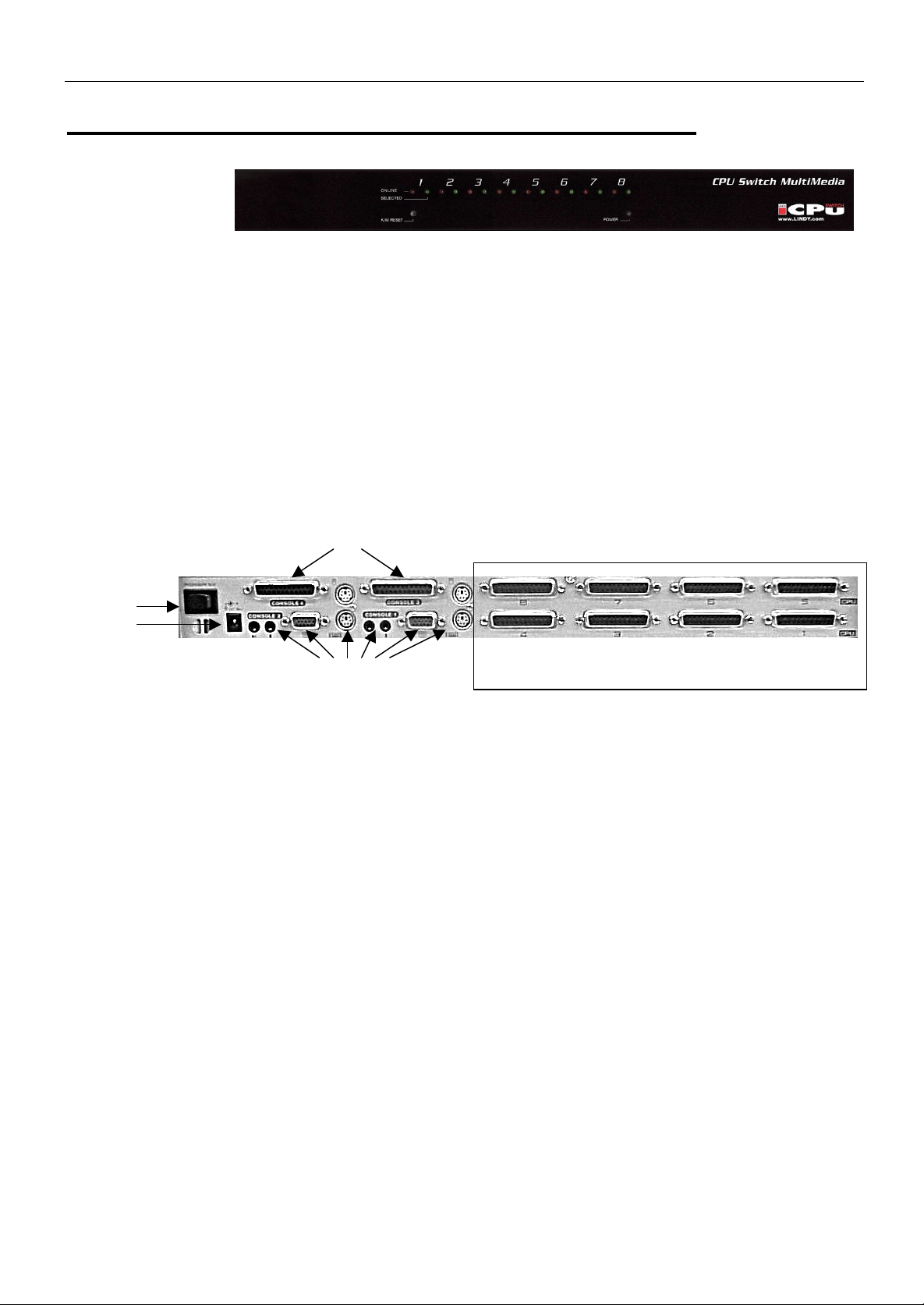
Front View and Keys and Backside Connectors
1 – Port LEDs:
All 8 switches for the appropriate PCs have two status LEDs.
ONLINE:
SELECT:
2 – K/M Reset
If the keyboard and mouse get stuck and need to be reset, carefully insert a pointed object in
here and push.
5 – Power LED
Lights blue to indicate that the LINDY CPU Switch MultiMedia is turned on and receiving power.
1
2
1 – Power switch ON/OFF
2 – Power Input Jack
From external power supply, 9V DC, 1,2 A, positive on centre pin.
3 – Console connectors for CONSOLE 1 and CONSOLE 2
Connectors for monitor, mouse, keyboard, microphone and speakers. To be used with standard
cables.
4 – Console connectors CONSOLE 3 and CONSOLE 4
Connectors for monitor, mouse, keyboard, microphone and speaker s. To be used with LI ND Y system
cables only, see chapter CABLES.
5 – PC, Workstation, Server Ports
Ports to connect the PCs or cascaded CPU Sw i tches. To be used w it h LI N DY system cabl e onl y, see
chapter CABLES.
LED lights orange and shows that the connected PC is online. If this LED flashes
orange it means that this port is cascaded to another CPU switch.
LED lights green: the attached PC has just been selected by another user. LED
Stops when the PC is again available for access.
4
5
© LINDY ELECTRONICS LIMITED & LINDY-ELEKTRONIK GMBH - FIRST EDITION ( DEC 2001)
Page 6

English Manual 5
Installation
BEFORE YOU BEGIN
1. Make sure th at power to all the devices you will be connecting up have
been turned off. You must unplug the power cords of any computers that
have the Keyboard Power On function. O therwise, th e switch will receive
power from the computer.
2. To prevent damage to your equipment due to ground potential difference,
make sure that all devices on the installation are properly grounded.
Consult your dealer for technical details, if necessary.
Single Stage Installation
For an installation without cascading please use the following steps:
1. Connect the console cables to keyboard, mouse, monitor, speakers and microphone.
2. Connect the PCs with the appropriate PC ports of the CPU Switch. Use the appropriate LINDY
systems cables as described before in chapter CABLES.
3. Connect the enclosed power supply to the mains and plug in its DC power cable to the CPU
Switch.
4. Switch on the CPU Switch.
The Switch now undergoes a short Power-On-Self-Test. If there is a problem the LEDs will flash
according to one of the following patterns:
LED Lighting Pattern Indication
ONLINE LEDs 1-8 flash simultaneously Internal RAM memory error
ONLINE LEDs 1-8 flash one after the other External RAM memory error
ONLINE LEDs 1-8 pairs flash: 1+2, then 3+4, then
5+6, then 7 + 8, one after the other pair.
If any of these occur turn off the switch and then turn on again. If this does not help please
detach all cables from the rear side of the CPU Switch and turn off and switch on again. If the
error still is pres ent please contact the L INDY support hotline or your local dealer.
5. Complete all cable connections to the PCs that shall be connected.
6. Switch on all the PCs only after this procedure is complete.
© LINDY ELECTRONICS LIMITED & LINDY-ELEKTRONIK GMBH - FIRST EDITION ( DEC 2001)
ROM Test error
Page 7

English Manual 6
Installation of cascaded LINDY CPU Switches
At the moment no LINDY CPU Switches with integrated Audio support are available for cascading.
Please check for new products on the LINDY homepage www.lindy.com
IMPORTANT: The LINDY CPU Switch Multimedia 2x8 and 4x8 cannot be cascaded with each other.
Users that do not require the audio function but multiple user access may use one of the following
possibilities for cascading:
(1) Solution for non fully simultaneous access for a certain amount of servers:
Users are connected to the CPU Switch MultiMedia. The CPU Switch MultiMedia can be
connected to up to 8 PCs or LINDY CPU Switch LITE OSD-8 in the second cascade. The
maximum number of servers connected is 64 servers. Restriction: only one user c an acc ess the
PCs connected to the second stage units CPU Switch LITE OSD-8 at the same time. The other
uses have to wait until the previous user ends the access.
(2) Solution for fully simultaneous access for a certain amount of servers:
Users are connected to the CPU Switch LITE series switches (LITE OSD-8 or LITE-2 or LITE-4).
Multiple CPU Switch MultiMedia can be cascaded to the ports of the CPU Switch LITE, each
CPU Switch MultiMedia to one port of the CPU Switch LITE’s. Fully simultaneous access for
instance is possible up to 4 users and 32 servers by using 4 CPU Switch LITE-4 or OSD-8 and 4
CPU Switch MultiMedia 4x8. Restriction: No audio support.
To set up a cascaded installation over two stages please follow the following steps:
1. Make sure the power is switched off at all units that will be insta lled in the syst em including PCs.
2. Connect all cable connections using the appropriate LINDY system cables and/or LINDY 3-in-1 KVM
cables (refer to section CABLES).
3. Switch on first the devices and CPU switches in the first stage at the user consoles.
4. After they have completed their boot-up procedure switch on the CP U Sw i tc hes i n the sec ond stage.
5. After they have completed their boot-up procedure switch on the CPUs, servers and PCs.
Please note: to ensure proper operation, please make sure to follow the sequence in the
aforementioned order.
to find new product releases.
© LINDY ELECTRONICS LIMITED & LINDY-ELEKTRONIK GMBH - FIRST EDITION ( DEC 2001)
Page 8
English Manual 7
Operating the CPU Switch MultiMedia
Hot-Plugging
LINDY CPU Switch MultiMedia supports ‘Hot-Plugging’. This means single components like PCs,
cascaded LINDY CPU switches, and mice, etc. can be removed and reattached to the installation
without powering down and rebooting the CPU Switches on the installation. To ensure proper
functionality in this case some rules have to be regarded:
If cables (or devices) are removed from the installation they can only be reattached at the same
position/port. The type of mouse cannot be changed. The mouse should be reattached before the
keyboard gets reattached. After the cables and unit is reattached, a RESET has to be performed via the
front side RESET switch at the CPU Switch. But also just switching between different ports may cause
the devices to function properly again.
Powering down and restarting
If it is neces sar y to sw i tch off single C PU sw i tc hes or the c om plete i nst all ati on pl ease foll ow the follow ing
steps:
First pow er dow n al l PCs or dow nstr eam cas caded C PU s wi tc hes and PC s connec ted to the CPU s wi tc h
you want to power down. Then power down the CPU Switch itself.
Please note:
Also the mains cables of all PCs that support the ‘Keyboard Power On’ function have to be unplugged.
Alternatively all keyboard and mouse cables may be unplugged. Otherwise the CPU Switch will still be
powered on via the PCs and their keyboard and mouse connections.
Switch off the CPU Switch or unplug the power supply from the mains. Wait for approximately 10
seconds until you power the units on again.
When powering on follow the order m enti oned above i n the or der st ar ting from the c onsol es goi ng dow n,
stage by stage until the PCs.
PC / Port selection: OSD (On-Screen-Display)
All PCs connected to the CPU Switch can be easily
selected by OSD.
The OSD is used to display and select all connected PCs
and their status of operation clearly.
Every attached PC can easily be given and identified by a
user selectable name.
The port selection can be done by moving the cursor up
and down. Alternatively you can use the mouse cursor,
highlight and click the selected choices in the OSD.
© LINDY ELECTRONICS LIMITED & LINDY-ELEKTRONIK GMBH - FIRST EDITION ( DEC 2001)
Page 9

English Manual 8
The OSD is activated by pressing the CONTROL key twice. This hotkey can also be changed to the
SCROLL LOCK key.
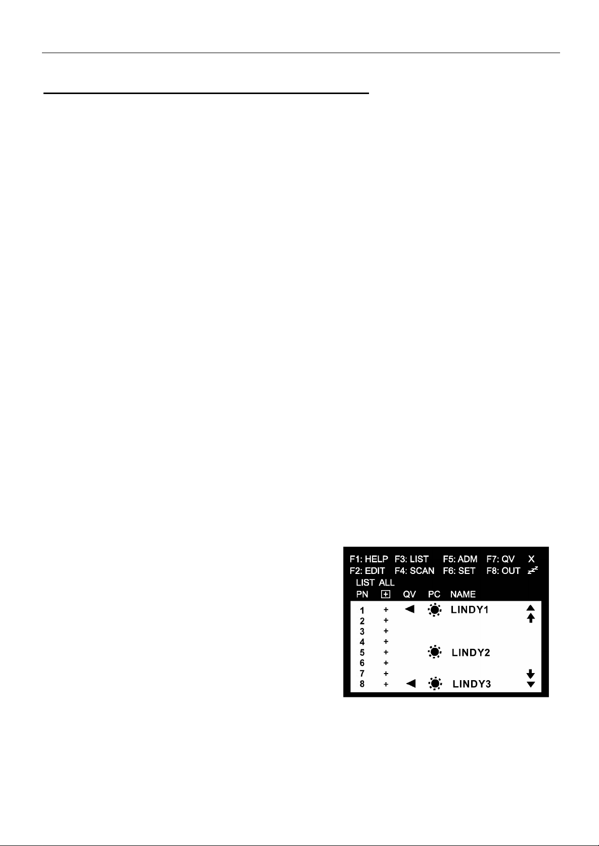
OSD Main Menu Information
Heading Explanation
This column li sts the Por t- I D - num ber s for al l C PU Por ts. The m os t si m ple m ethod to
PN
+
select a port is to move the highlighted line to the selected port using the cursor
keys and then pressing the ENTER key or to select and click the port using the
mouse.
The symbol + marks the ports that can be accessed from this console. Ports not
showing the + symbol cannot be accessed (see also password protection and multi
level user rights)
QV
PC Lists all ports/PCs that are connected and powered up with a symbol like a sun.
NAME If a name was given it will b e showed here.
For security purpose the OSD also includes a multi level password protection for up to 4 users and one
administrator. Single users have different passwords and can have different access rights.
In factory default setting the password protection is disabled. All consoles log in with administrator rights
and complete access. Password protection is enabled via OSD.
The following function keys are used to configure and control the switch via OSD menu:
F1 HELP Basic HELP list of OSD menu options
F2 EDIT Edit and enter the OSD names of attached servers
F3 LIST Edit the settings and select the display lists of the OSD
F4 SCAN Edit the Auto-Scan list and settings
F5 ADM Administration of the switch, passwords, rights, ... (administrator only)
The triangle symbol marks all ports that are selected for the Quick-View-Scan-
Mode.
F6 SET Administration of individual consoles, settings and user password
F7 QV Start Quick-View-Auto-Scan Mode
F8 OUT Logs out the c onsole, Log in only with password
© LINDY ELECTRONICS LIMITED & LINDY-ELEKTRONIK GMBH - FIRST EDITION ( DEC 2001)
Page 10

English Manual 9
OSD Functions
Navigation via OSD Menu
w
[ESC] goes up one level higher in the OSD. When already in highest level the OSD will be closed.
w
Use cursor Up/Cursor Down keys to move the highlighted bar. To make selections then press
ENTER.
w
Or click with the mouse at the triangle symbols (▲▼) or move the highlighted mouse cursor and
click the options to be selected.
w
After having made a selection the OSD automatically will go one level up or quit the OSD when
already in highest level.
ATTENTION:
(1) If a port or server was switched to PRIVATE MODE by a user, the screen will stay dark when
another user selects this port. The OSD will display a me ssage ‘Port is in private mode’.
(2) If a port or server is already being used and operated by another user the server screen will
appear and the OSD displ ays the m ess age ‘Port is in use’. Input to this server or por t is pos si ble
until the first user is disconnected (see F5 ADM / Set Access Timeout). Also if cascaded no input
to this port is possible AND the screen stays dark.
OSD Display window of selected port / server
The OSD can show the s elec ted por t / ser v er per m anentl y in a small w i ndow includi ng the ac ces s s tatus .
These settings can be adjusted via OSD Menu F6 CHANNEL DISPLAY DURATION and CHANNEL
DISPLAY POSITION.
Status information:
- S in front of the port number marks that this port is regularly accessed.
- S and R in front of the port number marks that this port can be displayed only, for instance because
another user is using the attached server. Input to this port is not possible as long as SR is displayed.
z
Z
- Z
in fron t of th e port number marks that this port will be free for access by other u sers afte r the
adjustable ‘ACCESS TIMEOUT’ time (2-255 sec., F5 SET ACCESS TIMEOUT) has passed.
- P in front of the port number indicates that this port is set to Private Mode by another user. The
monitor shows the OSD message ‘PORT IN PRIVATE MODE’ only.
Port Numbering
The port-ID is a one or two digit number. All servers connected directly to the CPU Switch MultiMedia
have a one digit port-ID (1 to 8).
© LINDY ELECTRONICS LIMITED & LINDY-ELEKTRONIK GMBH - FIRST EDITION ( DEC 2001)
Page 11

English Manual 10
Function Keys F1 to F8
The function keys invoke an OSD sub menu used to configure and control the CPU Switch. Following
the list of Function Keys and their meaning.
w
F1 HELP:
Displays a list of Basic HELP functions of the OSD menu options.
w
F2 EDIT:
This is an administrator function!
The administrator can provide and edit names to the ports and attached servers. After selection of the
port the name is entered via sub menu F2. The following characters are allowed, lower case will be
regarded as upper case: a-z, A-Z, 0-9, +, -, /,:, . and ‚space’.
The ENTER key i s us ed to inv oke the c hanges and l eads bac k one m enu l ev el higher. ESC qui ts w i thout
changing the previous settings.
w
F3 LIST
This function is used to configure a console!
A sub menu is displayed allowing editing and changing of the information displayed in the OSD and the
auto scan settings.
Choice Meaning
ALL Lists all Ports and servers with their name
QVIEW Lists only the ports having been selected for auto scan
POWERED ON Lists only the ports where servers are attached and powered on
POWERED ON +
QVIEW
QVIEW + NAME Lists only the ports having been selected for auto scan and having been
NAME Lists only the ports having been assigned a name
To select an option, move the highlighted bar and press ENTER. Or select and click with the mouse. A
symbol will show u p in the QV column in the OSD for this p ort.
Lists only the ports where servers are attached and powered on and are
selected for auto scan
assigned a name
w
F4 SCAN
Pressing or clicking the F4 key activates the auto scan mode.
The auto scan mode can be released only by pressing the space bar!
In auto scan mode the screen show the selected server and a small window showing the basic
port information as described above. The list of servers for the auto scan mode can be edited
via F3 LIST.
© LINDY ELECTRONICS LIMITED & LINDY-ELEKTRONIK GMBH - FIRST EDITION ( DEC 2001)
Page 12

English Manual 11
w
F5 ADM:
Only available for the administrator!
F5 opens a sub menu showing options for the configuration of the CPU Switch MultiMedia. Please note
that changes will aff ect all users that are logged in as administrator at the same time.
The following sub menus will be listed:
Setting Function
SET PASSWORD This function is used to set passwords for the Administrator and User:
One Administrator and four User passwords can be set. Move the
highlight bar to User or Administrator, then press [Enter]. A screen that
allows you to key in your password appears. The password maybe up to
8 characters long and can consist of any combination of letters and
numbers (A - Z, 0 - 9). You are asked to key the password in twice to
make sure there is no typing mistake.
To modify or delete a previous password, use the backspace key. If the
Administrator wants to change a user’s password, he must enter their
administrator’s password first.
SET ACCESSIBLE
PORTS
SET ACCESS
TIMEOUT
CLEAR THE NAME
LIST
RESTORE
DEFAULT VALUES
RELEASE ALL
PRIVAT
SET LOGOUT
TIMEOUT
SET MULTIUSER
MODE
This function allows Administrators and Users to select, which Ports can
be accessed, from a particular Console.
If access is ON, a plus mark ( + ) has to be selected, space ( ) means
that access is not poss i ble. Sel ect ion i s m ade by ENT ER or SPAC EBAR .
A Multi-User Switch provides access to the selected ports to other users
after the selectable delay TIMEOUT. TIMEOUT is adjustable from 2-255
seconds. The time count starts after the last keyboard or mouse
operation. Selecting “0” means that the port will be permanently blocked
for all other users.
This function is used to undo all Administrator changes and return to
the original factory default settings.
Note: While this function is in progress, make sure that no other
operations are performed on any of the other Consoles.
This function is used to undo all Administrator changes and return to
the original factory default settings - except for the Names that were
assigned to Ports
Releases all Ports that have been set to Private Mode (see Private
Mode), so that they become accessible to all Consoles.
If a Console that has access ed by a c omputer i s not used for the am ount
of time set with this function, the Operator is automatically logged out. A
log in is necessary before the Console can be used again. This enables
the other Consoles to gain access to the computers when the original
Console is no longer accessing them, but the Operator has forgotten to
relinquish access. To set the timeout value, key in a number from 1-255
minutes. If the number is 0 [zero], this function is disabled. Default is 5
(five) minutes.
This function determines whether the same ID can be used to log into
the CPU Switch Mu ltiMedia from different Consoles at the same time.
1. If Disabled, the same ID cannot be used; if Enabled (the default),
the same ID can be used to log in from more than one Console.
2. If Enabled, the F4, F6, and F7 settings set for any one Console,
will be the same for all othe r Consoles t hat log in with the same ID.
3. Changes made to the F4, F6, and F7 settings by any logged in
Console will automatically affect all Consoles with t he same ID.
© LINDY ELECTRONICS LIMITED & LINDY-ELEKTRONIK GMBH - FIRST EDITION ( DEC 2001)
Page 13

English Manual 12
w
F6 SET
Configures the OSD settings of the console used. The following sub menus will be listed:
Setting Function
OSD ACTIVATING
HOTKEY
CHANNEL
DISPLAY MODE
CHANNEL
DISPLAY
DURATION
CHANNEL
DISPLAY
POSITION
SCAN MODE Selects which ports are available for auto scan mode. (Only accessible
SCAN DURATION Selects the dwell time per p ort in auto scan, selectable 1-255 seconds.
PRIVATE MODE
Can be selected for either pressing CONTROL key or SCROLL key
twice
Selects the options how the channel display of the active port shows up
on the monitor:
- Port number + name
- Port number only
- Name only
Selects how long the channel display is shown on the monitor:
- USER DEFINED: selectable 1-255 seconds
- ALWAYS ON
Select the position of the channel display on the monitor. Move the
position with cursor keys and confirm by pressing ENTER.
ports – see F5 – are available for auto scan.)
The following selections are possible:
- ALL: all ports that are accessible according to F5 ACCESSIBLE
QVIEW: all ports marked QV in the OSD list
- POWERED ON: all ports powered on
- POWERED ON + QVIEW: all ports powered on and marked QV
- QVIEW + NAME: all ports marked QV that have been named
- NAME: all ports that have been named
ENABLE: This port / computer can be accessed from this console only
after being selected.
DISABLE: This port is available to all consoles.
RESTORE
DEFAULT VALUES
MOUSE BUTTON
SETUP
SET PASSWORD
The selection is made by pressing the ENTER key.
This function is used to undo all User changes and return the setup
to the original factory default settings - except for the Names that
were assigned to Ports, which are retained.
This function allows you to set the mouse for right or left handed
operation. Use [Enter] to toggle between the two.
This function is for Users to set their passwords:
1. When you access this function, if you already have a password
you must enter it in order to continue.
2. A screen appears that allows you to key in your new password.
The password maybe up to 8 characters long, and can
consist of any combination of letters and numbers (A - Z, 0 - 9).
3. To modify or delete a previous password, use [Backspace] to
delete the characters.
4. Key in the password, then press [Enter]. You are asked to key the
password in again, in order to confirm that it is correct. Key in the new
password again, and then press [Enter]. If the two entries match, the
new password is accepted. If the entries do not match, you must start
again from the beginning.
© LINDY ELECTRONICS LIMITED & LINDY-ELEKTRONIK GMBH - FIRST EDITION ( DEC 2001)
Page 14

English Manual 13
w
F7 QV
You can broaden or narrow the number of ports that get automatically scanned by selecting only the
ones you want with the QV (Quick View Scan) function. [F7] is a toggle that selects or deselects the
currently highlighted port for the Quick View Scanning function (see F4, above). To select/deselect a
port for Quick View Scanning Double Click the port you want, or use the Navigation Keys to move the
highlight bar to it. Then press [F7].
When a port has been selected for Quick View Scanning, an arrowhead displays in the
QV column to indicate so. When a port is deselected, the arrowhead disappears.
w
F8 OUT
Clicking the F8 field, or pressing [F8] logs you out of OSD control of the CPU Switch MultiMedia and
blanks the Console screen. This is different from simply pressing [Esc] to deactivate the OSD, since
with this function you must log in all over again to regain access to the OSD.
Note:
1. When you re-enter the OSD after logging out, the screen stays blank except for the OSD Main
Menu. You must input your password before you can continue.
2. If you re-enter the OSD after logging out, and immediately use [Esc] to deactivate the OSD wit hout
having selected a port from the OSD menu, a Null Port message displays on the screen, and the
system reverts to Logout status.
Factory Default Setting
The factory default settings are as following and will be restored b y
RESTORE DEFAULT VALUES / CLEAR THE NAME LIST:
Setting DEFAULT
MULTIUSER MODE ENABLED
ACCESS TIMEOUT 10 seconds
OSD HOTKEY [CTRL] [CTRL]
DISPLAY MODE Port Number + Name
DISPLAY DURATION 3 seconds
SCAN DURATION 3 seconds
Troubleshooting
Keyboard and mouse not responding:
Try to switch to another port and switch back to get back access to the port.
Check if the appropriate ONLINE LED on the front panel of the switch is lighted on.
If NOT
connection cables are still attached correctly. Please make sure mouse and keyboard cables are not
mixed. Try to connect the computer to another port of the switch with different system cables. If the
problem disappears try to connect the system to the old port with the new cable. If the problem does
not disappear but other computers work OK it is very likely to check the computer itself.
In case you find some ports of the switch not operating please contact the LINDY support hotline.
, please check if the computer is properly booted up, if it has hung up and if the system
© LINDY ELECTRONICS LIMITED & LINDY-ELEKTRONIK GMBH - FIRST EDITION ( DEC 2001)
Page 15

English Manual 14
Technical Specs
Function Specification
Direct 8 Number of PCs to
be connected
PC selection On-Screen-Display
Maximum
32 with full multi us er access with 4 CPU Switch Multimedia
4x8 and 4 4-port switches connected to the console ports.
LED
Console ports
1 & 2
Console ports
3 & 4
PC ports 8 PC with system cable for monitor, mouse, keyboard,
Scan dwell time 1-255 Second, selected via OSD
Mouse port émulation PS/2 and RS-232 (Serial)
Keyboard port emulation PS/2 and PC/AT
VGA resolution Up to 1900 x 1440 @ 75Hz
Power consumption 7.2W maximum @ 9V DC, positive on inner contact
Operating temperature 5°C – 40°C
Storage temperature -20°C – 60°C
Power 1 (blue) : powered on
ONLINE 8 (red) : PC is powered on
SELECTED 8 (green) : PC is being selected
Keyboard 2 consoles with 6p Mini-DIN socket (type PS/2)
Mouse 2 consoles with 6p Mini-DIN socket (type PS/2)
Monitor 2 consoles with HD-15 socket (VGA/SVGA)
Audio 2 consoles with 2 x 3.5mm stereo socket
Version 4x8 only 2 consoles with system cable for monitor, mouse, keyboard,
speaker and microphone
speaker and microphone
Humidity 0 – 80% non condensing
Housing material Metal
Weight 4200g Version 4x8, 2700g Version 2x8
Dimensions (L x W x H) 434 x 153 x 44 mm (19” 1U) Version 2x8
434 x 255 x 44 mm (19” 1U) Version 4x8
© LINDY ELECTRONICS LIMITED & LINDY-ELEKTRONIK GMBH - FIRST EDITION ( DEC 2001)
Page 16

English Manual 15
Stacking and Mounting
For Stacking:
The unit comes with stacking elements included. Note that
there is a top and bottom half to each bracket. The top half
has a convex surface; the bottom half has a concave
surface.
Line up the four bottom brackets of the top unit with the
four top brackets of the bottom unit; then fit the top unit
down onto the bottom unit.
For Rack Mounting:
Screw the mounting brackets into the sides of the unit,
as shown in the diagram below
Slide the unit into the rack and secure it to the rack.
CE Statement
This device complies with the European Regulations for Electromagnetic Compatibility
(EMC) of the European Union and it is equipped with the CE mark.
This unit has to be used with high quality shielded connection cables (listed in section
CABLES) and with the enclosed power supply only. Only if these high quality shielded
cables are used it can be sure that the EMC compatibility is not badly influenced.
FCC Statement
This device complies with Part 15 of the FCC Rules. Operation is subject to the following two
conditions: (1) this device may not cause harmful interference, and (2) this device must accept
any interference received, incl uding interference that may cause undesired operation.
Limited Warranty
LINDY (for Great Britain: LINDY Electronics Ltd) warrants that this product shall be free from
defects in workmanship and materials for a period of one year from the date of original
purchase. If the product should fail to operate correctly in normal use during the warranty
period, LINDY will replace or repair it free of charge. No liability can be accepted for damage
due to misuse or circumstances outside LINDY’s control. Also LINDY will not be responsible for
any loss, damage or injury arising directly or indirectly from the use of this product. LINDY’s total
liability under the terms of this warranty shall in all circumstances be limited to the replacement
value of this product.
If any difficulty is experienced in the installation or use of this product that you are unable to
resolve, please contact your supplie r.
© LINDY ELECTRONICS LIMITED & LINDY-ELEKTRONIK GMBH - FIRST EDITION ( DEC 2001)
Page 17

Deutsches Benutzerhandbuch DE 1
Lieferumfang
Im Lieferumfang des LINDY CPU Switch MultiMedia ist folgendes enthalten:
1. 1 LINDY CPU Switch MultiMedia
2. 1 Netzteil
3. 2 Stück 19” Montagewinkel (mit Schrauben)
4. 4 Stapelemente
5. Dieses LINDY Handbuch
Lesen Sie dieses Handbuch bitte sorgfältig und befolgen Sie die hilfreichen Installationsund Bedienhinweise um Beschädigungen des CPU Switch oder der angeschlossenen
Rechner zu vermeiden. Wir haben uns Mühe gegeben, es so kurz und knapp wie
möglich aber trotzdem komplett zu halten.
Inhalt
Überblick.......................................................................................................DE 1
Eigenschaften / Features..............................................................................DE 1
Systemanforderungen / -voraussetzungen....................................................DE 2
Anschlusskabel.............................................................................................DE 2
Bedienelemente / Anschlüsse.......................................................................DE 3
Installation.....................................................................................................DE 4
Arbeiten mit dem CPU Switch.......................................................................DE 6
OSD Funktionen............................................................................................DE 8
Funktionstasten.............................................................................................DE 9
Problembehebung.........................................................................................DE 12
Spezifikationen..............................................................................................DE 13
Stapelelemente und 19“ Montage.................................................................DE 14
CE Erklärung, Qualitätsgarantie....................................................................DE 14
© LINDY ELECTRONICS LIMITED & LINDY-ELEKTRONIK GMBH - FIRST EDITION ( DEC 2001)
Page 18

Deutsches Benutzerhandbuch DE 1
Überblick
Der LINDY CPU Switch ist ideal geeignet für folgende Anwendung:
KVM-Zugriff für Monitor, Maus, Tastatur und Audio Stereo
Simultaner Zugriff auf bis zu 8 PCs von zwei bzw. 4 Eingabeplätzen (Anwender,
Konsolen) aus.
Die CPU Switches sind NICHT untereinander kaskadierbar. Sollten mehr als 8 PCs
angeschlossen werden, so sollten in der oberen Kaskade direkt an den Konsolen
einfache KVM Umschalter und keine Matrix-Umschalter verwendet werden. LINDY
bereitet zur Zeit die Aufnahme entsprechender KVM Umschalter mit Audio Support vor.
Bitte beachten Sie diesbezüglich die Produktinformationen auf www.LINDY.de
Der Aufbau des Systems geht schnell und sehr einfach vonstatten; es müssen lediglich die
Verbindungskabel mit den dafür vorgesehenen Anschlüssen verbunden werden. Es gibt keinerlei
Konfigurations-Software; somit besteht auch keine Notwendigkeit, komplexe Installationsroutinen
durchlaufen zu müssen. Ferner wird durch diese reine Hardware-Konzeption die Problematik von
Software-Inkompatibilitäten aufgehoben. Der LINDY CPU Switch MultiMedia funktioniert er mit den
allermeisten PC Hardware Plattformen und mit allen Betriebssystemen.
Der LINDY CPU Switch MultiMedia bietet Ihnen die effizienteste und ergonomisch optimale Lösung um
mit mehreren Usern gleichzeitig auf eine Bank von bis zu 8 PCs zuzugreifen. Kein Hin- und Herrennen
zwischen ver s chi edenen Ar bei tspl ätzen, al le R echner s ind v om gewohnten Ar bei ts platz m it al l en l okal en
Unterlagen aus bedienbar.
Das Umschalten zwischen den angeschlossenen Rechnern erfolgt bequem über die OSD Auswahl. Im
OSD werden alle angeschlossenen Rechner übersichtlich aufgelistet und können mit ihren individuellen
Namensbezeichnungen versehen werden. Sollte ein Rechner durch einen der anderen User blockiert
sein, so wird auch diese Information durch den Switch über das OSD eingeblendet.
(Lautsprecher + Mikrofon).
.
Eine umfangreiche „Quick View Scan“- Funktionalität ermöglicht die Überwachung aller
angeschlossenen Rechnersysteme via Auto-Scan etc.
Features
w
Multi-User Zugriff auf bis zu 8 PCs
w
Zugriff auf die Rechner ohne Wechsel des Schreibtisches / Pl atzes
w
Voller Audio Stereo Support
w
PC-Anwahl via OSD (On-Screen-Display)
w
Multi-Level & Multi-User Passwortschutz
w
Quick View Scan’-Funktion zur Überwachung aller angeschlossenen Rechner
w
Permanente Emulation von PS/2- und seriellen Mäusen gewährleistet problemloses
Booten aller Rechnersysteme
w
Unterstützung PS/2-kompatibler Mäuse sowie auch serieller Mausanschlüsse an den
Rechnern – LINDY Dual Wheel Mäuse, Mic r o s of t I n t elliMous e Ex plo r er und viele andere.
w
Erstklassige Videoqualität bis zu Auflösungen von 1920 x 1440 @ 75Hz; DDC Support
w
Tischgehäuse oder 19“ Rack-montierbar – Montagewinkel im Lieferumfang
w
Hot-plug-fähig, Rechner können angeschlossen oder abgetrennt werden, während des
laufenden Betriebes der anderen PCs am Switch
* Mit PS/2-kompatiblen Mäusen sind 3-Tasten- und Rädchenmäuse gemeint, Die Funktion
Change Device im Programm Logitech Mouse Ware funktioniert nicht auf Windows NT-
Systemen! Für Logitech Produkte sollen auf den angeschlossenen Rechnern grundsätzlich nur
die Microsoft Treiber verwendet werden !!!
© LINDY ELECTRONICS LIMITED & LINDY-ELEKTRONIK GMBH - FIRST EDITION ( DEC 2001)
Page 19

Deutsches Benutzerhandbuch DE 2
Hardware-Voraussetzungen
Konsole
w
VGA-Monitor für Auflösungen von bis zu 1920 x 1440 Pixel bis mindestens 75 Hz
w
PS/2-kompatible Maus
w
PS/2-kompatible Tastatur
w
Audio Stereo Mikrofon und Lautsprecher optional
PC
w
VGA-Grafikkarte
w
6 pol Mini-DIN (PS/2) oder D9 (Standard Seriell-Port) Mausanschluss *
w
PS/2 Tastaturanschluss (6 pol Mini-DIN) oder AT-Tastaturanschluss (5pol DIN, 5V an Pin 5,
Masse an Pin 4)
w
Audio Stereo Ein-/Ausgänge für Mikrofon und Lautsprecher optional
* An einem PC mit 9p DB-Anschluß muss ein PS/2 – seriell-Adapter (LINDY Art. Nr. 70058)
verwendet werden, als Adaptierung für den Tastaturport LINDY Art.Nr. 70139
Anschlusskabel
Aufgrund des geringen zur Verfügung stehenden Platzes sowie der vielen notwendigen Anschlüsse
werden für diesem Switch spezielle Systemkabel verwendet, siehe unten stehende Tabelle.
Prinzipiell werden die ersten beiden Arbeitsplätze mit SVGA-Kabel (Monitor) und PS/2-Kabel (Tastatur
und Maus) sowie Audio-Stereo-Kabel angeschlossen, es können auch die LINDY Kombikabel für
Monitor, Maus und Tastatur verwendet werden. Für die Konsolen 3 und 4 beim CPU Switch MultiMedia
4X8 werden allerdings auch Systemkabel benötigt.
Konsole an LINDY CPU Switch:
Länge Art. Nr. Bezeichnung
2m 33801 Monitor/Maus/Tastatur/Audio-Kabel (2x PS/2 + 1x VGA + 2x Audio)
5m 33803 Monitor/Maus/Tastatur/Audio-Kabel (2x PS/2 + 1x VGA + 2x Audio)
PC an LINDY CPU Switch Multimedia: (Systemkabel erforderlich)
Länge Art. Nr. Bezeichnung
2m 33811 Monitor/Maus/Tastatur/Audio-Kabel (2x PS/2 + 1x VGA + 2x Audio)
3m 33812 Monitor/Maus/Tastatur/Audio-Kabel (2x PS/2 + 1x VGA + 2x Audio)
5m 33813 Monitor/Maus/Tastatur/Audio-Kabel (2x PS/2 + 1x VGA + 2x Audio)
Verlängerungskabel:
Sie finden eine breite Palette an Verlängerungskabeln im LINDY Produktangebot:
- Kombiverlängerungen für Monitor/Maus/Tastatur 1m bis 10m
- Einzel-Verlängerungskabel, auch für Audio bis 10m
© LINDY ELECTRONICS LIMITED & LINDY-ELEKTRONIK GMBH - FIRST EDITION ( DEC 2001)
Page 20

Deutsches Benutzerhandbuch DE 3
Bedienelemente, Anschlüsse
1 – Port LEDs:
Die 8 PC Anschlüsse verfügen jeweils über zwei Staus-LEDs.
ONLINE:
SELECT:
2 – K/M Reset
Um am LINDY CPU Switch einen Reset durchzuführen, benutzen Sie bitte einen dünnen Gegenstand
(etwa eine Bürokl am m er oder ei nen Kugels chr ei ber ) um di esen v er senk ten T ast er zu betätigen; dies löst
einen Warmstart des CPU-Switch aus. Wird die Taste länger als 3 Sekunden gehalten, so löst dies
einen Kaltstart aus.
5 – Power LED
Zeigt die korrekte Stromversorgung des LINDY CPU-Switch MultiMedia an.
1
2
1 – EIN/AUS-Schalter
2 – Eingang für Stromversorgung vom Netzteil
9V DC, 1,2 A, positive Polarität innen.
3 – Konsolenanschlüsse CONSOLE 1 und CONSOLE 2
Anschlüsse f ür Monitor, Maus, Tastatur, Mikrofon und Lautsprecher. Mit Standard Kabeln, siehe
vorhergehendes Kapitel Kabel.
4 – Konsolenanschlüsse CONSOLE 3 und CONSOLE 4
Anschlüsse f ür Monitor, Maus, Tastatur, Mikrofon und Lautsprecher. Mit Systemkabel, siehe
vorhergehendes Kapitel Kabel.
5 – PC-, Workstation-, Server-Anschlüsse
Anschlüsse für die Verbindungskabel zu den Rechnern. Mit Systemkabel, siehe vorhergehendes
Kapitel Kabel.
LED leuchtet rot und zeigt damit an, dass der PC am zugehörigen Port in Betrieb ist.
Wenn die LED rot blinkt, bedeutet dies, dass der entsprechende Port kaskadiert ist.
LED leuchtet grün auf und zeigt an, das auf diesen Port / Rechner momentan von
einem User umgeschaltet wurde. Erlischt nach kurzer Zeit wieder.
4
5
© LINDY ELECTRONICS LIMITED & LINDY-ELEKTRONIK GMBH - FIRST EDITION ( DEC 2001)
Page 21

Deutsches Benutzerhandbuch DE 4
Installation
Bevor Si e beginnen
Bitte stellen Sie vor Beginn des Aufbaus des Systems sicher, dass alle Geräte, die Sie
integrieren wollen, ausgeschaltet sind. Um eine Beschädigung Ihrer Geräte durch
Erdpotentialdifferenzen zu vermeiden, stellen Sie bitte sicher, dass alle Geräte einwandfrei
geerdet sind.
Einfache Installation, bis zu 8 angeschlossene Rechner
Für eine Installation ohne Kaskadierungen gehen Sie wie folgt vor:
1. Verbinden Sie die Anschlusskabel von Tastatur, Maus, Monitor und Audiogeräten mit den
Konsolenanschlüssen.
2. Verbinden Sie die Rechner mit den PC-Anschlüssen am LINDY CPU Switch, Verwenden Sie
hierbei bitte die LINDY-Kombi-System-Kabel wie im Kapitel ‚Kabel’ beschrieben.
3. Stecken Sie das mitgelieferte Netzteil in eine Steckdose und verbinden Sie anschließend das
Niederspannungskabel mit der Buchse für die Stromversorgung am CPU Switch.
4. Schalten Sie den CPU Switch ein.
Der Switch führt nun einen Power-On- Sel bsttes t dur ch. Bei Auftreten eines Pr obl em s bl ink en di e
Port LEDs an der Vorderseite. Folgende Probleme werden unterschiedlich angezeigt:
Anzeigemuster Fehlerbeschreibung
ONLINE LEDs 1-8 blinken gleichzeitig Interner RAM-Speicherfehler
ONLINE LEDs 1-8 blinken der Reihe nach Externer RAM-Speicherfehler
ONLINE LED s 1-8 bl inken paar weise nachei nander,
1+2, dann 3+4, dann 5+6, .
Bei einer dieser Anzeigen schalten Sie den Switch bitte aus und nach kurzer Zeit wieder ein.
Sollte der Fehler damit nicht behoben sein, so lösen Sie alle Kabel v on der Rückseite des CPU
Switch und sachalten Sie erneut aus und wieder ein. Sollte dies den fehler ebenfalls nicht
beheben, so kontaktieren Sie bitte den LINDY Support.
5. Stellen Sie alle Kabelverbindungen zu den anzuschließenden Rechnern her.
6. Schalten Sie anschließend erst die Rechner ein.
© LINDY ELECTRONICS LIMITED & LINDY-ELEKTRONIK GMBH - FIRST EDITION ( DEC 2001)
ROM Testfehler
Page 22

Deutsches Benutzerhandbuch DE 5
Installation mit kaskadierten LINDY CPU Switches
Zur Zeit stehen noch keine LINDY CPU Switch mit integriertem Audio Support zum Aufbau einer
Kaskadierung mit mehr als 8 Rechnern zur Verfügung. Bitte beachten Sie Produktneuerscheinungen im
LINDY Katalog, im monatlichen LINDY Letter sowie auf der LINDY Homepage www.lindy.de
Achtung: Die CPU Switch MultiMedia können nicht mit- oder untereinander kaskadiert werden.
Für Anwender, die die Audio Funktionalität nicht benötigen, ergeben sich folgende Möglichkeiten:
1. Oberste Ebene an den User Arbeitsplätzen CPU Switch MultiMedia, in de r weiteren
Kaskadierebene CPU Switch LITE OSD-8. Einschränkung: auf alle an die CPU Switch LITE
OSD-8 angeschlossenen PC kann jeweils nur EIN User gleichzeitig zugreifen !!!
2. Oberste Ebene an den User Arbeitsplätzen CPU Switch LITE, in der weiteren Kaskadierebene
CPU Switch Mu ltiMedia. Bis zu 32 Rechner können in einer komplexen Matrix mit VollSimultanzugriff für 4 User gesteuert werden. Hierfür werden benötigt: 4 LINDY CPU Switch
MultiMedia 4x8 sowie 4 weitere Einzel-User CPU Switch mit mindestens 4 Ausgangsports, zum
Beispiel 4x CPU Switch LITE OS D-8. Einschränkung: kein Audio Support.
Anmerkung zu (3): Für eine Kaskadierung mit den CPU Switch MultiMedia 2x8 kann maximal
eine Simultan-Matrix für 2 User an 16 PCs aufgebaut werden.
Um eine kaskadierte Installation über zwei Ebenen aufzubauen, führen Sie bitte die folgenden Schritte
durch:
1. Stellen Sie sicher, dass die Stromversorgung aller beteiligten Geräte abgeschaltet ist.
2. Verbinden Sie alle Geräte unter Verwendung der korrekten LINDY System-Kabel (wie im Kapitel
‚Kabel’ beschrieben).
3. Schalten Sie zuerst alle CPU Switches der obersten Ebene an den Arbeitsplätzen nacheinander
ein.
4. Nachdem diese korrek t gebootet haben s chal ten Si e all e C PU Sw it ches der unter en Ebene an den
PCs ein.
5. Nachdem wiederum diese korrekt gebootet haben schalten Sie di e anges chl oss enen Rec hner ei n.
Bitte beachten Sie: um eine einwandfreie Funktion zu gewährleisten, muss bei der
Inbetriebnahme der Installation die genannte Einschaltreihenfolge eingehalten werden:
.
© LINDY ELECTRONICS LIMITED & LINDY-ELEKTRONIK GMBH - FIRST EDITION ( DEC 2001)
Page 23

Deutsches Benutzerhandbuch DE 6
hner herunter.
Arbeiten mit dem CPU Switch MultiMedia
Hot-Plugging
Der LINDY CPU Switch MultiMedia unterstützt das sogenannte Hot-Plugging. D.h. einzelne
Komponenten (Rechner, kaskadierte LINDY CPU Switches) können der Installation durch einfaches
Ziehen und Stecken der Anschlusskabel hinzugefügt und wieder entfernt werden, ohne dass es nötig
wäre, die Stromzufuhr abzuschalten. Damit das Hot-Plugging sauber arbeitet gibt es allerdings einige
Punkte, zu beachten:
Wenn an den Rechneranschlüssen Kabel im Hot-Plugging-Betrieb gezogen, bzw. gesteckt werden gilt:
Die Kabel müssen am selben Kanal wieder angesteckt werden, von dem Sie gezogen wurden!
Der Maustyp darf nicht gewechselt werden. Das Mauskabel sollte vor dem Tastaturkabel angesteckt
werden. Nachdem das Kabel wieder angesteckt wurde, muss eventuell ein Reset auf dem LINDY CPU
Switch durchgeführt werden. Drücken Sie dazu mit einem Kugelschreiber o.ä. in die K/M RESET
Öffnung an der Vorderseite des CPU Switch. Eventuell hilf aber auch ein Einfaches Umschalten
zwischen den angeschlossenen Rechnern der Maus wieder auf die Sprünge.
Abschalten und Neustart
Wenn es notwendig werden sollte, einen Ihrer LINDY CPU-Switches auszuschalten, müssen Sie wie
folgt vorgehen:
Fahren Sie alle Rechner, die mit dem Gerät verbunden sind sowie alle auf niedrigeren Ebenen
kaskadierten CPU-Switches und die über diese angesteuerten Rec
Bitte beachten:
Sie müssen die Stromversorgungskabel aller angeschlossenen Rechner abziehen, welche die
‚Keyboard Power On’-Funktion unterstützen und aktiviert haben, da sonst der LINDY CPU Switch über
die Tastaturports Versorgungsspannung von diesen Rechnern erhält. Alternativ können Sie di e T ast atur
und Mauskabel am Rechner oder CPU Switch lösen.
Schalten Sie die CPU Switches aus, bzw. nehmen Sie das Netzteil aus der Steckdose.
Warten Sie 10 Sekunden lang und aktivieren Sie dann erst wieder die Stromversorgung. Bei
Wiedereinschalten fangen Sie mit der obersten Ebene an und gehen Sie von hieraus Schritt für Schritt
bis zu den angeschlossenen PCs weiter wie oben beschrieben.
Anwahl der Rechner: OSD (On-Sreen-Display)
Die an Ihren LINDY CPU Switch angeschlossenen Rechner können einfach und bequem per OSD
Eintrag angewählt werden.
Das OSD dient zur einfachen Steuerung des CPU Switch.
Es zeigt automtisch alle angeschlossenen Rechner sowie
ihren Staus an.
Zur Übersichtlichkeit kann jedem Rechner im OSD ein
individueller Name gegeben werden.
Die Auswahl geschieht durch Scrollen mit den
Cursortatsten. Alternativ kann immer auch mit der Maus
die gewollte Option angewählt werden.
© LINDY ELECTRONICS LIMITED & LINDY-ELEKTRONIK GMBH - FIRST EDITION ( DEC 2001)
Page 24

Deutsches Benutzerhandbuch DE 7
Die Aktivierung des OSD erfolgt über die Tastatur durch zweimaliges Drücken einer Control-Taste kurz
hintereinander. (Diese Tastenkombination kann bei Bedarf auf zweimal [Scroll Lock], bzw. deutsch
[Rollen] geändert werden.)
OSD Hauptmenuezeilen
Anzeige Erklärung
Diese Spalte listet die Port-ID-Nummern für alle Rechneranschl üss e der I nst all ati on
PN
+
auf. Die einfachste Methode, auf einen bestimmten Rechner zuzugreifen besteht
darin, den Markierungsbalken zum entsprechenden Eintrag zu bewegen und die
Eingabetaste [Enter] zu drücken.
Zeigt mit dem Symbol + die Ports / Rechner an, die von diesem Arbeitsplatz aus
angewählt werden können. Ports / Rechner ,die dies Symbol nicht zeigen, können
nicht ausgewählt werden (siehe Multi-Level Passwort-Schutz und User Einrichtung)
QV
PC
NAME Wenn für einen Anschluss ein Name vergeben wurde wird dieser hier angezeigt.
Für Sicherheitsbelange wird über das OSD ferner ein Multi-Level Passwortschutz für 4 User und einen
Administrator zur Verf ügung gestellt. Bis zu 4 Usern kann über individuelle Passwörter individuell der
Zugriff auf verschiedene Ports ermöglicht bzw. gesperrt werden.
Im Lieferzustand ist der Passwortschutz deaktiviert, er kann über das OSD aktiviert werden. Die
Berechtigung im Lieferzustand ist gleich der des Administrators (kompletter Zugriff).
Über die Funktionstasten können die Konfigurations-OSD-Menues erreicht werden:
F1 HELP Einfache Liste der OSD Menü Optionen
F2 EDIT Vergeben und Ändern der Namen der Rechner (nur Administrator)
F3 LIST Auswahl der Optionen der Anzeigelisten im OSD
F4 SCAN Asuwahl der Auto-Scan Einstellungen
F5 ADM Administration des Switches, Passwörter, Berechtigungen, etc. (nur Administrator)
Der Pfeil markiert die Ansc hlüsse, die für den Quick-View-Scan-Modus als sichtbar
gewählt wurden.
Listet alle Rechner, die angeschlossen, eingeschaltet und On-line sind mit einem
sonnigen Symbol
F6 SET Administration der individuellen Arbeitskonsole, Einstellungen, User-Passwort, etc.
F7 QV Einstellungen des Quick-View-Auto-Scan Modus
F8 OUT Schaltet die Konsole auf inaktiv, Wiedereinloggen nur mit Passwort
© LINDY ELECTRONICS LIMITED & LINDY-ELEKTRONIK GMBH - FIRST EDITION ( DEC 2001)
Page 25

Deutsches Benutzerhandbuch DE 8
OSD Funktionen
Navigation im OSD-Menu
w
[ESC] macht die momentane Auswahl rückgängig oder schließt das derzeitig offene Menu und
führt zurück auf die nächsthöhere Menuebene. Wenn Sie sich ber eits auf der ober sten M enuebene
befinden, wird das OSD ganz geschlossen.
w
Verwenden Sie die Cursor Up/Cursor Down-Tasten oder klicken Sie mit der Maus auf die
Dreieckssymbole (▲▼) bewegen den Markierungsbalken zeilenweise nach oben/unten.
w
Um den Zugri ff auf einen Anschluss zu akti vier en, bewegen Sie den M ark ierungs balken auf dessen
Eintrag und drücken Sie [Enter] oder klicken Sie ihn mit der Maus an.
Nach der Ausführung einer Aktion gelangen Sie automatisch wieder ins Menu der nächsthöheren
Ebene.
Achtung:
1. Falls ein Rechner / Port durch eine der User in den PRIVATE MODE geschaltet wurde bleibt der
Bildschirm schwarz und es erscheint die Nachricht ‚Port is in private mode’.
2. Falls ein Rechner / Por t s chon v on ei nem ander en U s er belegt i s t er sc heint der Bi l dsc hir m di es es
Rechners sowie eine Nachricht ‚Port is in use’. Es sind dann keine Eingaben auf diesem
Rechner möglich. Dies gilt analog auch für kaskadierte Ports, allerdings bleibt der bildschirm
dunkel.
Anzeige des ausgewählten Rechners
Das OSD des CPU Switch erlaubt die Anzeige des ausgewählten Ports / Rechners in einem kleinen
Fensterchen permanent oder für eine bestimmte Zeit nach jedem Umschaltvorgang. Die Position des
Fensterchens ist wählbar. Es zeigt Status und Portnummer des ausgewählten Ports an. Die
Einstellungen sind über das OSD Menü F6 CHANNEL DISPLAY DURATION und CHANNEL DISPLAY
POSITION einstellbar.
Statusinformationen:
- S vor der Nummer zeigt an, dass der Port normal angezeigt und selektiert wurde.
- S und R vor der Nummer zeigen an, dass dieser Port nur angezeigt werden kann, z.B. weil durch
einen anderen User in Benutzung. Eingaben auf diesem Port haben keine Wirkung.
z
Z
zeigt an, dass der Port, nachdem keine Eingaben mehr erfolgten und der einstellbaren „ACCESS
- Z
TIMEOUT“-Zeit ( 2-255 sec., siehe F5 SET ACCESS TIMEOUT) für den allgemeinen Zugriff wieder
freigegeben wird.
- Ein P vor der Nummer zeigt an, dass dieser Port von einem User in den Private Mode geschaltet
wurde. Es erscheint lediglich der OSD Hinweis ‚PORT IN PRIVATE MODE’
Port-Nummerierung
Die Port- I D i st ei ne ei n- oder z w eis tel lige Zahl. Ein Rechner , der am CPU -Swi tch auf der obers ten Ebene
angeschlossen ist, hat eine einstellige Port-ID (1 bis 8).
© LINDY ELECTRONICS LIMITED & LINDY-ELEKTRONIK GMBH - FIRST EDITION ( DEC 2001)
Page 26

Deutsches Benutzerhandbuch DE 9
Funktionstasten F1 bis F8
Die Funktionstasten blenden jeweils ein spezifisches Untermenu ein, das dazu verwendet wird, den
Switch und das OSD zu konfigurieren und zu steuern, um es an Ihre Anforderungen anpassen zu
können. Im Folgenden finden Sie eine Auflistung der einzelnen Funktionstasten und deren Belegung.
w
F1 HELP:
Zeigt eine Kurzübersicht über die Funktionen des OSD Menüs an.
w
F2 EDIT:
Dies ist eine Administrator-Funktion!
Der Administrator kann hier den einzelnen Ports / Rechnern Namen vergeben und diese ändern. Nach
Auswahl des Ports wird über die Subfunktion F2 der N am e ver geben bz w. geändert. Er laubt s ind a- z , AZ, 0-9, +, -, /, :, . und ‚Leerstelle’ (alle Buchstaben werden als Grossbuchstaben interpretiert!).
Abschluss der Eingabe erfolgt durch Drücken der Eingabetaste.
w
F3 LIST
Diese Funktion ist für jede Konsole individuell zu konfigurieren!
Es wird ei n Unterm enu eingeblendet. D ie M enueintr äge, die das OSD anz eigen soll , können ausgew eitet
oder eingegrenzt werden. Die Einstellmöglichkeiten und Ihre Bedeutungen stehen in der folgenden
Tabelle:
Auswahl Bedeutung
ALL Listet alle CPU S wit ch Ports mit Na men
QVIEW Listet nur die Anschlüsse, die für den Zugr i ff im Quic k- Vi ew - Scan- Modus
selektiert wurden
POWERED ON Listet nur die Anschlüsse, an denen die angeschlossene Rechner in
Betrieb sind
POWERED ON +
QVIEW
QVIEW + NAME Listet nur die Anschlüsse, die für den Quick-View-Scan-Modus selektiert
NAME Listet nur die Anschlüsse, denen Namen zugewiesen wurden
Um einen Eintrag auszuwählen, bewegen Sie den Markierungsbalken auf den entsprechenden Eintrag
und drücken Sie [Enter]. Oder klicken Sie ihn mit der Maus an. Ein Symbol erscheint vor dem aktiven
bzw. ausgewählten Eintrag.
Listet nur die Anschlüsse, die für den Quick-View-Scan-Modus selektiert
wurden und deren angeschlossene Rechner in Betrieb sind
wurden und denen Namen zugewiesen wurden
w
F4 SCAN
Drücken oder anklicken der F4 Taste aktiviert den Auto-Scan-Modus.
Verlassen des Auto-Scan-Modus durch Drücken der Leertaste !
Im Auto-Scan-Modus blendet der Switch auf dem Bildschirm ein kleines Fensterchen ein, in dem die
Nummer des aktuell angezeigten Rechners sowie der Status eingeblendet werden. Bedeutung der
Statusinformation siehe weiter oben unter Anzeige des ausgewählten Rechners.
Sie haben die Möglichkeit, die Anzahl der Rechner, auf die die Quick-View-Scan-Funktion zugreift zu
erweitern oder einzugrenzen. Die Auswahl erfolgt über die Funktion F6 SCAN MODE.
© LINDY ELECTRONICS LIMITED & LINDY-ELEKTRONIK GMBH - FIRST EDITION ( DEC 2001)
Page 27

Deutsches Benutzerhandbuch DE 10
w
F5 ADM:
Nur für den Administrator zugänglich!
F5 öffnet ein Submenü mit Optionen für die Konfiguration des Switches. Bitte beachten Si e, dass, wenn
mehrere User als Administrator eingeloggt sind sich die Änderungen auf alle Konsolen auswirken.
Folgende Submenüs werden aufgelistet:
Auswahl Bedeutung
SET PASSWORD Legt die Passwörter für den Administrator und die 4 User fest. Wählen
Sie den jeweiligen Eintrag aus, und ein weiteres Untermenü wird Sie zur
Eingabe des Passwortes auffordern.
Als Sicherheit gegen Tippfehler wird das Passwort zweimal eingegeben.
Es darf nur die Zeichen A-Z und 0-9 enthalten.
Alte Passwörter w er den dur ch di e Löschen Taste (Backspace) gelöscht.
Zur Änderung der USER Passwörter muss der Administrator sein
Passwort ebenfalls eingeben.
SET ACCESSIBLE
PORTS
SET ACCESS
TIMEOUT
CLEAR THE NAME
LIST
RESTORE
DEFAULT VALUES
RELEASE ALL
PRIVAT
SET LOGOUT
TIMEOUT
SET MULTIUSER
MODE
Legt die Zugriffsmöglichkeiten für den Administrator und die User für die
einzelnen Ports fest (+ = Zugriff, Leerzeichen = gesperrt, Umschalten
durch Leer- oder Eingabetaste
Bei einem Multi-User Switch kann nach einem einstellbaren TIMEOUT
der Zugriff auf die Rechner durch die anderen User wieder freigegeben
werden. Das TIMEOUT hier ist von 2-255 Sekunden einstellbar. Diese
Zeit beginnt zu laufen nach der letzen Eingabe (Maus oder Tastaur).
Der Wert 0 beduetet hier, dass der Rechner nicht freigegeben wird bis
der Benutzer auf einen anderen Rechner umschaltet.
Setzt ALLE Einstellungen zurück und setzt den Switch auf die Default
Liefereinstellungen.
ACHTUNG: während diese Funktion ausgeführt wird dürfen keinerlei
Eingaben von jeglichen Konsolen erfolgen!
Setzt alle Einstellungen bis auf die vergebenen Rechnernamen zurück
und setzt den Switch weitgehend auf die Default Liefereinstellungen.
Löscht den Status PRIVAT MODE für alle Ports i n di esem Modus für alle
Benutzer. Der Zugriff auf diese Ports / Rechner wird wieder ermöglicht.
Nach Abschluss der letzten Eingabe an einer Konsole wird diese
Konsole nach einer einstellbaren Zeit ausgeloggt und der Bildschirm
dunkelgeschaltet. Wiedereinloggen nur mit Passworteingabe. Die
Zeitspanne kann zwischen 1-255 Minuten gewählt werden. Der Wert 0
schaltet das Ausloggen aus.
Legt fest, ob unter der gleichen ID (Passwort / User / Admin) mehrere
Benutzer an verschiedenen Konsolen gleichzeitig arbeiten dürfen.
2. DISABLED: jeder kann nur einmal mit seinem Passwort (ID)
eingeloggt sein.
ENABLED: jeder kann gleichzeitig an mehreren Konsolen mit
seinem Passwort eingeloggt sein.
3. ENABLED: Die Einstellungen über F4, F6 und F7 sind für alle
Konsolen, eingeloggt mit gleicher ID/Passwort, gleich.
Änderungen in F4, F6, F7 wir k en auf alle Kons olen unter gl ei cher
ID.
© LINDY ELECTRONICS LIMITED & LINDY-ELEKTRONIK GMBH - FIRST EDITION ( DEC 2001)
Page 28

Deutsches Benutzerhandbuch DE 11
w
F6 SET
Legt die OSD Einstellungen nur für der verwendete Konsole fest. Es werden folgende weiterführende
Submenüs angezeigt:
Auswahl Bedeutung
OSD ACTIVATING
HOTKEY
CHANNEL
DISPLAY MODE
CHANNEL
DISPLAY
DURATION
CHANNEL
DISPLAY
POSITION
SCAN MODE Legt für die Konsole fest welche Ports / Rechner im Auto-Scan-Modus
SCAN DURATION Legt die Zeitspanne fest, wie lange ein Port / Rechner angezeigt wird im
PRIVATE MODE
Kann entweder auf zweimaliges Drücken der Control-Taste oder der
Rollen-Taste gesetzt werden
Legt die Optionen für den Modus der Kanalanzeige des aktiven Ports /
Rechners auf dem Monitor fest:
- Port nummer + Na me
- Nur Portnummer
- Nur Name
Legt die Optionen für die Dauer der Kanalanzeige des aktiven Ports /
Rechners auf dem Monitor fest:
- USER DEFINED: wählbar von 1-255 Sekunden
- ALWAYS ON -- dauernd an
Legt die Position der Kanalanzeige des aktiven Ports / Rechners auf
dem Monitor fest. Position mit Cursortasten verschieben und mit
EINGABE festlegen/bestätigen.
angezeigt werden, generell stehen aber nur die unter F5 ACCESSIBLE
Ports freigegebenen Ports zur Auswahl! Folgene Einstellungen sind
möglich:
- ALL: alle (unter F5 ACCESSIBLE freigegebenen)
- QVIEW: alle mit Markierung des OSD-Eintrag QV
- POWERED ON: alle eingeschalteten
- POWERED ON + QVIEW: alle eingeschalteten mit Eintag QV
- QVIEW + NAME: alle mit Eintrag QV und mit Namen
- NAME: nur die, die einen Namen haben
Auto-Scan-Modus. Eingabe von 1-255 Sekunden
ENABLE: Der Port / Rechner kann nur von dieser Konsole aus benutzt
werden.
DISABLE: Der Prot ist von allen Konsolen aus zugänglich
Die Auswahl erfolgt durch Drücken der Eingabetaste
RESTORE
DEFAULT VALUES
RELEASE ALL
PRIVAT
MOUSE BUTTON
SETUP
SET PASSWORD Legt die USER Passworte fest.
Setzt alle USER-Einstellungen bis auf die vergebenen Rechnernamen
zurück und setzt die Konsoleneinstellungen weitgehend auf die Default
Liefereinstellungen.
Löscht den Status PRIVAT MODE für alle Ports i n di esem Modus für alle
Benutzer. Der Zugriff auf diese Ports / Rechner wird wieder ermöglicht.
Diese Funktion erlaubt es die Maus in den Rechtshänder- (Default) oder
Linkshändermodus zu setzen.
Falls bereits ein Passwort vergeben ist muss dieses eingegeben werden
um Zugriff zu erhalten. Um ein altes Passwort zu löschen wird die
Löschen-Taste BACKSPACE verwendet.
Dann kann das neue Passwort eingegeben werden, bis zu 8 Zeichen
lang, zusammengesetzt aus den Ziffern A-Z und 0-9. Zur Sicherheit
gegen Tippfehler muss das neue Passwort z weim al eingegeben w erden.
© LINDY ELECTRONICS LIMITED & LINDY-ELEKTRONIK GMBH - FIRST EDITION ( DEC 2001)
Page 29

Deutsches Benutzerhandbuch DE 12
w
F7 QV
Legt fest welche Ports / Rechner im Auto-Scan-Modus eingeblendet werden. Die F7 Tastae wirk als
Umschalttaste. Bei Betätigung wird im OSD vor dem ausgewähleten Port / Rechner in der Spalte QV
ein Dreieck eingeblendet. Ports mit gesetztem Dreieck werden im Auto-Scan berücksichtigt, die
anderen Ports nicht.
w
F8 OUT
Loggt die Konsole aus dem Switch aus und schaltet den Bildschirm dunkel. Wiedereinloggen nur
durch Aktivieren des OSD und Eingabe des Passwortes
Werkseinstellungen / Lieferzustand
Folgende Einstellung sind voreingestellt und werden bei RESTORE DEFAULT VALUES / CLEAR
THE NAME LIST aktiviert:
Auswahl DEFAULT Einstellung
MULTIUSER MODE ENABLED
ACCESS TIMEOUT 10 Sekunden
OSD HOTKEY [CTRL] [CTRL]
DISPLAY MODE Port Nummer + Name
DISPLAY DURATION 3 Sekunden
SCAN DURATION 3 Sekunden
Problembehebung
Keine Funktion von Tastatur und/oder Maus.
Versuchen Sie zuerst durch Umschalten und Zurückschalten wieder Zugriff auf den Rechner zu
erlangen.
Prüfen Sie ob die zum Port / Rechner zugehörige ONLINE-LED an der Frontblende des Switch
leuchtet.
Falls NEIN
Systemkabeln korrekt angeschlossen ist. Achten Sie hierbei auch besonders darauf, das Maus und
Tastaturanschlüsse nicht verwechselt sind! Sollte sich der Fehler nur auf einem Rechner zeigen, so
prüfen Sie bitte die Anschlusskabel zu diesem. Falls sich dies als Fehlerquelle ausschließen lässt,
schließen Sie den Rechner an einen anderen Port des CPU Switch an. Zeigt sich hier das gleiche
Problem, und ändert auch die Verwendung eines anderen System-Anschlusskabels nicht s an der
Situation, so muss mit hoher Wahrscheinlichkeit von einem Rechnerdefekt ausgegangen werden.
Falls JA,
Auswechseln und Zurücksetzen von Maus bzw. Tastatu r ke ine Abhilf e schaffen, kontaktieren Sie
bitte den LINDY Hotline Support.
, überprüfen Sie, ob der Rechner gebootet ist, sich aufgehängt hat, und ob er mit den
überprüfen Sie bitte die Kabel zu Ihrer Eingabekonsole auf festen Sitz. Falls das
© LINDY ELECTRONICS LIMITED & LINDY-ELEKTRONIK GMBH - FIRST EDITION ( DEC 2001)
Page 30

Deutsches Benutzerhandbuch DE 13
Technische Spezifikationen
Funktion Spezifikation
Direkt 8 Anzahl
anschließbarer
PC
Rechneranwahl On-Screen-Display
Maximal
32 bei vollem Multi-User Zugriff mit 4 CPU Switches Version
4x8 und 4 Port Switches an den Konsolen.
Bzw. 64 bei Multi-User Zugriff nur in der oberen Ebene
LED
Konsolenanschlüsse 1
& 2
Konsolenanschlüsse 3
& 4
Rechneranschlüsse 8 Rechner mit Systemkabel für Monitor, Maus, Tastatur,
Scan-Intervall 1-255 Sekunden, über OSD einstellbar
Emulation Mausport PS/2 und RS-232 (Seriell)
Emulation Tastaturport PS/2 und PC/AT
VGA Auflösung Bis 1900 x 1440 bis 75Hz
Leistungsaufnahme 7,2W maximal bei 9V DC, Plus auf Innenpol
Betriebstemperatur 5°C – 40°C
Power 1 (blau) : betriebsbereit
ONLINE 8 (rot) : Rechner ist eingeschaltet
SELECTED 8 (grün) : Rechner wurde soeben angewählt
Tastatur 2 Konsolen mit 6p Mini-DIN Buchse (Typ PS/2)
Maus 2 Konsolen mit 6p Mini-DIN Buchse (Typ PS/2)
Monitor 2 Konsolen mit HD-15 Buchse (VGA/SVGA)
Audio 2 Konsolen mit 2x 3,5mm Stereo Buchse
Nur bei Version 4x8 2 Konsolen mit Systemkabel für Monitor, Maus, Tastatur,
Lautsprecher und Mikrofon
Lautsprecher und Mikrofon
Lagerungstemperatur -20°C – 60°C
Luftfeuchtigkeit 0 – 80% nicht kondensierend
Gehäusematerial Metall
Gewicht 4200g Version 4x8, 2700g Version 2x8
Abmessungen (L x B x H) 434 x 153 x 44 mm (1HE) Version 2x8
434 x 255 x 44 mm (1HE) Version 4x8
© LINDY ELECTRONICS LIMITED & LINDY-ELEKTRONIK GMBH - FIRST EDITION ( DEC 2001)
Page 31

Deutsches Benutzerhandbuch DE 14
Stapelelemente & 19“ Montage
w
Stapelelemente
Das Gerät wird zusammen mit Halteklammern geliefert. Beachten Sie
bitte, dass die Klam m er n ei ne Ober- und eine U nter sei te bes itz en. D i e
obere Seite ist konvex gewölbt, die untere konkav. Stecken Sie die
vier unteren Klammern des oberen Gerätes auf die vier oberen
Klammern des unteren Ger ätes und s etzen Si e dann das ober e Ger ät
passend auf dem unteren ab.
w
Rack-Montage
Befestigen Sie die Montagewinkel mit den beiliegenden
Schrauben an den Seiten des Gerätes wie im Diagramm unten
gezeigt. Schieben Sie das Gerät nun in das Rack und
schrauben Sie es fest.
CE-Anmerkung
Dieses Gerät entspricht den europäischen Ri c htli ni en für Elektr onm agneti sc he Ver tr ägli chk eit ( EMV) der
Europäischen Union und ist mit dem CE-Zeichen versehen. Das Gerät soll nur zusammen mit qualitativ
hochwertigen, geschirmten Kabeln (siehe Kapitel KABEL) und dem mitgelieferten Netzteil betrieben
werden. Nur in diesem Fall kann von der Einhaltung der EMV-Kompatibilität ausgegangen werden,
vorausgesetzt, alle im System integrierten Komponenten erfüllen ebenfalls ihrerseits die Anforderungen
an die EMV-Kompatibilität.
Garantie
LINDY garantiert für einen Zeitraum von 2 Jahren ab dem Kaufdatum, dass dieses Produkt frei von
Verarbeitungs- und Materialfehlern ist. Sollte das Produkt innerhalb der Garantiezeit Fehler oder
Fehlfunktionen aufweisen, so wird es durch LINDY kostenlos repariert oder ersetzt. Für Schäden, die
aus falscher Verwendung oder Gewalteinfluss außerhalb des Einflussbereiches von LINDY resultieren
kann keinerlei Garantie übernommen werden.
Ferner ist LINDY nicht verantwortlich für jegliche Verluste, Schäden oder Verletzungen, die sich direkt
oder indirekt aus der Benutzung dieses Produktes ergeben. Die Haftung von LINDY im Sinne dieser
Garantieerklärung beschränkt sich auf den Ersatz im Wert des Produktes.
Sollten Schwierigkeiten auftreten in Verbindung mit der Installation oder dem Betrieb dieses
Produktes, wenden Sie sich bitte an Ihren Fachhändler oder an die LINDY Support-Hotline
unter info@LINDY.de oder Telefon 06214700585.
© LINDY ELECTRONICS LIMITED & LINDY-ELEKTRONIK GMBH - FIRST EDITION ( DEC 2001)
Page 32

English Manual
Deutsches Benutzerhandbuch
LINDY CPU Switch MultiMedia
Models 2X8 and 4X8
Full Audio Support
Simultaneous Multi-User
2 User @ 8 PC, LINDY Art. Nr. 32812
4 User @ 8 PC, LINDY Art. Nr. 32814
© LINDY ELECTRONICS LIMITED & LINDY-ELEKTRONI K GMBH - FIRST EDITION (DEC 2001)
 Loading...